EP2296969B1 - Système et procédé de surveillance de conduit dans un aéronef - Google Patents
Système et procédé de surveillance de conduit dans un aéronef Download PDFInfo
- Publication number
- EP2296969B1 EP2296969B1 EP09765613A EP09765613A EP2296969B1 EP 2296969 B1 EP2296969 B1 EP 2296969B1 EP 09765613 A EP09765613 A EP 09765613A EP 09765613 A EP09765613 A EP 09765613A EP 2296969 B1 EP2296969 B1 EP 2296969B1
- Authority
- EP
- European Patent Office
- Prior art keywords
- mass flow
- flow rate
- gas mass
- pressure
- normal mode
- Prior art date
- Legal status (The legal status is an assumption and is not a legal conclusion. Google has not performed a legal analysis and makes no representation as to the accuracy of the status listed.)
- Active
Links
Images


Classifications
-
- B—PERFORMING OPERATIONS; TRANSPORTING
- B64—AIRCRAFT; AVIATION; COSMONAUTICS
- B64D—EQUIPMENT FOR FITTING IN OR TO AIRCRAFT; FLIGHT SUITS; PARACHUTES; ARRANGEMENT OR MOUNTING OF POWER PLANTS OR PROPULSION TRANSMISSIONS IN AIRCRAFT
- B64D15/00—De-icing or preventing icing on exterior surfaces of aircraft
- B64D15/02—De-icing or preventing icing on exterior surfaces of aircraft by ducted hot gas or liquid
-
- B—PERFORMING OPERATIONS; TRANSPORTING
- B64—AIRCRAFT; AVIATION; COSMONAUTICS
- B64D—EQUIPMENT FOR FITTING IN OR TO AIRCRAFT; FLIGHT SUITS; PARACHUTES; ARRANGEMENT OR MOUNTING OF POWER PLANTS OR PROPULSION TRANSMISSIONS IN AIRCRAFT
- B64D13/00—Arrangements or adaptations of air-treatment apparatus for aircraft crew or passengers, or freight space
-
- G—PHYSICS
- G01—MEASURING; TESTING
- G01M—TESTING STATIC OR DYNAMIC BALANCE OF MACHINES OR STRUCTURES; TESTING OF STRUCTURES OR APPARATUS, NOT OTHERWISE PROVIDED FOR
- G01M3/00—Investigating fluid-tightness of structures
- G01M3/02—Investigating fluid-tightness of structures by using fluid or vacuum
- G01M3/26—Investigating fluid-tightness of structures by using fluid or vacuum by measuring rate of loss or gain of fluid, e.g. by pressure-responsive devices, by flow detectors
- G01M3/28—Investigating fluid-tightness of structures by using fluid or vacuum by measuring rate of loss or gain of fluid, e.g. by pressure-responsive devices, by flow detectors for pipes, cables or tubes; for pipe joints or seals; for valves ; for welds
- G01M3/2807—Investigating fluid-tightness of structures by using fluid or vacuum by measuring rate of loss or gain of fluid, e.g. by pressure-responsive devices, by flow detectors for pipes, cables or tubes; for pipe joints or seals; for valves ; for welds for pipes
- G01M3/2815—Investigating fluid-tightness of structures by using fluid or vacuum by measuring rate of loss or gain of fluid, e.g. by pressure-responsive devices, by flow detectors for pipes, cables or tubes; for pipe joints or seals; for valves ; for welds for pipes using pressure measurements
-
- Y—GENERAL TAGGING OF NEW TECHNOLOGICAL DEVELOPMENTS; GENERAL TAGGING OF CROSS-SECTIONAL TECHNOLOGIES SPANNING OVER SEVERAL SECTIONS OF THE IPC; TECHNICAL SUBJECTS COVERED BY FORMER USPC CROSS-REFERENCE ART COLLECTIONS [XRACs] AND DIGESTS
- Y02—TECHNOLOGIES OR APPLICATIONS FOR MITIGATION OR ADAPTATION AGAINST CLIMATE CHANGE
- Y02T—CLIMATE CHANGE MITIGATION TECHNOLOGIES RELATED TO TRANSPORTATION
- Y02T50/00—Aeronautics or air transport
- Y02T50/40—Weight reduction
Definitions
- the invention relates to an aircraft line monitoring system and method, in particular for an aircraft wing deicing system and an aircraft air conditioning system.
- An essential state of the art is through WO 2005/015326 given.
- Aircraft have a de-icing system that directs hot bleed air from an engine to a wing during flight, particularly the wing leading edges.
- the wing is kept at a temperature that ensures that no ice forms on the wing.
- ice on a wing can lead to a crash of the aircraft.
- the use of this de-icing system is particularly important when descending. If the aircraft flies at high altitude, for example 10,000 meters, the air is relatively low in humidity, but it is very cold. As a result, the wing of the aircraft is cooled to a low temperature. During descent, the aircraft may enter humid air layers.
- the wing of the aircraft is still at a temperature well below 0 ° C, when descending below a height of about 7,300 meters (about 22,000 feet) ice may form on the wing, which can lead to a crash.
- the hot air directed to the leading edge of the wing has the task of warming the wing of the aircraft so that no ice can form on the wing during the descent.
- a leaking hot air duct in a wing may result in the wing not being completely de-iced. Furthermore, hot air enters the wing interior, which can damage components in the wing and affect the structural integrity of the wing.
- Hot air having a temperature of about 200 ° C and higher can reduce the strength of a prior art wing made of a metal. It is planned to construct the wings of future aircraft generations from a composite material in order to reduce their weight.
- a composite material used is glass fiber reinforced plastic (GRP), whose structural integrity is already decreasing at about 85 ° C. It must therefore be prevented that engine bleed air with a temperature of about 200 ° C enters a made of a composite material wing. In a wing made of a composite material, the occurrence may occur hot air into the wing will have a stronger impact on the structural integrity of the wing.
- GRP glass fiber reinforced plastic
- a pressure sensor that detects the static pressure in the pipe and a flow sensor that detects the air flow are provided in the pipe.
- a temperature sensor may be provided which detects the temperature of the air flowing through the conduit. If the temperature and the air volume flow are known, the air mass flow can be determined from this.
- the FIG. 1 shows a first characteristic 101 of the air mass flow over the static pressure in the line, if no leakage exists.
- the characteristic 102 shows the static pressure over the air mass flow, if there is a leak.
- the leakage results in a new characteristic of air mass flow to static pressure. It can set a lower static pressure at constant air mass flow or a higher air mass flow at constant static pressure. However, it is also possible that both variables change.
- the air volume flow can be measured and the air mass flow can be calculated with the help of the air temperature.
- the characteristic curve between air mass flow and static pressure is subject to fluctuations due to specimen scattering of the duct system in the amount of about ⁇ 5% and more.
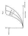
- mounting tolerances for bends and branches can affect the characteristics of air mass flow and static pressure. If no tolerance is used, the system has the in FIG. 2 If the maximum error in a first direction is taken as the basis, the system has the characteristic 104 and if the maximum error is based on a second, opposite direction, the system has the characteristic 105. If a point or a characteristic moves inside of the limited by the characteristics 104 and 105 area, leakage can not be detected.
- FIG. 3 shows the characteristic 103, in which no tolerance is used.
- the characteristic curve 104 shows the case in which a maximum tolerance in a first direction is used
- the characteristic curve 105 shows the case in which a maximum tolerance in a second, opposite direction is used. If a point of the characteristic curve 103 moves between the area bounded by the characteristic lines 104 and 105, leakage is not detectable.
- the characteristic curve 102 shows a line with a leakage. Since the characteristic 102 is outside the range bounded by the characteristics 104 and 105, this leakage can be detected. The leakage must therefore have a relatively large extent so that it can be detected. In the in the FIG.
- the working point 106 of the system is on the characteristic 104, since all components of the system have the maximum tolerance in the first direction.
- the ratio of mass air flow to static pressure shifts to point 107. It can be seen that the static pressure must change by a large amount so that the leakage can be detected. Under certain circumstances, this leads to the fact that a small leakage can not be recognized, but which nevertheless can lead to the structural problems mentioned at the beginning in the case of blades made of a composite material but also in the case of a wing of the prior art made of metal.
- the case is shown in which all components of the system have a maximum tolerance in the second, opposite direction.
- the operating point 108 of the system is in the normal operation on the characteristic 105.
- the operating point 107 is on the characteristic curve 102. Even with a small change in the static pressure from the value DP1 to the value DP2, the system detects a leak. Thus, it is possible that a small pressure change is interpreted as leakage.
- FIG. 5 shows the characteristic 103, the ratio of air mass flow to static pressure, if no tolerances are used.
- the characteristic 104 represents the case where all components of the system have a tolerance in the first direction
- the characteristic 105 represents the case where all components of the system have a tolerance in the second, opposite direction.
- the operating point 109 of the system lies on the characteristic 104. All components of the system therefore have a tolerance in the first direction.
- the operating point 107 on the characteristic curve 102 This is within the undetectable range between the characteristics 104 and 105, as previously described.
- the prior art system can not detect a relatively large change in static pressure. Therefore, there may be problems with the structural integrity of the wing, as hot air may enter the wing without being recognized by a prior art system.
- an aircraft line monitoring system having an airline-mountable conduit that directs gas from a source to a deployment site.
- a flow detection device is arranged, which detects a gas mass flow in the line.
- a pressure detection device detects a static pressure in the line.
- a control device is designed to detect at least one learning operation-actual gas mass flow in a learning operation and to store the learning operation-actual gas mass flow as desired gas mass flow for normal operation.
- the controller is further configured to detect a learning operation actual pressure and to store it as a target pressure for normal operation.
- a leak in the line to be monitored is excluded, so that the values of the learning mode actual gas mass flow and the learning mode actual pressure detected in the learning mode correspond to gas mass flow and pressure values in a line without a leak.
- the controller compares a normal operation-actual gas mass flow with the target gas mass flow and / or a normal operation-actual pressure with the set pressure.
- gas also includes a gas mixture, such as air, and any gaseous fluid.
- the location of use may be an air outlet on a wing or a nozzle in a passenger cabin.
- bends in the line, branches and other assembly tolerances affect the characteristics between air mass flow and static pressure.
- the sensitivity of the aircraft line monitoring system is not affected by these tolerances, since the influence of these tolerances is taken into account in the learning mode of the control device.
- the aircraft line monitoring system also has the advantage that static tolerances of the flow sensing device, the pressure sensing device, and the temperature sensor do not limit the sensitivity of the system.
- the aircraft line monitoring system described above is particularly suitable for applications in which only one operating point of air mass flow and static pressure is used in normal operation.
- the aircraft line monitoring system detects, in the learning mode, a plurality of learning operation actual gas mass flow values at different learning operation actual pressures, respectively.
- the controller allocates each learning operation actual gas mass flow to a learning operation actual pressure.
- Each learning operation actual gas mass flow is stored as a target gas mass flow and each learning operation actual pressure is stored as a target pressure for a normal operation.
- the control device also stores an association between the respective desired pressure and the respective desired volume flow.
- the control device receives a normal operation-actual gas mass flow value from the flow detection device and a normal operation-actual pressure value from the pressure detection device. It is compared to the normal operation-actual pressure associated target gas mass flow with the normal operation-actual gas mass flow.
- the control device If the normal operation actual gas mass flow deviates by more than a threshold value from the target gas mass flow, the control device outputs a signal indicating a deviation.
- the control device may alternatively or additionally receive a normal operation-actual gas mass flow from the flow detection device in normal operation and obtain a normal operation-actual pressure from the pressure detection device. The nominal pressure associated with the normal operation actual gas mass flow is compared with the normal operation actual pressure. If the normal operation actual pressure differs by more than a threshold value from the target pressure, the controller outputs a signal indicating a deviation. It is understood that the controller may output a signal indicative of a deviation and / or output a signal or value indicative of the magnitude of the deviation.
- this aircraft line monitoring system a plurality of points on the gas mass flow to static pressure characteristic line are received in the line.
- This system is suitable for an application in which the values of the gas mass flow and / or the static pressure in operation depending on Operating mode can be varied. Any number of points can be recorded on the characteristic curve. Further, the controller may interpolate between the recorded points. This interpolation can be done during the learning mode or during normal operation. Apart from numerical inaccuracies, the interpolation maintains the relationship between the set pressure and the set flow rate, depending on the interpolation method used.
- the flow sensing device may include a venturi nozzle and provide a difference between a pressure prevailing upstream of the venturi nozzle and a pressure prevailing downstream of the venturi nozzle as a measure of the gas flow rate.
- the flow rate detection device may also be a so-called hot wire anomometer.
- a hot-wire anomometer has a temperature-dependent electrical resistance, which is electrically heated.
- the electrical conductor is cooled as a function of the flow rate.
- the temperature of the electrical resistance can be determined by means of a resistance measurement, which makes it possible to deduce the flow velocity.
- a temperature sensor may be provided in the line or in the flow rate detection device.
- the gas volume flow corresponds to the quotient of the gas mass flow and the density of the gas or gas mixture.
- the density of the gas or gas mixture depends on the temperature.
- a gas mass flow value can be exchanged for a gas volume flow value.
- the flow detection device can detect a gas volume flow and the control device can process a gas volume flow value instead of a gas mass flow value. It is also conceivable that the flow rate detection device detects a gas volume flow and the control device calculates a gas mass flow value by means of a temperature value. The flow detection device can detect the gas volume flow and determine and output the gas mass flow by means of a detected temperature.
- An aircraft wing de-icing system comprises the aircraft line monitoring system described above.
- the location where the conduit of the aircraft line monitoring system directs the gas flowing through the conduit comprises at least one gas outlet in an aircraft wing.
- the aircraft wing may be an airfoil of a conventional aircraft or a wing moving in the form of a rotor blade of a helicopter relative to the aircraft.
- An aircraft air conditioning system comprises the aircraft line monitoring system described above.
- the location where the line of the aircraft line monitoring system directs the gas flowing through the line is, for example, at least one nozzle which supplies air to the cabin.
- the invention also relates to a method of monitoring a mass flow of gas in an aircraft-mounted conduit from a gas source to a deployment site having a learning operation and a normal operation.
- a learning operation actual gas mass flow is determined, a learning operation actual pressure determined, and the learning operation actual gas mass flow as the target gas mass flow and the learning operation actual pressure as the target pressure.
- a normal operation-actual gas mass flow is determined, a normal operation-actual pressure determined, the normal operation-actual gas mass flow with the desired mass flow and / or the normal operation-actual pressure compared with the target pressure and outputs a warning signal, if the normal operation-actual gas mass flow deviates from the desired gas mass flow by more than a threshold value and / or the normal operation-actual pressure deviates from the target pressure by more than a threshold value.
- the method detects a plurality of learning mode actual gas mass flow values at respectively different learning operation actual pressures.
- Each learning mode actual gas mass flow is assigned to the respective learning mode actual pressure.
- Each learning operation-actual gas mass flow is stored as a target gas mass flow, each learning operation-actual pressure is stored as a target pressure and also an association between the respective target pressure and the respective target gas mass flow is stored.
- the method performs the detection of the normal operation gas mass flow and the detection of the normal operation actual pressure. Subsequently, the nominal gas mass flow associated with the normal operation actual pressure with the normal operation actual gas mass flow compared and / or compared to the normal operation-actual gas mass flow associated desired pressure with the normal operation-actual pressure. A warning signal is output if the normal operation-actual gas mass flow deviates from the respective desired gas mass flow or the normal operation-actual pressure deviates from the respective desired pressure by more than a threshold value.
- the method may interpolate between at least two desired pressure values and / or at least two desired gas mass flow values.
- the method can be controlled at least partially by the control device described above.
- the controller may be implemented by a computer having a memory. It is understood that the control device can also be formed by a plurality of separate devices that implement one or more steps of the method described above.
- the controller may include a memory device, a comparator, an output device, an interpolator, and the like.
- a gas volume flow value can be detected and processed.
- the physical relationships described above can be used.
- the method may be used to detect an air supply disruption during defrost of an aircraft wing.
- the location where the conduit of the aircraft line monitoring system directs the gas flowing through the conduit then comprises at least one gas outlet in the aircraft wing.
- the method may be used to monitor the air supply when air conditioning the aircraft cabin. In this method, for example, at least one air outlet nozzle in the cabin forms the location where the line of the aircraft line monitoring system directs the gas flowing through the line.
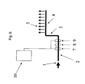
- FIG. 6 shows an air duct system comprising a first conduit 2, a second conduit 3 and a third conduit, which are arranged one behind the other.
- the airflow 1 may be hot engine bleed air.
- the third conduit 4 has openings 5 through which the air exits the conduit.
- the openings 5 may be transverse to the direction of the airflow and / or in the same direction as the airflow. It can also be provided only an opening.
- the openings 5 may be located, for example, in a wing of an aircraft to de-ice the wing.
- the air flow 1 is supplied by an air conditioner and the openings 5 are located in a cabin of an aircraft.
- the first line 2 there is a flow rate detection device 7, an optional temperature sensor 8 and a pressure detection device 9.
- the optional temperature sensor 8 is coupled to the flow rate detection device 7.
- the flow rate detection device 7 and the pressure detection device 9 are coupled to a control device 10. It is also possible that the optional temperature sensor 8 is not coupled to the flow rate detection device 7 but to the control device 10.
- the flow sensing device 7 may include a venturi and provide a pressure differential upstream and downstream of the venturi as a measure of the gas flow rate.
- the flow rate detection device 7 may also be a so-called hot wire anomometer.
- a hot-wire anomometer has a temperature-dependent electrical resistance, which is electrically heated.
- the electrical conductor is cooled as a function of the flow rate.
- the temperature of the electrical resistance can be determined by means of a resistance measurement, which makes it possible to deduce the flow velocity.
- the air volume flow is the quotient of the air mass flow and the density of air.
- the density of air depends on the temperature.
- the air mass flow can be calculated from a detected air volume flow and a temperature.
- the flow rate detection device 7 and the temperature sensor 8 provide an actual value of the air mass flow.
- the pressure detector 9 provides an actual value of the static pressure in the first conduit.
- a learning operation actual gas mass flow and a learning operation actual pressure are detected.
- the controller 10 stores the learning operation actual air mass flow as the target air mass flow and the learning operation actual pressure as the target pressure.
- the normal operation-actual air mass flow and the normal operation-actual pressure is determined.
- the normal operation-actual air mass flow is compared with the desired air mass flow and / or the normal operation-actual pressure is compared with the target pressure by the control device.
- a warning signal is issued if the normal operation-actual air mass flow deviates from the desired air mass flow by more than a threshold value or the normal operation-actual pressure deviates from the target pressure by more than a threshold value.
- This procedure is suitable if the air line system is operated only at a desired pressure or nominal air mass flow. This may be the case with a de-icing system for a wing of an aircraft.
- a plurality of learning mode actual air mass flow values may also be determined at respectively different learning operation actual pressures.
- Each learning mode actual air mass flow is assigned to the respective learning mode actual pressure.
- the controller 10 stores each learning operation actual air mass flow value as the target air mass flow value, each learning operation actual pressure value as the target pressure value, and an association between the respective target pressure and the respective target air mass flow.
- the assignment can be achieved by pairwise saving, by storing in a table, by pointers and the like.
- the in FIG. 7 generated by the reference numeral 12 system characteristic of the static pressure in dependence of the air mass flow.
- the system characteristic 12 takes into account influences of line bends, line branches, a cable diameter and their dispersion.
- This characteristic curve also records the static measurement errors of the measured values of receiving and processing components in the airline system.
- a region 16 in which a leak can not be detected comprises only the dynamic tolerances of the components receiving and processing measured values, for example their aging and their temperature dispersion. Depending on the design, it can also include the aging and temperature dispersion of the line components. Thus, the region 16 in which leakage can not be detected is much smaller than in a prior art system.
- interpolation can be made between the desired air mass flow values and / or desired pressure values.
- the interpolation may be performed during the learning operation or the normal operation.
- various techniques are known, for example a polynomial interpolation or a spillover interpolation and the like, so that these interpolation methods require no further explanation.
- the learning operation is required only once after the assembly of the aircraft or after replacement of piping components of the air duct system, the flow rate detecting device, the temperature sensor or the pressure detecting device.
- the learning operation can also be repeated during maintenance in order to take into account the aging phenomena of the measurement-receiving and processing components and to minimize the region 16 in which leakage can not be detected.
- the normal operation-actual air mass flow and the normal operation-actual pressure are detected.
- the nominal air mass flow associated with the normal operation actual pressure is compared with the normal operation actual air mass flow. Additionally or alternatively, the nominal pressure associated with the normal operation-actual air mass flow can be compared with the normal operation-actual pressure.
- a warning signal is output if the normal operation-actual air mass flow from the respective desired air mass flow or the normal operation-actual pressure deviates from the respective desired pressure by more than a threshold value.
- the control device assigns the static air pressure LM1 to the air mass flow LM1.
- the air mass flow LM1 is stored as the desired air mass flow and the static pressure DP1 is stored as the desired pressure. This point of the characteristic is identified by the reference numeral 18.
- the air mass flow LM1 and the static pressure DP2 are detected. This point is identified by the reference numeral 20.
- the air mass flow LM1 is associated with the desired pressure DP1.
- the normal operation actual pressure is DP2.
- the difference between DP1 and DP2 is greater than a predetermined threshold.
- the controller 10 indicates that there is leakage.
- the present invention has the advantage that in addition to a leakage and a partial or complete blockage of a pipe and / or nozzle or a change in the air source can be detected, since this changes the characteristic of the static pressure on the air mass flow. Furthermore, the present invention can take into account static measurement errors of the sensors used. The present invention may also consider influences by bends in the ducts, branch lines and the like. The area 16, in which a fault in the air duct system can not be detected, is considerably smaller in the aircraft line monitoring system according to the invention than in the prior art. The present invention provides a safer aircraft because de-icing of the wing can be better monitored.
- the entry of hot air into the wing and the concomitant danger of structural instability, particularly when using composite materials in the wing, can be detected more reliably than in the prior art. Further, a more comfortable Aircraft created because the function of the air conditioning can be better monitored.
Landscapes
- Engineering & Computer Science (AREA)
- Aviation & Aerospace Engineering (AREA)
- Physics & Mathematics (AREA)
- General Physics & Mathematics (AREA)
- Health & Medical Sciences (AREA)
- General Health & Medical Sciences (AREA)
- Pulmonology (AREA)
- Measuring Volume Flow (AREA)
- Examining Or Testing Airtightness (AREA)
- Pipeline Systems (AREA)
Claims (13)
- Système de surveillance d'un conduit d'aéronef comprenant- un conduit (2, 3, 4) qui amène du gaz d'une source (1) jusqu'à un lieu d'utilisation (5),- un dispositif de relevé de débit (7) pour relever un débit massique de gaz dans le conduit (2),- un dispositif de relevé de pression (9) pour relever une pression statique dans le conduit (2), et- un dispositif de commande (10) conçu pour- au cours d'un fonctionnement en mode d'apprentissage, relever au moins une valeur instantanée de débit massique de gaz de fonctionnement en mode d'apprentissage et mémoriser la valeur instantanée de débit massique de gaz de fonctionnement en mode d'apprentissage en tant que débit massique de gaz de consigne pour un fonctionnement en mode normal, et pour relever une valeur instantanée de pression de fonctionnement en mode d'apprentissage et mémoriser la valeur instantanée de pression de fonctionnement en mode d'apprentissage en tant que pression de consigne pour le fonctionnement en mode normal, et- lors du fonctionnement en mode normal, comparer un débit massique de gaz instantané de fonctionnement en mode normal avec le débit massique de gaz de consigne, et/ou une pression instantanée de fonctionnement en mode normal avec la pression de consigne, et, dans le cas où le débit massique de gaz instantané de fonctionnement en mode normal s'écarte de plus d'une valeur de seuil du débit massique de gaz de consigne, et/ou dans le cas où la pression instantanée de fonctionnement en mode normal s'écarte de plus d'une valeur de seuil de la pression de consigne, délivrer un signal qui indique un écart,caractérisé en ce que le dispositif de commande (10) est par ailleurs conçu pour relever, lors du fonctionnement en mode d'apprentissage, une pluralité de valeurs instantanées de débit massique de gaz de fonctionnement en mode d'apprentissage pour des pressions instantanées de fonctionnement en mode d'apprentissage respectivement différentes, associer à chaque valeur instantanée de débit massique de gaz de fonctionnement en mode d'apprentissage une valeur instantanée de pression de fonctionnement en mode d'apprentissage correspondante, et mémoriser chaque valeur instantanée de débit massique de gaz de fonctionnement en mode d'apprentissage en tant que débit massique de gaz de consigne pour un fonctionnement en mode normal, chaque valeur instantanée de pression de fonctionnement en mode d'apprentissage en tant que pression de consigne pour un fonctionnement en mode normal, et une association entre la pression de consigne respective et le débit massique de gaz de consigne respectif.
- Système de surveillance d'un conduit d'aéronef selon la revendication 1,
caractérisé en ce que le dispositif de commande (10) est par ailleurs conçu pour- lors du fonctionnement en mode normal, obtenir un débit massique de gaz instantané de fonctionnement en mode normal à partir du dispositif de relevé de débit (7), et une pression instantanée de fonctionnement en mode normal à partir du dispositif de relevé de pression (9), comparer le débit massique de gaz de consigne associé à la pression instantanée de fonctionnement en mode normal avec le débit massique de gaz instantané de fonctionnement en mode normal, et, dans le cas où le débit massique de gaz instantané de fonctionnement en mode normal s'écarte de plus d'une valeur de seuil du débit massique de gaz de consigne, délivrer le signal qui indique un écart, et/ou- lors du fonctionnement en mode normal, obtenir un débit massique de gaz instantané de fonctionnement en mode normal à partir du dispositif de relevé de débit (7), et une pression instantanée de fonctionnement en mode normal à partir du dispositif de relevé de pression (9), comparer la pression de consigne associée au débit massique de gaz instantané de fonctionnement en mode normal avec la pression instantanée de fonctionnement en mode normal, et, dans le cas où la pression instantanée de fonctionnement en mode normal s'écarte de plus d'une valeur de seuil de la pression de consigne, délivrer le signal qui indique un écart. - Système de surveillance d'un conduit d'aéronef selon la revendication 1 ou la revendication 2,
caractérisé en ce que le dispositif de commande (10) est conçu pour interpoler entre au moins deux valeurs de pression de consigne et/ou au moins deux valeurs de débit massique de gaz de consigne. - Système de surveillance d'un conduit d'aéronef selon l'une des revendications 1 à 3,
caractérisé en ce que le dispositif de relevé de débit (7) comprend un tube de Venturi, et fournit une différence entre une pression prédominante en amont du tube de Venturi et une pression prédominante en aval du tube de Venturi, et la température du gaz fournissant une mesure pour le débit massique de gaz. - Système de surveillance d'un conduit d'aéronef selon l'une des revendications 1 à 4,
caractérisé en ce que le dispositif de relevé de débit (7) relève un débit-volume de gaz, et en ce que le dispositif de commande (10) est conçu pour traiter, à la place d'une valeur de débit massique de gaz, une valeur de débit-volume de gaz. - Système de dégivrage d'aile d'aéronef comprenant un système de surveillance de conduit d'aéronef selon l'une des revendications 1 à 5, dans lequel le lieu d'utilisation, vers lequel le conduit (2, 3, 4) du système de surveillance de conduit d'aéronef amène le gaz qui s'écoule à travers le conduit (2, 3, 4), comprend au moins une sortie de gaz (5) dans une aile d'aéronef.
- Installation de climatisation d'aéronef comprenant un système de surveillance de conduit d'aéronef selon l'une des revendications 1 à 5.
- Procédé de surveillance d'un débit massique de gaz dans un conduit (2, 3, 4) pouvant être implanté dans un aéronef, qui dirige du gaz d'une source (1) vers un lieu d'utilisation (5), procédé selon lequel sont exécutés, au cours d'un fonctionnement en mode d'apprentissage, les étapes de procédé suivantes :- détermination d'une valeur instantanée de débit massique de gaz de fonctionnement en mode d'apprentissage du gaz s'écoulant dans le conduit (2, 3, 4),- détermination d'une valeur instantanée de pression de fonctionnement en mode d'apprentissage de la pression statique dans le conduit (2, 3, 4), et- mémorisation de la valeur instantanée de débit massique de gaz de fonctionnement en mode d'apprentissage en tant que débit massique de gaz de consigne, et de la valeur instantanée de pression de fonctionnement en mode d'apprentissage en tant que pression de consigne, etselon lequel sont exécutés, au cours du fonctionnement en mode normal, les étapes de procédé suivantes :- détermination d'un débit massique de gaz instantané de fonctionnement en mode normal dans le conduit (2, 3, 4),- détermination d'une valeur instantanée de pression de fonctionnement en mode normal de la pression statique dans le conduit (2, 3, 4),- comparaison du débit massique de gaz instantané de fonctionnement en mode normal avec le débit massique de gaz de consigne, et/ou comparaison de la valeur instantanée de pression de fonctionnement en mode normal avec la pression de consigne, et- délivrance d'un signal d'avertissement, dans le cas où le débit massique de gaz instantané de fonctionnement en mode normal s'écarte de plus d'une valeur de seuil du débit massique de gaz de consigne, et/ou dans le cas où la pression instantanée de fonctionnement en mode normal s'écarte de plus d'une valeur de seuil de la pression de consigne,caractérisé en ce que lors du fonctionnement en mode d'apprentissage sont exécutés, par ailleurs, les étapes suivantes :- détermination d'une pluralité de valeurs instantanées de débit massique de gaz de fonctionnement en mode d'apprentissage pour des pressions instantanées de fonctionnement en mode d'apprentissage respectivement différentes,- association de chaque valeur instantanée de débit massique de gaz de fonctionnement en mode d'apprentissage à la valeur instantanée de pression de fonctionnement en mode d'apprentissage respective, et- mémorisation de chaque valeur instantanée de débit massique de gaz de fonctionnement en mode d'apprentissage en tant que débit massique de gaz de consigne pour un fonctionnement en mode normal, de chaque valeur instantanée de pression de fonctionnement en mode d'apprentissage en tant que pression de consigne pour un fonctionnement en mode normal, et d'une association entre la pression de consigne respective et le débit massique de gaz de consigne respectif.
- Procédé selon la revendication 8,
caractérisé en ce que lors du fonctionnement en mode normal, sont par ailleurs exécutés les étapes suivantes :- relevé du débit massique de gaz instantané de fonctionnement en mode normal,- relevé de la pression instantanée de fonctionnement en mode normal,- comparaison du débit massique de gaz de consigne associé à la pression instantanée de fonctionnement en mode normal avec le débit massique de gaz instantané de fonctionnement en mode normal, et/ou comparaison de la pression de consigne associée au débit massique de gaz instantané de fonctionnement en mode normal avec la pression instantanée de fonctionnement en mode normal, et- délivrance d'un signal d'avertissement, dans le cas où le débit massique de gaz instantané de fonctionnement en mode normal s'écarte de plus d'une valeur de seuil du débit massique de gaz de consigne respectif, et/ou la pression instantanée de fonctionnement en mode normal s'écarte de plus d'une valeur de seuil de la pression de consigne respective. - Procédé selon la revendication 8 ou la revendication 9,
caractérisé par l'étape de l'interpolation entre au moins deux valeurs de pression de consigne et/ou au moins deux valeurs de débit massique de gaz de consigne. - Procédé selon l'une des revendications 8 à 10,
caractérisé en ce qu'une valeur de débit-volume de gaz est relevée et traitée à la place d'une valeur de débit massique de gaz. - Procédé de surveillance du dégivrage d'une aile d'aéronef comprenant les étapes du procédé selon l'une des revendications 8 à 11, dans lequel le lieu d'utilisation, vers lequel le conduit (2, 3, 4) du système de surveillance de conduit d'aéronef amène le gaz qui s'écoule à travers le conduit (2, 3, 4), comprend au moins une buse de sortie de gaz dans l'aile d'aéronef.
- Procédé de surveillance de la climatisation d'une cabine d'aéronef comprenant les étapes du procédé selon l'une des revendications 8 à 11.
Applications Claiming Priority (3)
| Application Number | Priority Date | Filing Date | Title |
|---|---|---|---|
| US7418508P | 2008-06-20 | 2008-06-20 | |
| DE102008029469A DE102008029469B3 (de) | 2008-06-20 | 2008-06-20 | Luftfahrzeugleitungsüberwachungssystem und -verfahren, insbesondere für ein Luftfahrzeugflügelenteisungssystem und eine Luftfahrzeugklimaanlage |
| PCT/EP2009/004368 WO2009153033A2 (fr) | 2008-06-20 | 2009-06-17 | Système et procédé de surveillance de conduit dans un aéronef |
Publications (2)
| Publication Number | Publication Date |
|---|---|
| EP2296969A2 EP2296969A2 (fr) | 2011-03-23 |
| EP2296969B1 true EP2296969B1 (fr) | 2013-03-13 |
Family
ID=41112132
Family Applications (1)
| Application Number | Title | Priority Date | Filing Date |
|---|---|---|---|
| EP09765613A Active EP2296969B1 (fr) | 2008-06-20 | 2009-06-17 | Système et procédé de surveillance de conduit dans un aéronef |
Country Status (9)
| Country | Link |
|---|---|
| US (1) | US8511179B2 (fr) |
| EP (1) | EP2296969B1 (fr) |
| JP (1) | JP5373894B2 (fr) |
| CN (1) | CN102066194B (fr) |
| BR (1) | BRPI0915380A2 (fr) |
| CA (1) | CA2728369A1 (fr) |
| DE (1) | DE102008029469B3 (fr) |
| RU (1) | RU2011100468A (fr) |
| WO (1) | WO2009153033A2 (fr) |
Families Citing this family (24)
| Publication number | Priority date | Publication date | Assignee | Title |
|---|---|---|---|---|
| DE102008029469B3 (de) * | 2008-06-20 | 2009-10-29 | Airbus Deutschland Gmbh | Luftfahrzeugleitungsüberwachungssystem und -verfahren, insbesondere für ein Luftfahrzeugflügelenteisungssystem und eine Luftfahrzeugklimaanlage |
| DE102008058451B4 (de) * | 2008-11-21 | 2010-11-18 | Airbus Deutschland Gmbh | Verfahren und System zur Notbelüftung einer Flugzeugkabine im Fall eines Lecks im Bereich eines Luftmischers |
| FR2999533B1 (fr) * | 2012-12-18 | 2015-06-26 | Airbus Operations Sas | Procede et dispositif de degivrage a air chaud des bords d'attaque d'un aeronef a reaction |
| JP6105156B2 (ja) * | 2013-04-30 | 2017-03-29 | マイクロ モーション インコーポレイテッド | 質量流量メーターおよび密度メーターを備えた体積流量センサーシステム |
| GB2516475A (en) * | 2013-07-24 | 2015-01-28 | Ikm Production Technology As | Measurement device |
| US9494050B2 (en) * | 2013-09-20 | 2016-11-15 | The Boeing Company | Concentric nozzles for enhanced mixing of fluids |
| WO2016065626A1 (fr) * | 2014-10-31 | 2016-05-06 | 深圳市大疆创新科技有限公司 | Procédé et appareil de traitement de fuite de gaz, et véhicule aérien |
| US10139795B2 (en) * | 2015-10-19 | 2018-11-27 | The Boeing Company | System and method for environmental control system diagnosis and prognosis |
| DE102016201924A1 (de) * | 2016-02-09 | 2017-08-10 | Lufthansa Technik Aktiengesellschaft | Flugzeug und Warneinrichtung für ein "Engine Oil Smell" in einer Flugzeugkabine eines Flugzeuges |
| US10457552B2 (en) | 2017-01-27 | 2019-10-29 | Hamilton Sundstrand Corporation | Flow sensing ozone converter |
| US10578498B2 (en) * | 2017-06-22 | 2020-03-03 | Unison Industries, Llc | Air temperature sensor |
| CN108357683B (zh) * | 2017-12-29 | 2021-03-23 | 西北工业大学 | 一种基于空速管的小型无人机结冰探测方法 |
| CN108224097B (zh) * | 2018-01-30 | 2022-08-02 | 北京建筑大学 | 一种天然气管道泄漏报警系统和检测方法 |
| FR3094345B1 (fr) * | 2019-03-27 | 2021-03-05 | Thales Sa | Équipement aéronautique pour un aéronef |
| FR3098592B1 (fr) * | 2019-07-12 | 2021-09-17 | Airbus Operations Sas | Surveillance d’un circuit pneumatique d’antigivrage pour une voilure d’aéronef |
| CN110879122A (zh) * | 2019-12-13 | 2020-03-13 | 西安飞机工业(集团)有限责任公司 | 一种飞机机翼油箱密封性检测装置及检测方法 |
| US11530710B2 (en) * | 2020-01-28 | 2022-12-20 | Pratt & Whitney Canada Corp. | Aircraft pneumatic system |
| US11567476B2 (en) * | 2020-06-23 | 2023-01-31 | Horiba Stec, Co., Ltd. | Computing system with discriminative classifier for determining similarity of a monitored gas delivery process |
| CN112013286B (zh) * | 2020-08-26 | 2022-03-11 | 辽宁石油化工大学 | 管道泄漏点的定位方法及装置、存储介质、终端 |
| CN112103918B (zh) * | 2020-08-31 | 2022-03-29 | 山东钢铁集团日照有限公司 | 一种数字式变压器瓦斯继电保护方法 |
| CN113944891B (zh) * | 2021-11-05 | 2023-04-18 | 中国安全生产科学研究院 | 一种化工装置设施泄漏检测修正方法 |
| CN114420325A (zh) * | 2022-01-30 | 2022-04-29 | 上海核工程研究设计院有限公司 | 一种基于流量测量的主蒸汽管道泄漏监测系统 |
| CN117450438B (zh) * | 2023-12-07 | 2026-04-14 | 中国航空工业集团公司成都飞机设计研究所 | 一种飞机舵面操纵系统管路泄漏检测和处置的方法及装置 |
| CN120397283B (zh) * | 2025-04-11 | 2026-03-03 | 中国东方航空设备集成有限公司 | 一种飞机除霜车用吹气气压调控方法及系统 |
Family Cites Families (18)
| Publication number | Priority date | Publication date | Assignee | Title |
|---|---|---|---|---|
| GB1279476A (en) * | 1968-12-10 | 1972-06-28 | Tokyo Shibaura Electric Co | Fracture detecting means for a fluid pipe line |
| GB1301851A (fr) * | 1969-04-03 | 1973-01-04 | ||
| US4482114A (en) * | 1981-01-26 | 1984-11-13 | The Boeing Company | Integrated thermal anti-icing and environmental control system |
| JPS5866036A (ja) * | 1981-10-15 | 1983-04-20 | Toshiba Corp | 原子炉冷却材浄化系の漏洩検出装置 |
| US4655607A (en) * | 1983-12-19 | 1987-04-07 | Santa Barbara Research Center | High speed hot air leak sensor |
| JPS61160395A (ja) * | 1985-01-09 | 1986-07-21 | 財団法人日本航空機開発協会 | 航空機の防氷装置 |
| DE3810998A1 (de) * | 1988-03-31 | 1989-10-19 | Eckardt Ag | Verfahren zur erfassung von aenderungen einer vorgegebenen geometrie eines durchstroemten rohrleitungsnetzes |
| US5272646A (en) * | 1991-04-11 | 1993-12-21 | Farmer Edward J | Method for locating leaks in a fluid pipeline and apparatus therefore |
| US5295391A (en) * | 1992-02-11 | 1994-03-22 | Nde Environmental Corporation | Method and apparatus for detecting leaks in the ullage of a liquid storage tank |
| US5601071A (en) * | 1995-01-26 | 1997-02-11 | Tridelta Industries, Inc. | Flow control system |
| JPH08219934A (ja) * | 1995-02-09 | 1996-08-30 | Tokyo Gas Co Ltd | ガス導管からのガスの漏洩検知方法 |
| GB9805422D0 (en) * | 1998-03-13 | 1998-05-06 | Standard Aero Limited | Gas flow area measurement |
| CN1101914C (zh) | 2001-05-31 | 2003-02-19 | 山东新大通石油环保科技股份有限公司 | 输送管线泄漏监控定位方法及其适用的系统 |
| KR20100105906A (ko) * | 2002-07-19 | 2010-09-30 | 엔테그리스, 아이엔씨. | 유체유동측정 및 비례유체유동 제어장치 |
| GB0318339D0 (en) | 2003-08-05 | 2003-09-10 | Oxford Biosignals Ltd | Installation condition monitoring system |
| JP4086057B2 (ja) * | 2004-06-21 | 2008-05-14 | 日立金属株式会社 | 質量流量制御装置及びこの検定方法 |
| US7778735B2 (en) * | 2006-11-17 | 2010-08-17 | The Boeing Company | Environmental control system, method, and computer program product for controlling the interior environment of a pressurized compartment |
| DE102008029469B3 (de) * | 2008-06-20 | 2009-10-29 | Airbus Deutschland Gmbh | Luftfahrzeugleitungsüberwachungssystem und -verfahren, insbesondere für ein Luftfahrzeugflügelenteisungssystem und eine Luftfahrzeugklimaanlage |
-
2008
- 2008-06-20 DE DE102008029469A patent/DE102008029469B3/de not_active Expired - Fee Related
-
2009
- 2009-06-17 JP JP2011513945A patent/JP5373894B2/ja not_active Expired - Fee Related
- 2009-06-17 CA CA2728369A patent/CA2728369A1/fr not_active Abandoned
- 2009-06-17 BR BRPI0915380A patent/BRPI0915380A2/pt not_active Application Discontinuation
- 2009-06-17 RU RU2011100468/11A patent/RU2011100468A/ru unknown
- 2009-06-17 US US12/999,752 patent/US8511179B2/en active Active
- 2009-06-17 WO PCT/EP2009/004368 patent/WO2009153033A2/fr not_active Ceased
- 2009-06-17 CN CN2009801231975A patent/CN102066194B/zh active Active
- 2009-06-17 EP EP09765613A patent/EP2296969B1/fr active Active
Also Published As
| Publication number | Publication date |
|---|---|
| CA2728369A1 (fr) | 2009-12-23 |
| RU2011100468A (ru) | 2012-07-27 |
| DE102008029469B3 (de) | 2009-10-29 |
| WO2009153033A4 (fr) | 2010-06-24 |
| CN102066194A (zh) | 2011-05-18 |
| EP2296969A2 (fr) | 2011-03-23 |
| JP5373894B2 (ja) | 2013-12-18 |
| JP2011524300A (ja) | 2011-09-01 |
| WO2009153033A2 (fr) | 2009-12-23 |
| BRPI0915380A2 (pt) | 2015-11-03 |
| CN102066194B (zh) | 2013-09-18 |
| WO2009153033A3 (fr) | 2010-04-29 |
| US8511179B2 (en) | 2013-08-20 |
| US20110247432A1 (en) | 2011-10-13 |
Similar Documents
| Publication | Publication Date | Title |
|---|---|---|
| EP2296969B1 (fr) | Système et procédé de surveillance de conduit dans un aéronef | |
| DE69405159T2 (de) | Regelung einer Gasturbine auf der Basis von Einlassdruckdistorsion | |
| EP2407946B1 (fr) | Détection d'encrassements et de ruptures dans un détecteur de fumées par aspiration (ASD) | |
| DE60018728T2 (de) | Feste multifunktionssonde für luftfahrzeug | |
| EP2475920B1 (fr) | Système de diagnostic pour une soupape | |
| EP1116655B1 (fr) | Système de contrôle d'un courant de masse d'air avec correction pour l'altitude barométrique pour un avion de transport | |
| EP3397860B1 (fr) | Procédé permettant de déterminer une valeur pour une quantité d'accumulation de givre sur au moins une pale de rotor d'une éolienne et son utilisation | |
| EP3510372A1 (fr) | Dispositif et procédé de mesure de poussée sur l'aile de propulseurs d'aéronefs | |
| WO2020099389A1 (fr) | Procédé d'évaluation du rendement énergétique d'aéronefs | |
| DE112015004729T5 (de) | Mehrfachanwendungs-Öffnungs-Kondensatableitvorrichtung | |
| DE69401149T2 (de) | Schutz gegen die Löschung und/oder Pumpen einer Gasturbine bei Eindringen von Wasser | |
| DE102011116975B3 (de) | Verfahren und Vorrichtung zum Bestimmen der Schubkraft eines Triebwerks an einem Fahrzeug | |
| DE3340516A1 (de) | Verfahren und system zur korrektur der netto-schubmessungen in einer flugtriebwerks-pruefzelle | |
| DE2917255A1 (de) | Rissanzeigeeinrichtung zur ueberwachung der isolierung von fluessiggastanks | |
| DE60311939T2 (de) | Eine Methode zum Anzeigen der Position eines Ventilmitglieds | |
| WO2009071602A2 (fr) | Réseaux de capteurs et dispositif de surveillance d'état pour un aéronef, ainsi que procédé de surveillance d'état | |
| DE102006023498A1 (de) | Schaltanordnung zum Schutz eines Zapfluftzufuhrsystems eines Flugzeuges vor Überhitzung und Zapfluftzufuhrsystem mit einer solchen Schaltanordnung | |
| DE69203063T2 (de) | Schutzsystem gegen die Löschung einer Turbomaschine bei Eindrigen von Wasser oder Hagel. | |
| EP0696787A1 (fr) | Dispositif et méthode de détection d'incendie à compensation de la pression d'air | |
| DE102010017434A1 (de) | Einrichtung und Verfahren zum Testen eines Verdichters | |
| EP3612279B1 (fr) | Installation d'extinction d'incendie, système d'extinction d'incendie comportant cette dernière, ainsi que procédé pour la détermination de la propagation d'un feu | |
| EP2930492B1 (fr) | Dispositif de mesure de vapeur d'eau | |
| DE102011008219B4 (de) | Verfahren und Vorrichtung zur Bestimmung eines einen Stauluftkanal durchströmenden Luftmassenstroms | |
| WO2009083558A2 (fr) | Système et procédé pour mesurer et empêcher les phénomènes de givrage dans une conduite | |
| DE102020134027A1 (de) | Kälteanlage mit Wärmepumpenfunktion und Steuereinheit zur Vereisungsbestimmung, Betriebsverfahren für und Kraftfahrzeug mit einer solchen Kälteanlage |
Legal Events
| Date | Code | Title | Description |
|---|---|---|---|
| PUAI | Public reference made under article 153(3) epc to a published international application that has entered the european phase |
Free format text: ORIGINAL CODE: 0009012 |
|
| 17P | Request for examination filed |
Effective date: 20101215 |
|
| AK | Designated contracting states |
Kind code of ref document: A2 Designated state(s): AT BE BG CH CY CZ DE DK EE ES FI FR GB GR HR HU IE IS IT LI LT LU LV MC MK MT NL NO PL PT RO SE SI SK TR |
|
| AX | Request for extension of the european patent |
Extension state: AL BA RS |
|
| DAX | Request for extension of the european patent (deleted) | ||
| REG | Reference to a national code |
Ref country code: DE Ref legal event code: R079 Ref document number: 502009006488 Country of ref document: DE Free format text: PREVIOUS MAIN CLASS: B64D0013000000 Ipc: G01M0003280000 |
|
| RIC1 | Information provided on ipc code assigned before grant |
Ipc: B64D 13/00 20060101ALI20120730BHEP Ipc: B64D 15/02 20060101ALI20120730BHEP Ipc: G01M 3/28 20060101AFI20120730BHEP |
|
| GRAP | Despatch of communication of intention to grant a patent |
Free format text: ORIGINAL CODE: EPIDOSNIGR1 |
|
| GRAS | Grant fee paid |
Free format text: ORIGINAL CODE: EPIDOSNIGR3 |
|
| GRAA | (expected) grant |
Free format text: ORIGINAL CODE: 0009210 |
|
| AK | Designated contracting states |
Kind code of ref document: B1 Designated state(s): AT BE BG CH CY CZ DE DK EE ES FI FR GB GR HR HU IE IS IT LI LT LU LV MC MK MT NL NO PL PT RO SE SI SK TR |
|
| REG | Reference to a national code |
Ref country code: GB Ref legal event code: FG4D Free format text: NOT ENGLISH |
|
| REG | Reference to a national code |
Ref country code: CH Ref legal event code: EP Ref country code: AT Ref legal event code: REF Ref document number: 601078 Country of ref document: AT Kind code of ref document: T Effective date: 20130315 |
|
| REG | Reference to a national code |
Ref country code: IE Ref legal event code: FG4D Free format text: LANGUAGE OF EP DOCUMENT: GERMAN |
|
| REG | Reference to a national code |
Ref country code: DE Ref legal event code: R096 Ref document number: 502009006488 Country of ref document: DE Effective date: 20130508 |
|
| PG25 | Lapsed in a contracting state [announced via postgrant information from national office to epo] |
Ref country code: SE Free format text: LAPSE BECAUSE OF FAILURE TO SUBMIT A TRANSLATION OF THE DESCRIPTION OR TO PAY THE FEE WITHIN THE PRESCRIBED TIME-LIMIT Effective date: 20130313 Ref country code: ES Free format text: LAPSE BECAUSE OF FAILURE TO SUBMIT A TRANSLATION OF THE DESCRIPTION OR TO PAY THE FEE WITHIN THE PRESCRIBED TIME-LIMIT Effective date: 20130624 Ref country code: BG Free format text: LAPSE BECAUSE OF FAILURE TO SUBMIT A TRANSLATION OF THE DESCRIPTION OR TO PAY THE FEE WITHIN THE PRESCRIBED TIME-LIMIT Effective date: 20130613 Ref country code: NO Free format text: LAPSE BECAUSE OF FAILURE TO SUBMIT A TRANSLATION OF THE DESCRIPTION OR TO PAY THE FEE WITHIN THE PRESCRIBED TIME-LIMIT Effective date: 20130613 Ref country code: LT Free format text: LAPSE BECAUSE OF FAILURE TO SUBMIT A TRANSLATION OF THE DESCRIPTION OR TO PAY THE FEE WITHIN THE PRESCRIBED TIME-LIMIT Effective date: 20130313 |
|
| REG | Reference to a national code |
Ref country code: NL Ref legal event code: VDEP Effective date: 20130313 |
|
| REG | Reference to a national code |
Ref country code: LT Ref legal event code: MG4D |
|
| PG25 | Lapsed in a contracting state [announced via postgrant information from national office to epo] |
Ref country code: SI Free format text: LAPSE BECAUSE OF FAILURE TO SUBMIT A TRANSLATION OF THE DESCRIPTION OR TO PAY THE FEE WITHIN THE PRESCRIBED TIME-LIMIT Effective date: 20130313 Ref country code: FI Free format text: LAPSE BECAUSE OF FAILURE TO SUBMIT A TRANSLATION OF THE DESCRIPTION OR TO PAY THE FEE WITHIN THE PRESCRIBED TIME-LIMIT Effective date: 20130313 Ref country code: GR Free format text: LAPSE BECAUSE OF FAILURE TO SUBMIT A TRANSLATION OF THE DESCRIPTION OR TO PAY THE FEE WITHIN THE PRESCRIBED TIME-LIMIT Effective date: 20130614 Ref country code: LV Free format text: LAPSE BECAUSE OF FAILURE TO SUBMIT A TRANSLATION OF THE DESCRIPTION OR TO PAY THE FEE WITHIN THE PRESCRIBED TIME-LIMIT Effective date: 20130313 |
|
| PG25 | Lapsed in a contracting state [announced via postgrant information from national office to epo] |
Ref country code: HR Free format text: LAPSE BECAUSE OF FAILURE TO SUBMIT A TRANSLATION OF THE DESCRIPTION OR TO PAY THE FEE WITHIN THE PRESCRIBED TIME-LIMIT Effective date: 20130313 |
|
| PG25 | Lapsed in a contracting state [announced via postgrant information from national office to epo] |
Ref country code: CZ Free format text: LAPSE BECAUSE OF FAILURE TO SUBMIT A TRANSLATION OF THE DESCRIPTION OR TO PAY THE FEE WITHIN THE PRESCRIBED TIME-LIMIT Effective date: 20130313 Ref country code: EE Free format text: LAPSE BECAUSE OF FAILURE TO SUBMIT A TRANSLATION OF THE DESCRIPTION OR TO PAY THE FEE WITHIN THE PRESCRIBED TIME-LIMIT Effective date: 20130313 Ref country code: SK Free format text: LAPSE BECAUSE OF FAILURE TO SUBMIT A TRANSLATION OF THE DESCRIPTION OR TO PAY THE FEE WITHIN THE PRESCRIBED TIME-LIMIT Effective date: 20130313 Ref country code: RO Free format text: LAPSE BECAUSE OF FAILURE TO SUBMIT A TRANSLATION OF THE DESCRIPTION OR TO PAY THE FEE WITHIN THE PRESCRIBED TIME-LIMIT Effective date: 20130313 Ref country code: PT Free format text: LAPSE BECAUSE OF FAILURE TO SUBMIT A TRANSLATION OF THE DESCRIPTION OR TO PAY THE FEE WITHIN THE PRESCRIBED TIME-LIMIT Effective date: 20130715 Ref country code: NL Free format text: LAPSE BECAUSE OF FAILURE TO SUBMIT A TRANSLATION OF THE DESCRIPTION OR TO PAY THE FEE WITHIN THE PRESCRIBED TIME-LIMIT Effective date: 20130313 Ref country code: IS Free format text: LAPSE BECAUSE OF FAILURE TO SUBMIT A TRANSLATION OF THE DESCRIPTION OR TO PAY THE FEE WITHIN THE PRESCRIBED TIME-LIMIT Effective date: 20130713 |
|
| PG25 | Lapsed in a contracting state [announced via postgrant information from national office to epo] |
Ref country code: PL Free format text: LAPSE BECAUSE OF FAILURE TO SUBMIT A TRANSLATION OF THE DESCRIPTION OR TO PAY THE FEE WITHIN THE PRESCRIBED TIME-LIMIT Effective date: 20130313 Ref country code: CY Free format text: LAPSE BECAUSE OF FAILURE TO SUBMIT A TRANSLATION OF THE DESCRIPTION OR TO PAY THE FEE WITHIN THE PRESCRIBED TIME-LIMIT Effective date: 20130313 |
|
| BERE | Be: lapsed |
Owner name: AIRBUS OPERATIONS G.M.B.H. Effective date: 20130630 |
|
| PLBE | No opposition filed within time limit |
Free format text: ORIGINAL CODE: 0009261 |
|
| STAA | Information on the status of an ep patent application or granted ep patent |
Free format text: STATUS: NO OPPOSITION FILED WITHIN TIME LIMIT |
|
| PG25 | Lapsed in a contracting state [announced via postgrant information from national office to epo] |
Ref country code: MC Free format text: LAPSE BECAUSE OF FAILURE TO SUBMIT A TRANSLATION OF THE DESCRIPTION OR TO PAY THE FEE WITHIN THE PRESCRIBED TIME-LIMIT Effective date: 20130313 Ref country code: DK Free format text: LAPSE BECAUSE OF FAILURE TO SUBMIT A TRANSLATION OF THE DESCRIPTION OR TO PAY THE FEE WITHIN THE PRESCRIBED TIME-LIMIT Effective date: 20130313 |
|
| REG | Reference to a national code |
Ref country code: CH Ref legal event code: PL |
|
| 26N | No opposition filed |
Effective date: 20131216 |
|
| PG25 | Lapsed in a contracting state [announced via postgrant information from national office to epo] |
Ref country code: IT Free format text: LAPSE BECAUSE OF FAILURE TO SUBMIT A TRANSLATION OF THE DESCRIPTION OR TO PAY THE FEE WITHIN THE PRESCRIBED TIME-LIMIT Effective date: 20130313 |
|
| REG | Reference to a national code |
Ref country code: IE Ref legal event code: MM4A |
|
| REG | Reference to a national code |
Ref country code: DE Ref legal event code: R097 Ref document number: 502009006488 Country of ref document: DE Effective date: 20131216 |
|
| PG25 | Lapsed in a contracting state [announced via postgrant information from national office to epo] |
Ref country code: BE Free format text: LAPSE BECAUSE OF NON-PAYMENT OF DUE FEES Effective date: 20130630 |
|
| PG25 | Lapsed in a contracting state [announced via postgrant information from national office to epo] |
Ref country code: CH Free format text: LAPSE BECAUSE OF NON-PAYMENT OF DUE FEES Effective date: 20130630 Ref country code: LI Free format text: LAPSE BECAUSE OF NON-PAYMENT OF DUE FEES Effective date: 20130630 Ref country code: IE Free format text: LAPSE BECAUSE OF NON-PAYMENT OF DUE FEES Effective date: 20130617 |
|
| PG25 | Lapsed in a contracting state [announced via postgrant information from national office to epo] |
Ref country code: MT Free format text: LAPSE BECAUSE OF FAILURE TO SUBMIT A TRANSLATION OF THE DESCRIPTION OR TO PAY THE FEE WITHIN THE PRESCRIBED TIME-LIMIT Effective date: 20130313 |
|
| PG25 | Lapsed in a contracting state [announced via postgrant information from national office to epo] |
Ref country code: TR Free format text: LAPSE BECAUSE OF FAILURE TO SUBMIT A TRANSLATION OF THE DESCRIPTION OR TO PAY THE FEE WITHIN THE PRESCRIBED TIME-LIMIT Effective date: 20130313 |
|
| PG25 | Lapsed in a contracting state [announced via postgrant information from national office to epo] |
Ref country code: HU Free format text: LAPSE BECAUSE OF FAILURE TO SUBMIT A TRANSLATION OF THE DESCRIPTION OR TO PAY THE FEE WITHIN THE PRESCRIBED TIME-LIMIT; INVALID AB INITIO Effective date: 20090617 Ref country code: MK Free format text: LAPSE BECAUSE OF FAILURE TO SUBMIT A TRANSLATION OF THE DESCRIPTION OR TO PAY THE FEE WITHIN THE PRESCRIBED TIME-LIMIT Effective date: 20130313 Ref country code: LU Free format text: LAPSE BECAUSE OF NON-PAYMENT OF DUE FEES Effective date: 20130617 |
|
| REG | Reference to a national code |
Ref country code: AT Ref legal event code: MM01 Ref document number: 601078 Country of ref document: AT Kind code of ref document: T Effective date: 20140617 |
|
| PG25 | Lapsed in a contracting state [announced via postgrant information from national office to epo] |
Ref country code: AT Free format text: LAPSE BECAUSE OF NON-PAYMENT OF DUE FEES Effective date: 20140617 |
|
| REG | Reference to a national code |
Ref country code: FR Ref legal event code: PLFP Year of fee payment: 8 |
|
| PGFP | Annual fee paid to national office [announced via postgrant information from national office to epo] |
Ref country code: GB Payment date: 20160621 Year of fee payment: 8 |
|
| PGFP | Annual fee paid to national office [announced via postgrant information from national office to epo] |
Ref country code: FR Payment date: 20160627 Year of fee payment: 8 |
|
| GBPC | Gb: european patent ceased through non-payment of renewal fee |
Effective date: 20170617 |
|
| REG | Reference to a national code |
Ref country code: FR Ref legal event code: ST Effective date: 20180228 |
|
| PG25 | Lapsed in a contracting state [announced via postgrant information from national office to epo] |
Ref country code: GB Free format text: LAPSE BECAUSE OF NON-PAYMENT OF DUE FEES Effective date: 20170617 |
|
| PG25 | Lapsed in a contracting state [announced via postgrant information from national office to epo] |
Ref country code: FR Free format text: LAPSE BECAUSE OF NON-PAYMENT OF DUE FEES Effective date: 20170630 |
|
| PGFP | Annual fee paid to national office [announced via postgrant information from national office to epo] |
Ref country code: DE Payment date: 20250618 Year of fee payment: 17 |