EP2297094B1 - Verfahren zur herstellung von harnstoff aus ammoniak und kohlendioxid - Google Patents
Verfahren zur herstellung von harnstoff aus ammoniak und kohlendioxid Download PDFInfo
- Publication number
- EP2297094B1 EP2297094B1 EP09749836.4A EP09749836A EP2297094B1 EP 2297094 B1 EP2297094 B1 EP 2297094B1 EP 09749836 A EP09749836 A EP 09749836A EP 2297094 B1 EP2297094 B1 EP 2297094B1
- Authority
- EP
- European Patent Office
- Prior art keywords
- reactor section
- section
- pressure
- condenser
- reactor
- Prior art date
- Legal status (The legal status is an assumption and is not a legal conclusion. Google has not performed a legal analysis and makes no representation as to the accuracy of the status listed.)
- Active
Links
Images

Classifications
-
- C—CHEMISTRY; METALLURGY
- C07—ORGANIC CHEMISTRY
- C07C—ACYCLIC OR CARBOCYCLIC COMPOUNDS
- C07C273/00—Preparation of urea or its derivatives, i.e. compounds containing any of the groups, the nitrogen atoms not being part of nitro or nitroso groups
- C07C273/02—Preparation of urea or its derivatives, i.e. compounds containing any of the groups, the nitrogen atoms not being part of nitro or nitroso groups of urea, its salts, complexes or addition compounds
- C07C273/04—Preparation of urea or its derivatives, i.e. compounds containing any of the groups, the nitrogen atoms not being part of nitro or nitroso groups of urea, its salts, complexes or addition compounds from carbon dioxide and ammonia
Definitions
- the invention is directed to a process for the production of urea from ammonia and carbon dioxide in a urea plant containing a synthesis section comprising two reactor sections, a stripper and a condenser, and a recovery section, wherein in the first reactor section a first synthesis solution is formed that is fed to the second reactor section; fresh carbon dioxide is fed to the second reactor section and in the second reactor section a second synthesis solution is formed that is fed to the stripper, wherein the second synthesis solution is stripped with the use of carbon dioxide as stripping gas and the mixed gas stream obtained in the stripper is sent to the condenser together with fresh ammonia and a carbamate stream, whereafter the condensate that is formed in the condenser is fed to the first reactor section and the urea stream that is obtained in the stripper is further purified in a recovery setion.
- the object of the invention is to overcome these disadvantages.
- EP 0834501 describing a urea synthesis plant wherein a vertical condenser is installed on or above a urea synthesis column to condense the mixed gas from the stripper by bringing it into contact with an absorption medium under cooling.
- a first down pipe for making the top part of the condenser communicate with the bottom part of the synthesis column is provided to allow the resultant condensate to flow down to the bottom part of the synthesis column by gravity.
- the invention pertains to a process for the production of urea from ammonia and carbon dioxide in a urea plant
- the flow of the first synthesis solution from the first reactor section to the second reactor section, the flow of the second synthesis solution from the second reactor section to the stripper, the flow of the mixed gas stream from the stripper to the condenser and of the condensate from the condenser to the first reactor section is a gravity flow.
- Another advantage is that the process now runs totally on gravity flow for the main recycle of non-converted ammonia and carbon dioxide in the high-pressure synthesis section of the urea production proces and the use of energy consuming pumps, compressors or ejectors is superfluous.
- the stripper as well as the second reaction section are located on ground level in the plant.
- two heavy pieces of equipment are located at a very low elevation in the plant, which results in a considerable reduction of the required investment costs of the structure that has to carry these heavy pieces of equipment.
- the low location of these pieces of equipment further simplifies the operation and maintenance activities that are required on these equipment items.
- low elevation of heavy pieces of equipment is prefered, since it minimizes the activities of human beings at high level and optimizes safety during construction and operation of the plant.
- a process for the production of urea contains a high-pressure synthesis section and one or more recovery sections at lower pressure.
- the high-pressure section comprises a reactor section in which the urea synthesis solution is prepared, a stripper in which the urea synthesis solution is stripped and a condenser in which the gases released in the stripping zone are condensed.
- a reactor section is herewith defined as a section wherein at least 20 wt% of the total amount of urea in the synthesis section is formed.
- the reactor sections are placed in serial order.
- the first reactor section and the condenser are combined in one vessel, which vessel is placed horizontally.
- the condenser is a submerged condenser and the residence time in the condenser section is long enough, more than 20 wt% of the total amount of urea is formed in the condenser and it thus functions as a reactor section.
- Ammonia and carbon dioxide are fed to the reactor sections either directly or indirectly.
- Ammonia and carbon dioxide can be introduced to the process for the production of urea at various places in the high-pressure synthesis section or in the recovery sections.
- ammonia is fed to the condenser.
- carbon dioxide is mainly used as a counter-current gas stream during stripping of the urea synthesis solution. A part of the carbon dioxide is fed to the second reactor section.
- the urea synthesis solution is stripped counter-current with carbon dioxide with the supply of heat. It is also possible to use thermal stripping. Thermal stripping means that ammonium carbamate in the urea synthesis solution is decomposed and the ammonia and carbon dioxide present are removed from the urea solution exclusively by means of the supply of heat. Stripping may also be effected in two or more steps.
- the gas stream containing ammonia and carbon dioxide that is released from the stripper is sent to a high-pressure condenser.
- the gas mixture obtained in the stripper is condensed under the removal of heat and absorbed in a high-pressure carbamate condenser, following which the resulting ammonium carbamate is transferred to the reactor section for the formation of urea.
- the high-pressure condenser can for example be a so-called submerged condenser as described in NL-A-8400839 .
- the submerged condenser is placed horizontally.
- the pressure is substantially equal to the urea synthesis pressure in the reactor sections, which is the pressure at which urea formation takes place.
- the urea synthesis pressure is usually a pressure between 11-40 MPa, preferably 12.5-19 MPa.
- the pressure in the rest of the high-pressure section is substantially equal to the pressure in the reactor section. Substantially equal means that the pressure in the rest of the high-pressure section is less than 0.5 MPa higher or lower than in the reactor section.
- the fact that the flow of the first synthesis solution from the first reactor section to the second reactor section, the flow of the second synthesis solution from the second reactor section to the stripper, the flow of the mixed gas stream from the stripper to the condenser and of the condensate from the condenser to the first reactor section is a gravity flow, means that for this flow no flow-stimulating means are used, like, for instance, pumps, compressors and ejectors.
- An oxidizing agent is added to the process for the production of urea in order to protect the materials of construction against corrosion.
- An oxide skin is formed on the metal parts, which protects against corrosion. This process is known as passivation.
- the passivating agent may be oxygen or an oxygen-releasing compound as described in for example US-A-2.727.069 .
- Oxygen can be added, for instance, in the form of air or as a peroxide.
- the corrosion sensitive parts in the high-pressure section in the process for the production of urea can be made of a an austenitic-ferritic duplex steel with a chromium content of between 26 and 35 wt.% and a nickel content of between 3 and 10 wt%.
- This type of steel is less corrosion sensitive.
- this type of steel is used for the construction of the reactor sections and the stripper it is possible to reduce or omit the introduction of an oxidizing agent to the process for the production of urea.
- the chromium content of the austenitic-ferritic duplex steel is between 26-30 wt.%.
- the high-pressure section preferably part of the reactor section and the stripper are made of the austenitic-ferritic duplex steel.
- ammonia and carbon dioxide that were not removed from the urea synthesis solution in the stripper are recovered from the urea-comprising stream, produced in the high-pressure synthesis section, in order to be recycled to the high-pressure section.
- the pressure is lower than in the high-pressure synthesis section.
- at least one low-pressure recovery section is present.
- Medium pressure is a pressure between 1.0 and 8.0 MPa, preferably between 1.2 and 3.0 MPa.
- Low pressure is a pressure between 0.2 and 0.8 MPa, preferably between 0.3 and 0.5 MPa.
- the synthesis gas that has not reacted in the second reactor section is removed from the second reactor section and can be sent to a scrubber, wherein ammonia and carbon dioxide present in the gas flow are removed from the gas flow by absorption in a low-pressure carbamate stream.
- This carbamate stream is recycled from the low-pressure recovery section of the process for the production of urea.
- the scrubber can be operated at high-pressure or at medium-pressure. Preferably a medium-pressure scrubber is applied, because a medium-pressure apparatus is cheaper to construct.
- the scrubbing process in the scrubber can be stimulated by using a heat exchanger that extracts heat from the process.
- the carbamate stream from the high-pressure scrubber can be returned to the reactor section, optionally via the high-pressure carbamate condenser.
- the carbamate stream from the medium-pressure scrubber can be returned directly to the first reactor section or can be sent to the first reactor section via the high-pressure carbamate condenser.
- first and second reactor section, high-pressure carbamate condenser and high-pressure scrubber can be combined in one or two high-pressure vessels, the functionalities of these sections can be separated by baffles designed for small pressure differences in high-pressure vessels.
- the first reactor section and the condenser are combined in one vessel, which vessel is placed horizontally.
- Combination of different sections in one vessel has as a special advantage that substantial savings can be realized in terms of investments, because the amount of high-pressure piping to be installed is much lower. In addition, this increases the reliability of the facility since the number of leakage-sensitive high-pressure connections formed between piping and equipment is greatly reduced.
- a well-known example is the combination of reactor sections already referred to, as described in US-A-5767313 , US-A-5936122 and WO 00/43358 .
- a preferred embodiment is the combination of the pool condenser with a horizontal reactor section as described in US-A-5767313 , in which a so-called pool reactor section is represented.
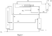
- FIG. 1 An example of a process according to the invention is given in figure 1 .
- the high-pressure part of the process for the production of urea according to figure 1 comprised a second reactor section (R), a CO 2 stripper (S) and a submerged condenser/first reactor section (C) that was placed horizontally. Further the process comprised a medium-pressure absorber (MA) and a low-pressure recovery section where the urea stream (U) was further purified.
- R second reactor section
- S CO 2 stripper
- C submerged condenser/first reactor section
- MA medium-pressure absorber
- U low-pressure recovery section
- a small amount of carbon dioxide was fed to the second reactor section (R).
- a first urea synthesis solution (CS) was reacted with the carbon dioxide to form a second urea synthesis solution (USS) which was sent to stripper (S) and stripped by the addition of heat and with carbon dioxide as a stripping gas.
- S second urea synthesis solution
- S stripper
- S stripping
- SG mixed gas stream
- RG reaction gases
- RG reaction gases coming from the top of the second reactor section (R) fed, via a sparger, to the condenser/first reactor section.
- a carbamate stream (MC) coming from the medium-pressure absorber (MA) was fed together with ammonia.
- This stream was also fed to the condenser/first reactor section with a sparger.
- the first urea synthesis solution formed was sent to the second reactor section and the gases that had not been condensed (CG) were sent to the medium-pressure absorber (MA).
- the gases were absorbed in a low-pressure carbamate stream (LC) and condensed.
- the gases that had not been absorbed (MG) were sent to the low-pressure recovery section.
- the flow from the USS, SG, and CS was a complete gravity flow. No pumps or ejectors were used to move the fluid or gases.
- the high-pressure part of the process for the production of urea according to figure 2 comprised a first and second reactor section (R1 and R2), a CO 2 stripper (S), a falling-film condenser (C) and a high-pressure absorber (HA) and a low-pressure recovery section where the urea stream (U) was further purified.
- a small amount of carbon dioxide was fed to the second reactor section (R2).
- a first urea synthesis solution (RS) coming from the first reactor section (R1) was reacted with the carbon dioxide to form a second urea synthesis solution (USS) which was sent to stripper (S) and stripped by the addition of heat and with carbon dioxide as a stripping gas.
- S second urea synthesis solution
- S stripper
- S stripper
- SG mixed gas stream
- C falling-film condenser
- HC carbamate stream coming from the high-pressure absorber
- HA high-pressure absorber
- the carbamate solution (CS) formed was sent to the first reactor section (R1) together with the gases that had not been condensed.
- Reaction gases (RG) coming from the top of the first and second reactor were sent to the high-pressure absorber (HA).
- HA high-pressure absorber
- the gases were absorbed in a low-pressure carbamate stream (LC) and condensed.
- the gases that had not been absorbed (HG) were sent to the low-pressure recovery section.
- the flow from the USS, SG, CS and RS was a complete gravity flow. No pumps or ejectors were used to move the fluid or gases. Of the total amount of urea formed; 70 wt% was formed in the first reactor section and 30 wt% was formed in the second reactor section.
Landscapes
- Chemical & Material Sciences (AREA)
- Organic Chemistry (AREA)
- Organic Low-Molecular-Weight Compounds And Preparation Thereof (AREA)
Claims (10)
- Verfahren zur Herstellung von Harnstoff aus Ammoniak und Kohlenstoffdioxid in einer Harnstoffanlage,a) wobei die Harnstoffanlage einen Rückgewinnungsabschnitt und einen Hochdrucksyntheseabschnitt, umfassend zwei Reaktorabschnitte, einen Abstreifer und einen Kondensator enthält,b) wobei in dem ersten Reaktorabschnitt eine erste Syntheselösung gebildet wird, die zu dem zweiten Reaktorabschnitt zugeführt wird;c) frisches Kohlenstoffdioxid dem zweiten Reaktorabschnitt zugeführt wird und in dem zweiten Reaktorabschnitt eine zweite Syntheselösung, die dem Abstreifer zugeführt wird, gebildet wird,d) wobei die zweite Syntheselösung unter der Verwendung von Kohlenstoffdioxid als Abstreifgas abgestreift wird und der in dem Abstreifer erhaltene gemischte Gasstrom zu dem Kondensator verschickt wird, zusammen mit frischem Ammoniak und einem Carbamatstrom, und unter der Entfernung von Hitze kondensiert wird,e) woraufhin das in dem Kondensator gebildete Kondensat zu dem ersten Reaktorabschnitt zugeführt wirdf) und der in dem Abstreifer erhaltene Harnstoffstrom in dem Rückgewinnungsabschnitt weiter aufgereinigt wird,g) dadurch gekennzeichnet, dass der Fluss der ersten Syntheselösung von dem ersten Reaktorabschnitt zu dem zweiten Reaktorabschnitt, der Fluss der zweiten Syntheselösung von dem zweiten Reaktorabschnitt zu dem Abstreifer, der Fluss des gemischten Gasstroms von dem Abstreifer zu dem Kondensator und der Fluss des Kondensats von dem Kondensator zu dem ersten Reaktorabschnitt ein Schwerkraftfluss ist,h) wobei der erste Reaktorabschnitt und der Kondensator in einem Behälter kombiniert sind, wobei der Behälter horizontal angeordnet ist,i) wobei in dem ersten Reaktorabschnitt wie auch in dem zweiten Reaktorabschnitt mindestens 20 Gew.-% der Gesamtmenge von Harnstoff in dem Syntheseabschnitt gebildet wird,j) wobei Synthesegas, das in dem zweiten Reaktorabschnitt nicht reagiert hat, aus dem zweiten Reaktorabschnitt entfernt wird.
- Verfahren nach Anspruch 1, wobei sowohl der Abstreifer als auch der zweite Reaktorabschnitt ebenerdig angeordnet sind.
- Verfahren nach Anspruch 1 oder 2, dadurch gekennzeichnet, dass ein Gasfluss vom oberen Ende des zweiten Reaktorabschnitts freigesetzt wird und zu einem Mitteldruckgaswäscher verschickt wird, wobei Ammoniak und Kohlenstoffdioxid, vorhanden in dem Gasfluss, durch Absorption in einem Niederdruck-Carbamatstrom aus dem Gasfluss entfernt werden.
- Verfahren nach Anspruch 1, dadurch gekennzeichnet, dass der Gasfluss vom oberen Ende des zweiten Reaktorabschnitts freigesetzt wird und zu einem Hochdruckgaswäscher verschickt wird, wobei Ammoniak und Kohlenstoffdioxid, vorhanden in dem Gasfluss, durch Absorption in einem Niederdruck-Carbamatstrom aus dem Gasfluss entfernt werden.
- Verfahren nach Anspruch 1, dadurch gekennzeichnet, dass ein Gasfluss vom oberen Ende des ersten Reaktorabschnitts und dem oberen Ende des zweiten Reaktorabschnitts freigesetzt wird und der kombinierte Gasfluss von beiden Reaktorabschnitten zu einem Mitteldruckgaswäscher oder einem Hochdruckgaswäscher verschickt wird, wobei Ammoniak und Kohlenstoffdioxid, vorhanden in dem kombinierten Gasfluss, durch Absorption in einem Niederdruck-Carbamatstrom aus dem Gasfluss entfernt werden.
- Verfahren nach Anspruch 5, wobei der kombinierte Gasfluss zu einem Mitteldruckgaswäscher verschickt wird.
- Verfahren nach Anspruch 1, dadurch gekennzeichnet, dass der Kondensator ein submerser Kondensator ist, der horizontal angeordnet ist.
- Verfahren nach Anspruch 7, dadurch gekennzeichnet, dass der submerse Kondensator vom Mantel- und Röhrentyp ist und dass die Hochdruckflüssigkeiten auf der Mantelseite sind.
- Verfahren nach Anspruch 8, dadurch gekennzeichnet, dass der Mantel- und Röhrenwärmetauscher vom U-Röhrentyp ist.
- Verfahren nach einem der vorhergehenden Ansprüche, dadurch gekennzeichnet, dass mindestens ein Teil der Reaktor- oder Abstreifabschnitte aus einem austenitisch-ferritischen Duplexstahl mit einem Chromgehalt von zwischen 26 und 35 Gew.-% und einem Nickelgehalt von zwischen 3 und 10 Gew.-% hergestellt ist.
Priority Applications (5)
| Application Number | Priority Date | Filing Date | Title |
|---|---|---|---|
| HRP20171925TT HRP20171925T1 (hr) | 2008-05-19 | 2009-05-19 | Postupak za proizvodnju uree iz amonijaka i ugljičnog dioksida |
| EP17192882.3A EP3309144B1 (de) | 2008-05-19 | 2009-05-19 | Verfahren zur herstellung von harnstoff aus ammoniak und kohlendioxid |
| PL09749836T PL2297094T3 (pl) | 2008-05-19 | 2009-05-19 | Sposób wytwarzania mocznika z amoniaku i dwutlenku węgla |
| NO09749836A NO2297094T3 (de) | 2008-05-19 | 2009-05-19 | |
| EP09749836.4A EP2297094B1 (de) | 2008-05-19 | 2009-05-19 | Verfahren zur herstellung von harnstoff aus ammoniak und kohlendioxid |
Applications Claiming Priority (3)
| Application Number | Priority Date | Filing Date | Title |
|---|---|---|---|
| EP08156429A EP2123634A1 (de) | 2008-05-19 | 2008-05-19 | Verfahren zur Herstellung von Harnstoff aus Ammoniak und Kohlendioxid |
| PCT/EP2009/056068 WO2009141346A1 (en) | 2008-05-19 | 2009-05-19 | Process for the production of urea from ammonia and carbon dioxide |
| EP09749836.4A EP2297094B1 (de) | 2008-05-19 | 2009-05-19 | Verfahren zur herstellung von harnstoff aus ammoniak und kohlendioxid |
Related Child Applications (1)
| Application Number | Title | Priority Date | Filing Date |
|---|---|---|---|
| EP17192882.3A Division EP3309144B1 (de) | 2008-05-19 | 2009-05-19 | Verfahren zur herstellung von harnstoff aus ammoniak und kohlendioxid |
Publications (2)
| Publication Number | Publication Date |
|---|---|
| EP2297094A1 EP2297094A1 (de) | 2011-03-23 |
| EP2297094B1 true EP2297094B1 (de) | 2017-09-27 |
Family
ID=39811682
Family Applications (3)
| Application Number | Title | Priority Date | Filing Date |
|---|---|---|---|
| EP08156429A Withdrawn EP2123634A1 (de) | 2008-05-19 | 2008-05-19 | Verfahren zur Herstellung von Harnstoff aus Ammoniak und Kohlendioxid |
| EP09749836.4A Active EP2297094B1 (de) | 2008-05-19 | 2009-05-19 | Verfahren zur herstellung von harnstoff aus ammoniak und kohlendioxid |
| EP17192882.3A Active EP3309144B1 (de) | 2008-05-19 | 2009-05-19 | Verfahren zur herstellung von harnstoff aus ammoniak und kohlendioxid |
Family Applications Before (1)
| Application Number | Title | Priority Date | Filing Date |
|---|---|---|---|
| EP08156429A Withdrawn EP2123634A1 (de) | 2008-05-19 | 2008-05-19 | Verfahren zur Herstellung von Harnstoff aus Ammoniak und Kohlendioxid |
Family Applications After (1)
| Application Number | Title | Priority Date | Filing Date |
|---|---|---|---|
| EP17192882.3A Active EP3309144B1 (de) | 2008-05-19 | 2009-05-19 | Verfahren zur herstellung von harnstoff aus ammoniak und kohlendioxid |
Country Status (14)
| Country | Link |
|---|---|
| US (1) | US8158824B2 (de) |
| EP (3) | EP2123634A1 (de) |
| CN (2) | CN102099328A (de) |
| AU (1) | AU2009249693B2 (de) |
| BR (1) | BRPI0912883B1 (de) |
| CA (1) | CA2724566C (de) |
| EA (1) | EA016786B1 (de) |
| ES (1) | ES2937284T3 (de) |
| HR (1) | HRP20171925T1 (de) |
| MY (1) | MY150057A (de) |
| NO (1) | NO2297094T3 (de) |
| PL (1) | PL2297094T3 (de) |
| UA (1) | UA101500C2 (de) |
| WO (1) | WO2009141346A1 (de) |
Families Citing this family (18)
| Publication number | Priority date | Publication date | Assignee | Title |
|---|---|---|---|---|
| EP2567953A1 (de) * | 2011-09-09 | 2013-03-13 | Urea Casale SA | Kohlenstoffdioxid-abstreifende Harnstoffanlage mit natürlich zirkulierender Syntheseschleife und Verfahren zur Nachrüstung der Anlage |
| AR090886A1 (es) * | 2012-05-03 | 2014-12-10 | Stamicarbon | Metodo de fabricacion de un conjunto de placa de tubo e intercambiador de calor para un reactor o condensador |
| WO2015099530A1 (en) * | 2013-12-27 | 2015-07-02 | Stamicarbon B.V. | Corrosion resistant duplex steel alloy, objects made thereof, and method of making the alloy |
| WO2016099269A1 (en) * | 2014-12-18 | 2016-06-23 | Stamicarbon B.V. | Process for urea production |
| WO2017171546A1 (en) | 2016-03-30 | 2017-10-05 | Stamicarbon B.V. | Urea production with bi-pressurized synthesis |
| EP3366645A1 (de) * | 2017-02-28 | 2018-08-29 | Casale Sa | Ammoniak-harnstoff-integriertes verfahren und anlage |
| EP3398935A1 (de) * | 2017-05-05 | 2018-11-07 | Casale Sa | Verfahren und anlage zur synthese von harnstoff |
| PE20220305A1 (es) * | 2019-06-07 | 2022-03-09 | Stamicarbon | Planta de urea con extractor y metodo de extraccion |
| EP3766865A1 (de) * | 2019-07-18 | 2021-01-20 | Casale Sa | Verfahren zur synthese von harnstoff |
| BR112022016664A2 (pt) | 2020-02-25 | 2022-10-11 | Casale Sa | Processo e planta para a síntese de ureia |
| CN112090278A (zh) * | 2020-09-30 | 2020-12-18 | 河南弘康环保科技有限公司 | 一种高纯车用尿素溶液的制备方法及其系统 |
| CN112110835A (zh) * | 2020-09-30 | 2020-12-22 | 河南弘康环保科技有限公司 | 一种防止尿素缩二脲、三聚氰酸和三聚氰胺中间产物生成的车用尿素及其制备方法 |
| CN112094207A (zh) * | 2020-09-30 | 2020-12-18 | 河南弘康环保科技有限公司 | 一种低甲醛车用尿素溶液的制备方法 |
| CN112316722A (zh) * | 2020-11-13 | 2021-02-05 | 河南弘康环保科技有限公司 | 一种添加多种活性剂的防冻保质型汽车尿素液制备方法 |
| CN112316723A (zh) * | 2020-11-13 | 2021-02-05 | 河南弘康环保科技有限公司 | 一种高效解决结晶堵塞的车用尿素溶液 |
| HRP20250240T1 (hr) | 2021-06-11 | 2025-05-23 | Stamicarbon B.V. | Proizvodnja uree s trostrukim mp strujama |
| AU2024375057A1 (en) | 2023-11-07 | 2026-04-02 | Casale Sa | A co2-stripping urea process and plant |
| WO2025198471A1 (en) | 2024-03-20 | 2025-09-25 | Stamicarbon B.V. | Urea plant with modified condenser and modified reactor internals |
Family Cites Families (8)
| Publication number | Priority date | Publication date | Assignee | Title |
|---|---|---|---|---|
| BE527914A (de) | 1953-04-15 | |||
| NL8400839A (nl) | 1984-03-16 | 1985-10-16 | Unie Van Kunstmestfab Bv | Werkwijze voor de bereiding van ureum. |
| NL8800284A (nl) * | 1988-02-08 | 1989-09-01 | Stamicarbon | Werkwijze voor de bereiding van ureum. |
| US5767313A (en) | 1995-05-23 | 1998-06-16 | Dsm N.V. | Method for the preparation of urea |
| JP3987607B2 (ja) * | 1996-10-07 | 2007-10-10 | 東洋エンジニアリング株式会社 | 改良された尿素合成方法および装置 |
| NL1011123C2 (nl) | 1999-01-25 | 2000-07-27 | Dsm Nv | Werkwijze voor de bereiding van ureum. |
| US6287404B1 (en) * | 1999-12-13 | 2001-09-11 | The United States Of America As Represented By The Administrator Of The National Aeronautics And Space Administration | Adhesive bubble removal method and apparatus for fiber optic applications |
| NL1014756C2 (nl) | 2000-03-27 | 2001-09-28 | Dsm Nv | Reactor en werkwijze voor de bereiding van ureum. |
-
2008
- 2008-05-19 EP EP08156429A patent/EP2123634A1/de not_active Withdrawn
-
2009
- 2009-05-19 NO NO09749836A patent/NO2297094T3/no unknown
- 2009-05-19 EP EP09749836.4A patent/EP2297094B1/de active Active
- 2009-05-19 WO PCT/EP2009/056068 patent/WO2009141346A1/en not_active Ceased
- 2009-05-19 EA EA201001806A patent/EA016786B1/ru not_active IP Right Cessation
- 2009-05-19 EP EP17192882.3A patent/EP3309144B1/de active Active
- 2009-05-19 CA CA2724566A patent/CA2724566C/en active Active
- 2009-05-19 HR HRP20171925TT patent/HRP20171925T1/hr unknown
- 2009-05-19 AU AU2009249693A patent/AU2009249693B2/en active Active
- 2009-05-19 UA UAA201015112A patent/UA101500C2/ru unknown
- 2009-05-19 ES ES17192882T patent/ES2937284T3/es active Active
- 2009-05-19 CN CN2009801283132A patent/CN102099328A/zh active Pending
- 2009-05-19 MY MYPI2010005415A patent/MY150057A/en unknown
- 2009-05-19 CN CN201610168869.6A patent/CN105801451A/zh active Pending
- 2009-05-19 US US12/993,824 patent/US8158824B2/en active Active
- 2009-05-19 PL PL09749836T patent/PL2297094T3/pl unknown
- 2009-05-19 BR BRPI0912883-2A patent/BRPI0912883B1/pt active IP Right Grant
Non-Patent Citations (1)
| Title |
|---|
| "A LOWER COST DESIGN FOR UREA", NITROGEN, BRITISH SULPHUR CO, LONDON, GB, no. 222, 1 July 1996 (1996-07-01), pages 29 - 31, XP000598593, ISSN: 0029-0777 * |
Also Published As
| Publication number | Publication date |
|---|---|
| EA201001806A1 (ru) | 2011-04-29 |
| ES2937284T3 (es) | 2023-03-27 |
| EP3309144B1 (de) | 2022-12-21 |
| UA101500C2 (ru) | 2013-04-10 |
| AU2009249693A1 (en) | 2009-11-26 |
| HRP20171925T1 (hr) | 2018-02-23 |
| NO2297094T3 (de) | 2018-02-24 |
| EP2123634A1 (de) | 2009-11-25 |
| CA2724566C (en) | 2016-07-05 |
| PL2297094T3 (pl) | 2018-04-30 |
| US20110160486A1 (en) | 2011-06-30 |
| BRPI0912883A2 (pt) | 2015-10-20 |
| AU2009249693B2 (en) | 2013-02-21 |
| EA016786B1 (ru) | 2012-07-30 |
| EP3309144A1 (de) | 2018-04-18 |
| CN105801451A (zh) | 2016-07-27 |
| US8158824B2 (en) | 2012-04-17 |
| CA2724566A1 (en) | 2009-11-26 |
| WO2009141346A1 (en) | 2009-11-26 |
| BRPI0912883B1 (pt) | 2018-05-15 |
| EP2297094A1 (de) | 2011-03-23 |
| CN102099328A (zh) | 2011-06-15 |
| MY150057A (en) | 2013-11-29 |
Similar Documents
| Publication | Publication Date | Title |
|---|---|---|
| EP2297094B1 (de) | Verfahren zur herstellung von harnstoff aus ammoniak und kohlendioxid | |
| US10376859B2 (en) | Urea production with bi-pressurized synthesis | |
| JP7094453B2 (ja) | 尿素製造プロセス及び低圧回収部における熱統合を有するプラント | |
| EP2279170B1 (de) | Verfahren zum erhöhen der kapazität einer bestehenden harnstoffanlage | |
| EP2297093B1 (de) | Verfahren zur herstellung von harnstoff aus ammoniak und kohlendioxid | |
| CN105026365A (zh) | 尿素合成方法和设备 | |
| CA2627827A1 (en) | Method for modernizing a urea production plant | |
| AU2009249691B2 (en) | Process for the production of urea from ammonia and carbon dioxide | |
| EP1594820B1 (de) | Verfahren und vorrichtung zur herstellung von harnstoff | |
| MXPA06013105A (es) | Proceso para la produccion de urea y planta relacionada. |
Legal Events
| Date | Code | Title | Description |
|---|---|---|---|
| PUAI | Public reference made under article 153(3) epc to a published international application that has entered the european phase |
Free format text: ORIGINAL CODE: 0009012 |
|
| 17P | Request for examination filed |
Effective date: 20101213 |
|
| AK | Designated contracting states |
Kind code of ref document: A1 Designated state(s): AT BE BG CH CY CZ DE DK EE ES FI FR GB GR HR HU IE IS IT LI LT LU LV MC MK MT NL NO PL PT RO SE SI SK TR |
|
| AX | Request for extension of the european patent |
Extension state: AL BA RS |
|
| RIN1 | Information on inventor provided before grant (corrected) |
Inventor name: MENNEN, JOHANNES HENRICUS Inventor name: MEESSEN, JOZEF HUBERT Inventor name: GEVERS, LAMBERTUS WILHELMUS |
|
| DAX | Request for extension of the european patent (deleted) | ||
| RAP1 | Party data changed (applicant data changed or rights of an application transferred) |
Owner name: STAMICARBON B.V. |
|
| 17Q | First examination report despatched |
Effective date: 20140204 |
|
| TPAC | Observations filed by third parties |
Free format text: ORIGINAL CODE: EPIDOSNTIPA |
|
| TPAC | Observations filed by third parties |
Free format text: ORIGINAL CODE: EPIDOSNTIPA |
|
| TPAC | Observations filed by third parties |
Free format text: ORIGINAL CODE: EPIDOSNTIPA |
|
| TPAC | Observations filed by third parties |
Free format text: ORIGINAL CODE: EPIDOSNTIPA |
|
| TPAC | Observations filed by third parties |
Free format text: ORIGINAL CODE: EPIDOSNTIPA |
|
| GRAP | Despatch of communication of intention to grant a patent |
Free format text: ORIGINAL CODE: EPIDOSNIGR1 |
|
| STAA | Information on the status of an ep patent application or granted ep patent |
Free format text: STATUS: GRANT OF PATENT IS INTENDED |
|
| GRAS | Grant fee paid |
Free format text: ORIGINAL CODE: EPIDOSNIGR3 |
|
| GRAA | (expected) grant |
Free format text: ORIGINAL CODE: 0009210 |
|
| STAA | Information on the status of an ep patent application or granted ep patent |
Free format text: STATUS: THE PATENT HAS BEEN GRANTED |
|
| INTG | Intention to grant announced |
Effective date: 20170816 |
|
| AK | Designated contracting states |
Kind code of ref document: B1 Designated state(s): AT BE BG CH CY CZ DE DK EE ES FI FR GB GR HR HU IE IS IT LI LT LU LV MC MK MT NL NO PL PT RO SE SI SK TR |
|
| REG | Reference to a national code |
Ref country code: GB Ref legal event code: FG4D |
|
| REG | Reference to a national code |
Ref country code: CH Ref legal event code: EP |
|
| REG | Reference to a national code |
Ref country code: AT Ref legal event code: REF Ref document number: 931792 Country of ref document: AT Kind code of ref document: T Effective date: 20171015 |
|
| REG | Reference to a national code |
Ref country code: IE Ref legal event code: FG4D |
|
| REG | Reference to a national code |
Ref country code: DE Ref legal event code: R096 Ref document number: 602009048569 Country of ref document: DE |
|
| REG | Reference to a national code |
Ref country code: HR Ref legal event code: TUEP Ref document number: P20171925 Country of ref document: HR Ref country code: RO Ref legal event code: EPE |
|
| REG | Reference to a national code |
Ref country code: NL Ref legal event code: FP |
|
| PG25 | Lapsed in a contracting state [announced via postgrant information from national office to epo] |
Ref country code: FI Free format text: LAPSE BECAUSE OF FAILURE TO SUBMIT A TRANSLATION OF THE DESCRIPTION OR TO PAY THE FEE WITHIN THE PRESCRIBED TIME-LIMIT Effective date: 20170927 Ref country code: LT Free format text: LAPSE BECAUSE OF FAILURE TO SUBMIT A TRANSLATION OF THE DESCRIPTION OR TO PAY THE FEE WITHIN THE PRESCRIBED TIME-LIMIT Effective date: 20170927 Ref country code: SE Free format text: LAPSE BECAUSE OF FAILURE TO SUBMIT A TRANSLATION OF THE DESCRIPTION OR TO PAY THE FEE WITHIN THE PRESCRIBED TIME-LIMIT Effective date: 20170927 |
|
| REG | Reference to a national code |
Ref country code: LT Ref legal event code: MG4D |
|
| REG | Reference to a national code |
Ref country code: AT Ref legal event code: MK05 Ref document number: 931792 Country of ref document: AT Kind code of ref document: T Effective date: 20170927 |
|
| REG | Reference to a national code |
Ref country code: HR Ref legal event code: T1PR Ref document number: P20171925 Country of ref document: HR |
|
| REG | Reference to a national code |
Ref country code: NO Ref legal event code: T2 Effective date: 20170927 |
|
| PG25 | Lapsed in a contracting state [announced via postgrant information from national office to epo] |
Ref country code: LV Free format text: LAPSE BECAUSE OF FAILURE TO SUBMIT A TRANSLATION OF THE DESCRIPTION OR TO PAY THE FEE WITHIN THE PRESCRIBED TIME-LIMIT Effective date: 20170927 Ref country code: GR Free format text: LAPSE BECAUSE OF FAILURE TO SUBMIT A TRANSLATION OF THE DESCRIPTION OR TO PAY THE FEE WITHIN THE PRESCRIBED TIME-LIMIT Effective date: 20171228 Ref country code: BG Free format text: LAPSE BECAUSE OF FAILURE TO SUBMIT A TRANSLATION OF THE DESCRIPTION OR TO PAY THE FEE WITHIN THE PRESCRIBED TIME-LIMIT Effective date: 20171227 |
|
| PG25 | Lapsed in a contracting state [announced via postgrant information from national office to epo] |
Ref country code: ES Free format text: LAPSE BECAUSE OF FAILURE TO SUBMIT A TRANSLATION OF THE DESCRIPTION OR TO PAY THE FEE WITHIN THE PRESCRIBED TIME-LIMIT Effective date: 20170927 |
|
| PG25 | Lapsed in a contracting state [announced via postgrant information from national office to epo] |
Ref country code: IS Free format text: LAPSE BECAUSE OF FAILURE TO SUBMIT A TRANSLATION OF THE DESCRIPTION OR TO PAY THE FEE WITHIN THE PRESCRIBED TIME-LIMIT Effective date: 20180127 Ref country code: EE Free format text: LAPSE BECAUSE OF FAILURE TO SUBMIT A TRANSLATION OF THE DESCRIPTION OR TO PAY THE FEE WITHIN THE PRESCRIBED TIME-LIMIT Effective date: 20170927 Ref country code: AT Free format text: LAPSE BECAUSE OF FAILURE TO SUBMIT A TRANSLATION OF THE DESCRIPTION OR TO PAY THE FEE WITHIN THE PRESCRIBED TIME-LIMIT Effective date: 20170927 Ref country code: SK Free format text: LAPSE BECAUSE OF FAILURE TO SUBMIT A TRANSLATION OF THE DESCRIPTION OR TO PAY THE FEE WITHIN THE PRESCRIBED TIME-LIMIT Effective date: 20170927 |
|
| REG | Reference to a national code |
Ref country code: DE Ref legal event code: R097 Ref document number: 602009048569 Country of ref document: DE |
|
| PG25 | Lapsed in a contracting state [announced via postgrant information from national office to epo] |
Ref country code: DK Free format text: LAPSE BECAUSE OF FAILURE TO SUBMIT A TRANSLATION OF THE DESCRIPTION OR TO PAY THE FEE WITHIN THE PRESCRIBED TIME-LIMIT Effective date: 20170927 |
|
| PLBE | No opposition filed within time limit |
Free format text: ORIGINAL CODE: 0009261 |
|
| STAA | Information on the status of an ep patent application or granted ep patent |
Free format text: STATUS: NO OPPOSITION FILED WITHIN TIME LIMIT |
|
| 26N | No opposition filed |
Effective date: 20180628 |
|
| PG25 | Lapsed in a contracting state [announced via postgrant information from national office to epo] |
Ref country code: SI Free format text: LAPSE BECAUSE OF FAILURE TO SUBMIT A TRANSLATION OF THE DESCRIPTION OR TO PAY THE FEE WITHIN THE PRESCRIBED TIME-LIMIT Effective date: 20170927 |
|
| GBPC | Gb: european patent ceased through non-payment of renewal fee |
Effective date: 20180519 |
|
| REG | Reference to a national code |
Ref country code: BE Ref legal event code: MM Effective date: 20180531 |
|
| PG25 | Lapsed in a contracting state [announced via postgrant information from national office to epo] |
Ref country code: MC Free format text: LAPSE BECAUSE OF FAILURE TO SUBMIT A TRANSLATION OF THE DESCRIPTION OR TO PAY THE FEE WITHIN THE PRESCRIBED TIME-LIMIT Effective date: 20170927 |
|
| REG | Reference to a national code |
Ref country code: IE Ref legal event code: MM4A |
|
| PG25 | Lapsed in a contracting state [announced via postgrant information from national office to epo] |
Ref country code: LU Free format text: LAPSE BECAUSE OF NON-PAYMENT OF DUE FEES Effective date: 20180519 |
|
| PG25 | Lapsed in a contracting state [announced via postgrant information from national office to epo] |
Ref country code: FR Free format text: LAPSE BECAUSE OF NON-PAYMENT OF DUE FEES Effective date: 20180531 Ref country code: GB Free format text: LAPSE BECAUSE OF NON-PAYMENT OF DUE FEES Effective date: 20180519 Ref country code: IE Free format text: LAPSE BECAUSE OF NON-PAYMENT OF DUE FEES Effective date: 20180519 |
|
| REG | Reference to a national code |
Ref country code: HR Ref legal event code: ODRP Ref document number: P20171925 Country of ref document: HR Payment date: 20190429 Year of fee payment: 11 |
|
| PG25 | Lapsed in a contracting state [announced via postgrant information from national office to epo] |
Ref country code: BE Free format text: LAPSE BECAUSE OF NON-PAYMENT OF DUE FEES Effective date: 20180531 |
|
| PG25 | Lapsed in a contracting state [announced via postgrant information from national office to epo] |
Ref country code: MT Free format text: LAPSE BECAUSE OF NON-PAYMENT OF DUE FEES Effective date: 20180519 |
|
| PG25 | Lapsed in a contracting state [announced via postgrant information from national office to epo] |
Ref country code: HU Free format text: LAPSE BECAUSE OF FAILURE TO SUBMIT A TRANSLATION OF THE DESCRIPTION OR TO PAY THE FEE WITHIN THE PRESCRIBED TIME-LIMIT; INVALID AB INITIO Effective date: 20090519 Ref country code: PT Free format text: LAPSE BECAUSE OF FAILURE TO SUBMIT A TRANSLATION OF THE DESCRIPTION OR TO PAY THE FEE WITHIN THE PRESCRIBED TIME-LIMIT Effective date: 20170927 |
|
| REG | Reference to a national code |
Ref country code: HR Ref legal event code: ODRP Ref document number: P20171925 Country of ref document: HR Payment date: 20200514 Year of fee payment: 12 |
|
| PG25 | Lapsed in a contracting state [announced via postgrant information from national office to epo] |
Ref country code: CY Free format text: LAPSE BECAUSE OF FAILURE TO SUBMIT A TRANSLATION OF THE DESCRIPTION OR TO PAY THE FEE WITHIN THE PRESCRIBED TIME-LIMIT Effective date: 20170927 Ref country code: MK Free format text: LAPSE BECAUSE OF NON-PAYMENT OF DUE FEES Effective date: 20170927 |
|
| REG | Reference to a national code |
Ref country code: HR Ref legal event code: ODRP Ref document number: P20171925 Country of ref document: HR Payment date: 20210513 Year of fee payment: 13 |
|
| REG | Reference to a national code |
Ref country code: HR Ref legal event code: ODRP Ref document number: P20171925 Country of ref document: HR Payment date: 20220513 Year of fee payment: 14 |
|
| REG | Reference to a national code |
Ref country code: HR Ref legal event code: ODRP Ref document number: P20171925 Country of ref document: HR Payment date: 20230518 Year of fee payment: 15 |
|
| P01 | Opt-out of the competence of the unified patent court (upc) registered |
Effective date: 20230516 |
|
| REG | Reference to a national code |
Ref country code: HR Ref legal event code: ODRP Ref document number: P20171925 Country of ref document: HR Payment date: 20240510 Year of fee payment: 16 |
|
| PGFP | Annual fee paid to national office [announced via postgrant information from national office to epo] |
Ref country code: NL Payment date: 20250401 Year of fee payment: 17 |
|
| REG | Reference to a national code |
Ref country code: HR Ref legal event code: ODRP Ref document number: P20171925 Country of ref document: HR Payment date: 20250508 Year of fee payment: 17 |
|
| PGFP | Annual fee paid to national office [announced via postgrant information from national office to epo] |
Ref country code: DE Payment date: 20250521 Year of fee payment: 17 Ref country code: PL Payment date: 20250428 Year of fee payment: 17 |
|
| PGFP | Annual fee paid to national office [announced via postgrant information from national office to epo] |
Ref country code: NO Payment date: 20250523 Year of fee payment: 17 |
|
| PGFP | Annual fee paid to national office [announced via postgrant information from national office to epo] |
Ref country code: IT Payment date: 20250527 Year of fee payment: 17 |
|
| PGFP | Annual fee paid to national office [announced via postgrant information from national office to epo] |
Ref country code: HR Payment date: 20250508 Year of fee payment: 17 |
|
| PGFP | Annual fee paid to national office [announced via postgrant information from national office to epo] |
Ref country code: CH Payment date: 20250601 Year of fee payment: 17 |
|
| PGFP | Annual fee paid to national office [announced via postgrant information from national office to epo] |
Ref country code: RO Payment date: 20250514 Year of fee payment: 17 |
|
| PGFP | Annual fee paid to national office [announced via postgrant information from national office to epo] |
Ref country code: TR Payment date: 20250512 Year of fee payment: 17 |
|
| PGFP | Annual fee paid to national office [announced via postgrant information from national office to epo] |
Ref country code: CZ Payment date: 20250514 Year of fee payment: 17 |