EP2297421B2 - Mécanisme d'entraînement de porte - Google Patents
Mécanisme d'entraînement de porte Download PDFInfo
- Publication number
- EP2297421B2 EP2297421B2 EP09737752.7A EP09737752A EP2297421B2 EP 2297421 B2 EP2297421 B2 EP 2297421B2 EP 09737752 A EP09737752 A EP 09737752A EP 2297421 B2 EP2297421 B2 EP 2297421B2
- Authority
- EP
- European Patent Office
- Prior art keywords
- door
- arm
- pivot
- support
- pivot arm
- Prior art date
- Legal status (The legal status is an assumption and is not a legal conclusion. Google has not performed a legal analysis and makes no representation as to the accuracy of the status listed.)
- Active
Links
Images

Classifications
-
- E—FIXED CONSTRUCTIONS
- E06—DOORS, WINDOWS, SHUTTERS, OR ROLLER BLINDS IN GENERAL; LADDERS
- E06B—FIXED OR MOVABLE CLOSURES FOR OPENINGS IN BUILDINGS, VEHICLES, FENCES OR LIKE ENCLOSURES IN GENERAL, e.g. DOORS, WINDOWS, BLINDS, GATES
- E06B11/00—Means for allowing passage through fences, barriers or the like, e.g. stiles
- E06B11/08—Turnstiles; Gates for control of entry or exit of persons, e.g. in supermarkets
- E06B11/085—Turnstiles; Gates for control of entry or exit of persons, e.g. in supermarkets non-rotary or with a limited angle of rotation, e.g. 90°
-
- E—FIXED CONSTRUCTIONS
- E05—LOCKS; KEYS; WINDOW OR DOOR FITTINGS; SAFES
- E05F—DEVICES FOR MOVING WINGS INTO OPEN OR CLOSED POSITION; CHECKS FOR WINGS; WING FITTINGS NOT OTHERWISE PROVIDED FOR, CONCERNED WITH THE FUNCTIONING OF THE WING
- E05F15/00—Power-operated mechanisms for wings
- E05F15/50—Power-operated mechanisms for wings using fluid-pressure actuators
- E05F15/53—Power-operated mechanisms for wings using fluid-pressure actuators for swinging wings
-
- E—FIXED CONSTRUCTIONS
- E05—LOCKS; KEYS; WINDOW OR DOOR FITTINGS; SAFES
- E05F—DEVICES FOR MOVING WINGS INTO OPEN OR CLOSED POSITION; CHECKS FOR WINGS; WING FITTINGS NOT OTHERWISE PROVIDED FOR, CONCERNED WITH THE FUNCTIONING OF THE WING
- E05F15/00—Power-operated mechanisms for wings
- E05F15/60—Power-operated mechanisms for wings using electrical actuators
- E05F15/603—Power-operated mechanisms for wings using electrical actuators using rotary electromotors
- E05F15/611—Power-operated mechanisms for wings using electrical actuators using rotary electromotors for swinging wings
- E05F15/63—Power-operated mechanisms for wings using electrical actuators using rotary electromotors for swinging wings operated by swinging arms
-
- E—FIXED CONSTRUCTIONS
- E05—LOCKS; KEYS; WINDOW OR DOOR FITTINGS; SAFES
- E05Y—INDEXING SCHEME ASSOCIATED WITH SUBCLASSES E05D AND E05F, RELATING TO CONSTRUCTION ELEMENTS, ELECTRIC CONTROL, POWER SUPPLY, POWER SIGNAL OR TRANSMISSION, USER INTERFACES, MOUNTING OR COUPLING, DETAILS, ACCESSORIES, AUXILIARY OPERATIONS NOT OTHERWISE PROVIDED FOR, APPLICATION THEREOF
- E05Y2900/00—Application of doors, windows, wings or fittings thereof
- E05Y2900/40—Application of doors, windows, wings or fittings thereof for gates
Definitions
- the present invention relates to a door drive with a carrier to which a pivot arm connected to a door and adjusting means are each rotatably articulated, wherein the actuating means on the pivot arm engage such that it is pivotable about a pivot axis by actuation of the adjusting means.
- Such door drives are provided for example for use in passage barriers see eg DE 20 2005 015 373 U , Such passage barriers are used in all places where the passage of people in a separated area or from a separate area to be regulated out.
- various configurations of the door elements used are known, which include various shapes, such as rectangular shapes, triangular or various other shapes.
- the various forms require and enable this in some cases different movement pattern, which in each case a specific door element and a correspondingly adapted door drive must be assigned.
- the present invention seeks to provide a door drive, which also requires very little space, but still waives the use of a rail guide. Furthermore, such a door drive should allow to use different forms of door leaves with one and the same drive.
- a door drive has a carrier which is essentially to be regarded as a frame of the construction.
- the carrier is equipped with a pivot arm, which is assigned to the carrier via a hinge.
- the swivel arm is swingable back and forth on the carrier.
- the pivoting of the swivel arm is performed by means of adjusting means, which are conceivable in different embodiments.
- a preferred embodiment of the actuating means is a pivot lever, which in turn is associated with the carrier rotatable.
- the pivot lever further associated with drive means which can rotate the pivot lever in a semicircle about a drive axis around.
- the free end of the pivot lever engages in a linear guide of the pivot arm, which can be realized for example in the form of a slot, so that the free ends of the two pivot elements are interconnected such that a rotation of the pivot lever implemented in a forward and backward movement of the pivot arm becomes.
- the pivot lever has at its end an engagement means, depending on the design of the linear guide in the form of a sliding roller or a ball-bearing carriage, so that this engagement is slidably received in the linear guide. If the pivot lever connected to the pivot arm via a hinge connection, the resulting connection would be set in a predetermined position.
- the slot is used in this context to limit the pivoting movement of the pivot lever.
- the rotation of the pivot lever ends at the point at which the engaging element has been guided to the stop of the linear guide, wherein the pivot arm and pivot lever are aligned with each other so that this position represents a front deflection position of the door element. In this front deflection position of the door element, this is in a locked position.
- the engaging element moves in the linear guide first in a lowest position and then back to the aforementioned stop position, which in turn forms the stop in the rear stop position of the door element in this case. In this rear stop position of the door element, this is in a release position.
- a linear drive or a piston drive may be provided, for example in the form of a hydraulic cylinder, which is also rotatably suspended from the carrier and is pivotally connected at its free end to the pivot arm.
- the door leaf is connected to the pivoting arm along a fastening edge, that is, it is thus immovably joined thereto.
- the door element, or the door leaf thus follows exactly the movement of the swivel arm.
- Such an arrangement is particularly suitable for the shape of the triangle for the door leaf, so that the door leaf substantially fills the area of space covered by the pivoting arm in the course of a movement sequence. Due to this shape, the door in its release position will completely release the passageway, although the door is moved in a pivoting movement out of the passageway.
- the door drive is associated with an additional support arm, which is also hingedly connected to the carrier.
- the door leaf is connected in a point-like manner to the swivel arm only in a swivel joint, whereby it can be rotated relative to the swivel arm.
- the door is attached to the support arm so that the door is kept defined.
- the rectangular shape of a door leaf is particularly suitable here after a substantially parallel trailing rear edge of the door leaf causes the effect of a sliding door is at least largely modeled.
- the door must therefore not be connected directly to the pivot arm or the support arm; Rather, it is possible to provide a retaining rail, which has the corresponding fastening means. This retaining rail can in turn be connected to the door leaf, so that in this way the door leaf is easily replaceable if necessary.
- An additional lateral guidance of the door leaves can be realized in that the swivel arm is associated with a side guide which engages around a leading edge of the carrier.
- the corresponding edge is adapted to the movement pattern of the pivot arm, so that the side guide is always in engagement with the leading edge.
- the leading edge can have a high point, which marks the point of the largest elevation of the door. This makes it possible that the door automatically runs in an off position after exceeding this high point due to their positional energy. It can be assigned to the defined positioning of the door in the event of power failure, an additional means for overcoming the high point, so that care is taken that the door always assumes the expected position in this case.
- a door which is used as a passage barrier, must muster a certain force, which is the attempt to open it, is brought.
- This is applied in a simple embodiment only by the drive of the pivot arm, which, however, can be reinforced by a magnet between the pivot arm and the carrier or between the pivot lever and support is arranged, the door in its closed position due to additional magnetic energy in their Holding position.
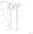
- FIG. 1 shows a door drive 1, which can move a door 2 in a locking position 12 and a release position 13.
- the door leaf 2 is attached to a pivot arm 4, which in turn is connected via a pivot axis 8 with a carrier 3 associated with the door drive 1.
- the door 2 is thereby moved to a release position 13, that the pivot arm 4 from the position shown by the door 2 is pivoted away.
- a pivot lever 5 is provided such that it in turn is pivotable about a drive shaft 9 and engages with a provided at its free end engaging means 7 in a designed as a slot 6 linear guide of the swing arm 4.
- the engagement means 7 moves in the slot 6 both downwards, as well as to the side, so that the pivot arm 4 tracks the predetermined by the pivot lever 5 rotation.
- the pivot arm 4 is moved in an arc about the pivot axis 8 around and the door 2 thus spent from a locking position 12 in a release position 13.
- the pivot arm 4 in this case additionally has a side guide 11, which surrounds a guide edge 18 of the carrier 3 and thereby prevents jumping of the pivot arm 4 of the engagement means 7 of the pivot lever 5.
- the leading edge 18 of the carrier 3 is formed for this purpose according to the arc described by the pivot arm 4. In this way, it is ensured that the side guide 11 always remains in engagement with the edge of the carrier 3.
- this side touching takes on 11 directed against the door pressure force, which is met with an intrusion.
- a division of functions between drive and guide is realized, so that the drive itself does not have to absorb the pressure force.
- a powerless open position of the door drive 1 is realized in that in the case of a power-off, the door is moved along the leading edge 18 due to its gravity in the open position.
- the leading edge 18 has a high point, which can be overcome if necessary in the event of a power failure by means of suitable means, such as a battery-powered auxiliary drive, whereby the door 2 then moves into the open position.
- the drive 10 of the pivot lever 5 is realized by an electric motor, so that an automatic operation of the door drive is made possible.
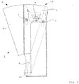
- FIG. 2 again shows the previously illustrated embodiment of the door drive 1, wherein a solid representation corresponds to a locking position 12, while another position of the door drive 1 is shown in dashed lines.
- the door leaf 2 In this second position, the door leaf 2 is in a release position 13, that is, withdrawn from the passageway to which the respective door drive 1 is assigned.
- the engagement means 7 of the pivot lever 5 is located in both extreme positions in each case in the uppermost position of the elongated hole 6, wherein the movement sequence is such that upon rotation of the pivot lever 5, the engagement means 7 initially moves in the slot 6 down, then in an intermediate position reaches the lowest point and then again in the slot 6 moves upward until it again reaches the upper stop, in which the release position 13 is reached.
- the door leaf 2 is shaped in such a way that it substantially corresponds to the area swept by the swivel arm 4, so that the door leaf 2 is flush with the support 3 in the release position 13, so that it is completely withdrawn from the passageway in this position is.
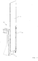
- FIG. 3 shows an embodiment of a door drive 1 according to the invention, which is equipped with a rectangular door leaf 2.
- a rectangular door panel 2 may cover a higher area after a door panel 2 has been replaced in accordance with FIGS FIGS. 1 and 2 in a higher version would have to be shaped such that an upper portion of the door leaf 2 would be very wide, a lower portion, however, would be very narrow. This would release a relatively large opening in the middle between two doors, by which an effective blocking of the area secured by the passage barrier would no longer be guaranteed.
- it makes sense to provide a rectangular door, which ideally should be able to be directly inserted and ejected due to the space required for a pivoting preferred dimensions.
- the door leaf 2 is connected in the corresponding device only at a rotary joint with the pivot arm 4. Characterized in that a connection of the door leaf 2 with the pivot arm 4 is not provided along the entire edge, a detached from the rotational movement of the pivot arm 4 movement form for the door 2 is possible.
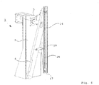
- FIG. 4 shows the door drive 1 according to FIG. 3 , With the door 2 was removed for clarity.
- the pivot arm 4 is associated with an additional support arm 15, which in turn is rotatably mounted on the carrier 3.
- a retaining rail 14 is articulated by means of a slidingly inserted in a linear guide 17 connecting means 16 movable engagement means 7, which is hingedly connected at its other end to the pivot arm 4.
- a connecting means 16 is provided, which is pivotally connected both to the pivot arm 4, and with the support arm 15.
- the pivot arm 4 is moved in the same manner in a forward position, as in connection with the embodiments according to FIGS. 1 and 2 shown, so only the connected to the pivot arm 4 point of the door leaf 2 and the support rail 14, the movement of the swing arm 4 to understand.
- the support arm 15 is pulled behind the pivot arm 4, so that the attached part of the door leaf 2 of the movement of the pivot arm 4 follows, but is offset so that the door 2 is held substantially perpendicular in the course of his movement , This creates the impression of a displacement of the door leaf 2 in a locking position 12, after the caused by the pivot arm 4 slight increase the door leaf 2 with a correspondingly long pivot arm 4 moves only on the edge of the perceptibility.
- FIG. 5 finally shows the door drive 1 in a locking position 12, in which the itself to be provided with a door 2 holding rail 14 has arrived in a forward position.
- the pivot lever 5 is in a stop position in which he holds the pivot arm 4 in turn in a disengaged position. Also in this position, the holding rail 14 is arranged substantially vertically, as it has been previously in the engaged position, ie the release position 13.
- variable door drive which on the one hand solves the problem of creating a sliding effect for the door of a turnstile, which essentially works to save space and on the other makes it possible to different door with one and the same drive unit by minor structural changes use.
Landscapes
- Engineering & Computer Science (AREA)
- Civil Engineering (AREA)
- Structural Engineering (AREA)
- Power-Operated Mechanisms For Wings (AREA)
Claims (10)
- Entraînement de porte avec une console (3) à laquelle un bras pivotant (4) et des moyens de réglage reliés à un vantail de porte (2) sont respectivement rattachés avec possibilité de rotation, de telle sorte que les moyens de réglage se mettent en prise avec le bras pivotant (4) de manière qu'il puisse être tourné autour d'un axe de rotation (8) par l'actionnement des moyens de réglage, dans lequel les moyens de réglage comprennent un levier pivotant (5) qui peut tourner autour d'un axe d'entraînement (9) à l'aide de moyens d'entraînement (10) associés à la console (3), une extrémité libre du levier pivotant (5) possédant des moyens d'engagement (7) qui se mettent en prise de façon coulissante dans un guide linéaire du bras pivotant (4), caractérisé en ce que le vantail de porte (2) possède une suspension en deux points, le vantail de porte (2) étant relié respectivement de façon articulée au bras pivotant (4) et à un bras de support (15) relié avec possibilité de rotation à la console (3).
- Entraînement de porte selon la revendication 1, caractérisé en ce que le bras de support (15) possède des moyens de liaison (16) qui sont reliés de façon articulée au bras pivotant (4) et au bras de support (15), de telle sorte que la liaison entre le vantail de porte (2) et le bras de support (15) est formée par un moyen d'engagement qui se met en prise de façon coulissante dans un guide linéaire (17) du vantail de porte (2).
- Entraînement de porte selon l'une des revendications précédentes, caractérisé en ce que le vantail de porte (2) est essentiellement rectangulaire.
- Entraînement de porte selon l'une des revendications précédentes, caractérisé en ce que le vantail de porte (2) est retenu par un rail de maintien (14) qui forme l'attache au bras pivotant (4) ou au bras de support (15).
- Entraînement de porte selon l'une des revendications précédentes, caractérisé en ce qu'au moins un guide latéral (11) est associé à au bras pivotant (4) et/ou au rail de maintien (14), lequel guide enserre un bord de guidage (18) de la console (3) adapté au mode de mouvement du bras pivotant (4) et qui peut coulisser le long de ce bord.
- Entraînement de porte selon la revendication 5, caractérisé en ce que ledit au moins un bord de guidage (18) de la console (3) possède un point de maximum et des moyens pour dépasser le point de maximum en cas de commutation à un état hors tension sont associés à l'entraînement de porte.
- Entraînement de porte selon la revendication 6, caractérisé en ce que le point de maximum dudit au moins un bord de guidage (18) est positionné sensiblement au milieu de ce dernier.
- Entraînement de porte selon l'une des revendications précédentes, caractérisé en ce qu'un moteur électrique pour l'entraînement en rotation du levier pivotant (5) est prévu comme moyen d'entraînement (10).
- Entraînement de porte selon l'une des revendications précédentes, caractérisé en ce qu'un serrage magnétique agit dans une position fermée du vantail de porte (2) entre la console (3) et le bras pivotant (4).
- Barrière d'accès avec deux entraînements de porte (1) disposés l'un en face de l'autre selon l'une des revendications précédentes.
Applications Claiming Priority (3)
| Application Number | Priority Date | Filing Date | Title |
|---|---|---|---|
| DE102008021147 | 2008-04-28 | ||
| DE102008025757A DE102008025757A1 (de) | 2008-04-28 | 2008-05-29 | Türantrieb |
| PCT/DE2009/075012 WO2009132644A1 (fr) | 2008-04-28 | 2009-03-12 | Mécanisme d'entraînement de porte |
Publications (3)
| Publication Number | Publication Date |
|---|---|
| EP2297421A1 EP2297421A1 (fr) | 2011-03-23 |
| EP2297421B1 EP2297421B1 (fr) | 2015-08-12 |
| EP2297421B2 true EP2297421B2 (fr) | 2019-06-19 |
Family
ID=41111911
Family Applications (1)
| Application Number | Title | Priority Date | Filing Date |
|---|---|---|---|
| EP09737752.7A Active EP2297421B2 (fr) | 2008-04-28 | 2009-03-12 | Mécanisme d'entraînement de porte |
Country Status (6)
| Country | Link |
|---|---|
| EP (1) | EP2297421B2 (fr) |
| CN (1) | CN102016215B (fr) |
| DE (1) | DE102008025757A1 (fr) |
| ES (1) | ES2546947T3 (fr) |
| MY (1) | MY159223A (fr) |
| WO (1) | WO2009132644A1 (fr) |
Families Citing this family (12)
| Publication number | Priority date | Publication date | Assignee | Title |
|---|---|---|---|---|
| DE202009005241U1 (de) | 2009-09-07 | 2009-12-10 | Kaba Gallenschütz GmbH | Durchgangssperre |
| CN103835245B (zh) * | 2012-11-23 | 2016-07-06 | 北京中软万维网络技术有限公司 | 地铁闸机剪式门 |
| CN105386673B (zh) * | 2013-05-10 | 2017-07-07 | 浙江众合科技股份有限公司 | 一种闸机通行控制方法 |
| CN103352439A (zh) * | 2013-07-19 | 2013-10-16 | 浙江众合机电股份有限公司 | 一种闸机剪式门机构 |
| FR3069867B1 (fr) | 2017-08-01 | 2021-04-09 | Thales Sa | Ensemble de portillons automatiques comprenant des ensembles moteurs sensiblement identiques et procede de production d'un tel ensemble |
| WO2020065433A1 (fr) * | 2018-09-24 | 2020-04-02 | Gunnebo Entrance Control Ltd. | Tourniquets à battant |
| DE102018125473B4 (de) * | 2018-10-15 | 2022-07-28 | Dormakaba Deutschland Gmbh | Durchgangssperre sowie ein Verfahren zur Herstellung einer Durchgangssperre |
| DE102018125448B4 (de) | 2018-10-15 | 2022-07-28 | Dormakaba Deutschland Gmbh | Durchgangssperre |
| DE102018125483B4 (de) | 2018-10-15 | 2022-07-28 | Dormakaba Deutschland Gmbh | Durchgangssperre sowie ein Verfahren zur Herstellung einer Durchgangssperre |
| DE102018125455B4 (de) | 2018-10-15 | 2025-05-22 | Dormakaba Deutschland Gmbh | Durchgangssperre |
| DE102018125462B4 (de) | 2018-10-15 | 2026-02-26 | Dormakaba Deutschland Gmbh | Durchgangssperre sowie ein Verfahren zur Herstellung einer Durchgangssperre |
| DE102021111684A1 (de) * | 2021-05-05 | 2022-11-10 | Magnetic Autocontrol Gmbh | Personensperre und Sperrvorrichtung für eine solche |
Family Cites Families (21)
| Publication number | Priority date | Publication date | Assignee | Title |
|---|---|---|---|---|
| US802270A (en) | 1905-04-27 | 1905-10-17 | Hardin Deaderick | Furnace-door operator. |
| GB191317942A (en) | 1912-04-09 | 1914-02-12 | Arno Hoehne | Improvements in or relating to Means for Opening and Closing Doors. |
| US1339671A (en) | 1912-10-16 | 1920-05-11 | Nat Pneumatic Co | Power-operated mechanism for moving doors or the like |
| US3478467A (en) | 1967-05-03 | 1969-11-18 | Ibm | Fare operated gate assembly |
| DE2507967A1 (de) | 1968-12-12 | 1976-09-02 | Kauffmann Maschbau Herbert | Drehfalttor |
| DE2751859A1 (de) | 1977-11-21 | 1979-05-23 | Dorma Baubeschlag | Tuerschliesser |
| DE4304371B4 (de) | 1992-06-12 | 2004-09-23 | Geze Gmbh | Antrieb zum Öffnen und/oder Schließen einer Pendeltür |
| IT1272644B (it) * | 1993-09-16 | 1997-06-26 | Italdis Ind Spa | Dispositivo di movimentazione di ante scorrevoli |
| DE19840766A1 (de) | 1998-09-07 | 2000-03-09 | Geze Gmbh | Antrieb für einen Flügel einer Tür, eines Fensters oder dergleichen |
| DE20301951U1 (de) | 2003-02-07 | 2004-06-09 | Liebherr-Hausgeräte Ochsenhausen GmbH | Türöffnungshilfe |
| FR2855209B1 (fr) * | 2003-05-23 | 2005-07-01 | Gilles Labardin | Portail a elements repliables |
| CN100383342C (zh) * | 2004-02-25 | 2008-04-23 | 上海华虹计通智能卡系统有限公司 | 自动扇门阻挡机构 |
| ITVI20050164A1 (it) | 2005-05-31 | 2006-12-01 | Gunnebo Entrance Control Spa | Dispositivo di sicurezza per varchi di accesso motorizzati |
| WO2007028401A1 (fr) | 2005-09-05 | 2007-03-15 | Automatic Systems | Obstacle mobile a double volet, notamment a volet sectoriel, portillon ainsi equipe |
| DE202005015373U1 (de) | 2005-09-29 | 2005-12-15 | Magnetic Autocontrol Gmbh | Sperrelement, insbesondere für eine Durchgangssperre |
| ITVI20060022A1 (it) | 2006-01-20 | 2007-07-21 | Gunnebo Entrance Control Spa | Sistema di protezione per varchi pedonali di accesso motorizzati |
| CN101012726B (zh) | 2006-03-31 | 2010-07-28 | 上海邮电通信设备股份有限公司 | 一种扇形门闸机的阻挡机构 |
| CN2937405Y (zh) | 2006-08-15 | 2007-08-22 | 上海盛卡恩智能系统有限公司 | 伸缩门门禁控制装置 |
| CN201011292Y (zh) | 2007-01-08 | 2008-01-23 | 上海盛卡恩智能系统有限公司 | 宽通道双门伸缩机构 |
| CN100999974B (zh) | 2007-01-08 | 2010-05-26 | 上海盛卡恩智能系统有限公司 | 宽通道双门伸缩机构 |
| CN201037352Y (zh) | 2007-06-05 | 2008-03-19 | 上海华铭智能终端设备有限公司 | 一种自动检票机剪式门装置 |
-
2008
- 2008-05-29 DE DE102008025757A patent/DE102008025757A1/de not_active Withdrawn
-
2009
- 2009-03-12 EP EP09737752.7A patent/EP2297421B2/fr active Active
- 2009-03-12 ES ES09737752.7T patent/ES2546947T3/es active Active
- 2009-03-12 WO PCT/DE2009/075012 patent/WO2009132644A1/fr not_active Ceased
- 2009-03-12 MY MYPI2010005053A patent/MY159223A/en unknown
- 2009-03-12 CN CN2009801150747A patent/CN102016215B/zh active Active
Also Published As
| Publication number | Publication date |
|---|---|
| ES2546947T3 (es) | 2015-09-30 |
| WO2009132644A1 (fr) | 2009-11-05 |
| MY159223A (en) | 2016-12-30 |
| DE102008025757A1 (de) | 2009-10-29 |
| HK1155500A1 (en) | 2012-05-18 |
| EP2297421A1 (fr) | 2011-03-23 |
| CN102016215A (zh) | 2011-04-13 |
| EP2297421B1 (fr) | 2015-08-12 |
| CN102016215B (zh) | 2013-12-04 |
Similar Documents
| Publication | Publication Date | Title |
|---|---|---|
| EP2297421B2 (fr) | Mécanisme d'entraînement de porte | |
| EP2475834B1 (fr) | Barrière d'accès | |
| WO2019011527A1 (fr) | Système de poignée de porte d'un véhicule automobile | |
| EP2362041B1 (fr) | Verrouillage de protection contre les mines pour l'agencement sur des portes de véhicules militaires | |
| EP2626491B1 (fr) | Agencement de ferrure | |
| EP2133494B1 (fr) | Dispositif de verrouillage de sécurité doté d'un dispositif de déverrouillage de secours | |
| WO2015014344A1 (fr) | Portière de véhicule automobile | |
| EP3277899B1 (fr) | Système de poignée de porte d'un véhicule automobile | |
| DD219985A5 (de) | Ausschwingtuer mit betaetigungseinrichtung | |
| DE19725677C2 (de) | Fenster oder Tür an Wohnwagen, Wohnmobilen oder sonstigen Fahrzeugen, mit Verriegelungseinrichtungen mit gemeinsamer Betätigungshandhabe | |
| DE102008047046B4 (de) | Türantrieb für eine Schwenkschiebetür eines Fahrzeugs | |
| EP1022421A2 (fr) | Dispositif déflecteur pour panneau basculant ou oscillo-battant monté pivotant sur un cadre | |
| AT414115B (de) | Bodenverriegelung | |
| DE102016210168B3 (de) | Türantrieb für eine Kraftwagentür | |
| DE102005033098B4 (de) | Heckklappe für ein Kraftfahrzeug | |
| DE102009004498B4 (de) | Türanordnung mit einer Schließfolgeregelung | |
| DE102012111095A1 (de) | Schwenkhebelverschluss mit geringer Einbautiefe | |
| DE202011004196U1 (de) | Verschlussvorrichtung | |
| DE3503806C2 (fr) | ||
| DE10257688A1 (de) | Verschussvorrichtung für eine in einem Fahrzeug vorgesehene Öffnung mit einer einzigen Gleitführungsschiene sowie entsprechendes Fahrzeug | |
| EP1970508A2 (fr) | Dispositif de blocage d'un élément pivotant d'un véhicule automobile | |
| EP1170445A2 (fr) | Dispositif déflecteur pour panneau basculant ou oscillo-battant monté pivotant sur un cadre | |
| EP1149974A1 (fr) | Dispositif de blocage | |
| DE3920498C2 (de) | Mehrfachverriegelung | |
| DE102008028598A1 (de) | Insektenschutztür |
Legal Events
| Date | Code | Title | Description |
|---|---|---|---|
| PUAI | Public reference made under article 153(3) epc to a published international application that has entered the european phase |
Free format text: ORIGINAL CODE: 0009012 |
|
| 17P | Request for examination filed |
Effective date: 20101112 |
|
| AK | Designated contracting states |
Kind code of ref document: A1 Designated state(s): AT BE BG CH CY CZ DE DK EE ES FI FR GB GR HR HU IE IS IT LI LT LU LV MC MK MT NL NO PL PT RO SE SI SK TR |
|
| AX | Request for extension of the european patent |
Extension state: AL BA RS |
|
| DAX | Request for extension of the european patent (deleted) | ||
| GRAP | Despatch of communication of intention to grant a patent |
Free format text: ORIGINAL CODE: EPIDOSNIGR1 |
|
| REG | Reference to a national code |
Ref country code: DE Ref legal event code: R079 Ref document number: 502009011411 Country of ref document: DE Free format text: PREVIOUS MAIN CLASS: E05F0015120000 Ipc: E05F0015630000 |
|
| INTG | Intention to grant announced |
Effective date: 20150310 |
|
| RIC1 | Information provided on ipc code assigned before grant |
Ipc: E06B 11/02 20060101ALI20150312BHEP Ipc: E05F 15/611 20150101ALI20150312BHEP Ipc: E05F 15/63 20150101AFI20150312BHEP |
|
| GRAS | Grant fee paid |
Free format text: ORIGINAL CODE: EPIDOSNIGR3 |
|
| GRAA | (expected) grant |
Free format text: ORIGINAL CODE: 0009210 |
|
| AK | Designated contracting states |
Kind code of ref document: B1 Designated state(s): AT BE BG CH CY CZ DE DK EE ES FI FR GB GR HR HU IE IS IT LI LT LU LV MC MK MT NL NO PL PT RO SE SI SK TR |
|
| REG | Reference to a national code |
Ref country code: GB Ref legal event code: FG4D Free format text: NOT ENGLISH |
|
| REG | Reference to a national code |
Ref country code: CH Ref legal event code: EP |
|
| REG | Reference to a national code |
Ref country code: AT Ref legal event code: REF Ref document number: 742333 Country of ref document: AT Kind code of ref document: T Effective date: 20150815 |
|
| REG | Reference to a national code |
Ref country code: IE Ref legal event code: FG4D Free format text: LANGUAGE OF EP DOCUMENT: GERMAN |
|
| REG | Reference to a national code |
Ref country code: DE Ref legal event code: R096 Ref document number: 502009011411 Country of ref document: DE |
|
| REG | Reference to a national code |
Ref country code: CH Ref legal event code: NV Representative=s name: OFFICE ERNEST T. FREYLINGER S.A., CH Ref country code: ES Ref legal event code: FG2A Ref document number: 2546947 Country of ref document: ES Kind code of ref document: T3 Effective date: 20150930 |
|
| REG | Reference to a national code |
Ref country code: SE Ref legal event code: TRGR |
|
| REG | Reference to a national code |
Ref country code: LT Ref legal event code: MG4D |
|
| REG | Reference to a national code |
Ref country code: NL Ref legal event code: FP |
|
| PG25 | Lapsed in a contracting state [announced via postgrant information from national office to epo] |
Ref country code: LV Free format text: LAPSE BECAUSE OF FAILURE TO SUBMIT A TRANSLATION OF THE DESCRIPTION OR TO PAY THE FEE WITHIN THE PRESCRIBED TIME-LIMIT Effective date: 20150812 Ref country code: LT Free format text: LAPSE BECAUSE OF FAILURE TO SUBMIT A TRANSLATION OF THE DESCRIPTION OR TO PAY THE FEE WITHIN THE PRESCRIBED TIME-LIMIT Effective date: 20150812 Ref country code: FI Free format text: LAPSE BECAUSE OF FAILURE TO SUBMIT A TRANSLATION OF THE DESCRIPTION OR TO PAY THE FEE WITHIN THE PRESCRIBED TIME-LIMIT Effective date: 20150812 Ref country code: NO Free format text: LAPSE BECAUSE OF FAILURE TO SUBMIT A TRANSLATION OF THE DESCRIPTION OR TO PAY THE FEE WITHIN THE PRESCRIBED TIME-LIMIT Effective date: 20151112 Ref country code: GR Free format text: LAPSE BECAUSE OF FAILURE TO SUBMIT A TRANSLATION OF THE DESCRIPTION OR TO PAY THE FEE WITHIN THE PRESCRIBED TIME-LIMIT Effective date: 20151113 |
|
| PG25 | Lapsed in a contracting state [announced via postgrant information from national office to epo] |
Ref country code: IS Free format text: LAPSE BECAUSE OF FAILURE TO SUBMIT A TRANSLATION OF THE DESCRIPTION OR TO PAY THE FEE WITHIN THE PRESCRIBED TIME-LIMIT Effective date: 20151212 Ref country code: PT Free format text: LAPSE BECAUSE OF FAILURE TO SUBMIT A TRANSLATION OF THE DESCRIPTION OR TO PAY THE FEE WITHIN THE PRESCRIBED TIME-LIMIT Effective date: 20151214 Ref country code: HR Free format text: LAPSE BECAUSE OF FAILURE TO SUBMIT A TRANSLATION OF THE DESCRIPTION OR TO PAY THE FEE WITHIN THE PRESCRIBED TIME-LIMIT Effective date: 20150812 Ref country code: PL Free format text: LAPSE BECAUSE OF FAILURE TO SUBMIT A TRANSLATION OF THE DESCRIPTION OR TO PAY THE FEE WITHIN THE PRESCRIBED TIME-LIMIT Effective date: 20150812 |
|
| REG | Reference to a national code |
Ref country code: FR Ref legal event code: PLFP Year of fee payment: 8 |
|
| PG25 | Lapsed in a contracting state [announced via postgrant information from national office to epo] |
Ref country code: DK Free format text: LAPSE BECAUSE OF FAILURE TO SUBMIT A TRANSLATION OF THE DESCRIPTION OR TO PAY THE FEE WITHIN THE PRESCRIBED TIME-LIMIT Effective date: 20150812 Ref country code: SK Free format text: LAPSE BECAUSE OF FAILURE TO SUBMIT A TRANSLATION OF THE DESCRIPTION OR TO PAY THE FEE WITHIN THE PRESCRIBED TIME-LIMIT Effective date: 20150812 Ref country code: EE Free format text: LAPSE BECAUSE OF FAILURE TO SUBMIT A TRANSLATION OF THE DESCRIPTION OR TO PAY THE FEE WITHIN THE PRESCRIBED TIME-LIMIT Effective date: 20150812 Ref country code: CZ Free format text: LAPSE BECAUSE OF FAILURE TO SUBMIT A TRANSLATION OF THE DESCRIPTION OR TO PAY THE FEE WITHIN THE PRESCRIBED TIME-LIMIT Effective date: 20150812 |
|
| REG | Reference to a national code |
Ref country code: DE Ref legal event code: R026 Ref document number: 502009011411 Country of ref document: DE |
|
| PLBI | Opposition filed |
Free format text: ORIGINAL CODE: 0009260 |
|
| PG25 | Lapsed in a contracting state [announced via postgrant information from national office to epo] |
Ref country code: RO Free format text: LAPSE BECAUSE OF FAILURE TO SUBMIT A TRANSLATION OF THE DESCRIPTION OR TO PAY THE FEE WITHIN THE PRESCRIBED TIME-LIMIT Effective date: 20150812 |
|
| PLAX | Notice of opposition and request to file observation + time limit sent |
Free format text: ORIGINAL CODE: EPIDOSNOBS2 |
|
| 26 | Opposition filed |
Opponent name: GUNNEBO ENTRANCE CONTROL LIMITED Effective date: 20160512 Opponent name: GEZE GMBH Effective date: 20160511 |
|
| PG25 | Lapsed in a contracting state [announced via postgrant information from national office to epo] |
Ref country code: SI Free format text: LAPSE BECAUSE OF FAILURE TO SUBMIT A TRANSLATION OF THE DESCRIPTION OR TO PAY THE FEE WITHIN THE PRESCRIBED TIME-LIMIT Effective date: 20150812 |
|
| PLAF | Information modified related to communication of a notice of opposition and request to file observations + time limit |
Free format text: ORIGINAL CODE: EPIDOSCOBS2 |
|
| PLAF | Information modified related to communication of a notice of opposition and request to file observations + time limit |
Free format text: ORIGINAL CODE: EPIDOSCOBS2 |
|
| PG25 | Lapsed in a contracting state [announced via postgrant information from national office to epo] |
Ref country code: MC Free format text: LAPSE BECAUSE OF FAILURE TO SUBMIT A TRANSLATION OF THE DESCRIPTION OR TO PAY THE FEE WITHIN THE PRESCRIBED TIME-LIMIT Effective date: 20150812 Ref country code: LU Free format text: LAPSE BECAUSE OF FAILURE TO SUBMIT A TRANSLATION OF THE DESCRIPTION OR TO PAY THE FEE WITHIN THE PRESCRIBED TIME-LIMIT Effective date: 20160312 |
|
| REG | Reference to a national code |
Ref country code: IE Ref legal event code: MM4A |
|
| PLBB | Reply of patent proprietor to notice(s) of opposition received |
Free format text: ORIGINAL CODE: EPIDOSNOBS3 |
|
| PG25 | Lapsed in a contracting state [announced via postgrant information from national office to epo] |
Ref country code: IE Free format text: LAPSE BECAUSE OF NON-PAYMENT OF DUE FEES Effective date: 20160312 |
|
| REG | Reference to a national code |
Ref country code: FR Ref legal event code: PLFP Year of fee payment: 9 |
|
| PG25 | Lapsed in a contracting state [announced via postgrant information from national office to epo] |
Ref country code: MT Free format text: LAPSE BECAUSE OF FAILURE TO SUBMIT A TRANSLATION OF THE DESCRIPTION OR TO PAY THE FEE WITHIN THE PRESCRIBED TIME-LIMIT Effective date: 20150812 |
|
| REG | Reference to a national code |
Ref country code: FR Ref legal event code: PLFP Year of fee payment: 10 |
|
| PG25 | Lapsed in a contracting state [announced via postgrant information from national office to epo] |
Ref country code: CY Free format text: LAPSE BECAUSE OF FAILURE TO SUBMIT A TRANSLATION OF THE DESCRIPTION OR TO PAY THE FEE WITHIN THE PRESCRIBED TIME-LIMIT Effective date: 20150812 Ref country code: HU Free format text: LAPSE BECAUSE OF FAILURE TO SUBMIT A TRANSLATION OF THE DESCRIPTION OR TO PAY THE FEE WITHIN THE PRESCRIBED TIME-LIMIT; INVALID AB INITIO Effective date: 20090312 |
|
| PG25 | Lapsed in a contracting state [announced via postgrant information from national office to epo] |
Ref country code: MK Free format text: LAPSE BECAUSE OF FAILURE TO SUBMIT A TRANSLATION OF THE DESCRIPTION OR TO PAY THE FEE WITHIN THE PRESCRIBED TIME-LIMIT Effective date: 20150812 Ref country code: TR Free format text: LAPSE BECAUSE OF FAILURE TO SUBMIT A TRANSLATION OF THE DESCRIPTION OR TO PAY THE FEE WITHIN THE PRESCRIBED TIME-LIMIT Effective date: 20150812 |
|
| PG25 | Lapsed in a contracting state [announced via postgrant information from national office to epo] |
Ref country code: BG Free format text: LAPSE BECAUSE OF FAILURE TO SUBMIT A TRANSLATION OF THE DESCRIPTION OR TO PAY THE FEE WITHIN THE PRESCRIBED TIME-LIMIT Effective date: 20150812 |
|
| REG | Reference to a national code |
Ref country code: DE Ref legal event code: R082 Ref document number: 502009011411 Country of ref document: DE Representative=s name: BALDER IP LAW, S.L., ES |
|
| PGFP | Annual fee paid to national office [announced via postgrant information from national office to epo] |
Ref country code: IT Payment date: 20190326 Year of fee payment: 11 Ref country code: CH Payment date: 20190320 Year of fee payment: 11 |
|
| PUAH | Patent maintained in amended form |
Free format text: ORIGINAL CODE: 0009272 |
|
| STAA | Information on the status of an ep patent application or granted ep patent |
Free format text: STATUS: PATENT MAINTAINED AS AMENDED |
|
| REG | Reference to a national code |
Ref country code: CH Ref legal event code: AELC |
|
| 27A | Patent maintained in amended form |
Effective date: 20190619 |
|
| AK | Designated contracting states |
Kind code of ref document: B2 Designated state(s): AT BE BG CH CY CZ DE DK EE ES FI FR GB GR HR HU IE IS IT LI LT LU LV MC MK MT NL NO PL PT RO SE SI SK TR |
|
| REG | Reference to a national code |
Ref country code: DE Ref legal event code: R102 Ref document number: 502009011411 Country of ref document: DE |
|
| PGFP | Annual fee paid to national office [announced via postgrant information from national office to epo] |
Ref country code: ES Payment date: 20190418 Year of fee payment: 11 |
|
| REG | Reference to a national code |
Ref country code: NL Ref legal event code: FP |
|
| REG | Reference to a national code |
Ref country code: SE Ref legal event code: RPEO |
|
| PG25 | Lapsed in a contracting state [announced via postgrant information from national office to epo] |
Ref country code: ES Free format text: LAPSE BECAUSE OF FAILURE TO SUBMIT A TRANSLATION OF THE DESCRIPTION OR TO PAY THE FEE WITHIN THE PRESCRIBED TIME-LIMIT Effective date: 20190619 |
|
| REG | Reference to a national code |
Ref country code: CH Ref legal event code: PL |
|
| REG | Reference to a national code |
Ref country code: AT Ref legal event code: MM01 Ref document number: 742333 Country of ref document: AT Kind code of ref document: T Effective date: 20200312 |
|
| PG25 | Lapsed in a contracting state [announced via postgrant information from national office to epo] |
Ref country code: LI Free format text: LAPSE BECAUSE OF NON-PAYMENT OF DUE FEES Effective date: 20200331 Ref country code: CH Free format text: LAPSE BECAUSE OF NON-PAYMENT OF DUE FEES Effective date: 20200331 Ref country code: AT Free format text: LAPSE BECAUSE OF NON-PAYMENT OF DUE FEES Effective date: 20200312 |
|
| PG25 | Lapsed in a contracting state [announced via postgrant information from national office to epo] |
Ref country code: IT Free format text: LAPSE BECAUSE OF NON-PAYMENT OF DUE FEES Effective date: 20200312 |
|
| PGFP | Annual fee paid to national office [announced via postgrant information from national office to epo] |
Ref country code: GB Payment date: 20220321 Year of fee payment: 14 |
|
| PGFP | Annual fee paid to national office [announced via postgrant information from national office to epo] |
Ref country code: NL Payment date: 20220321 Year of fee payment: 14 Ref country code: BE Payment date: 20220321 Year of fee payment: 14 Ref country code: FR Payment date: 20220322 Year of fee payment: 14 |
|
| PGFP | Annual fee paid to national office [announced via postgrant information from national office to epo] |
Ref country code: SE Payment date: 20230314 Year of fee payment: 15 |
|
| REG | Reference to a national code |
Ref country code: NL Ref legal event code: MM Effective date: 20230401 |
|
| GBPC | Gb: european patent ceased through non-payment of renewal fee |
Effective date: 20230312 |
|
| REG | Reference to a national code |
Ref country code: BE Ref legal event code: MM Effective date: 20230331 |
|
| PG25 | Lapsed in a contracting state [announced via postgrant information from national office to epo] |
Ref country code: NL Free format text: LAPSE BECAUSE OF NON-PAYMENT OF DUE FEES Effective date: 20230401 |
|
| PG25 | Lapsed in a contracting state [announced via postgrant information from national office to epo] |
Ref country code: GB Free format text: LAPSE BECAUSE OF NON-PAYMENT OF DUE FEES Effective date: 20230312 |
|
| PG25 | Lapsed in a contracting state [announced via postgrant information from national office to epo] |
Ref country code: GB Free format text: LAPSE BECAUSE OF NON-PAYMENT OF DUE FEES Effective date: 20230312 Ref country code: FR Free format text: LAPSE BECAUSE OF NON-PAYMENT OF DUE FEES Effective date: 20230331 |
|
| PG25 | Lapsed in a contracting state [announced via postgrant information from national office to epo] |
Ref country code: BE Free format text: LAPSE BECAUSE OF NON-PAYMENT OF DUE FEES Effective date: 20230331 |
|
| REG | Reference to a national code |
Ref country code: SE Ref legal event code: EUG |
|
| PGFP | Annual fee paid to national office [announced via postgrant information from national office to epo] |
Ref country code: DE Payment date: 20250319 Year of fee payment: 17 |
|
| REG | Reference to a national code |
Ref country code: DE Ref legal event code: R081 Ref document number: 502009011411 Country of ref document: DE Owner name: DORMAKABA DEUTSCHLAND GMBH, DE Free format text: FORMER OWNER: KABA GALLENSCHUETZ GMBH, 77815 BUEHL, DE |
|
| PG25 | Lapsed in a contracting state [announced via postgrant information from national office to epo] |
Ref country code: SE Free format text: LAPSE BECAUSE OF NON-PAYMENT OF DUE FEES Effective date: 20240313 |