EP2297475B1 - Unité de précharge - Google Patents
Unité de précharge Download PDFInfo
- Publication number
- EP2297475B1 EP2297475B1 EP09772374.6A EP09772374A EP2297475B1 EP 2297475 B1 EP2297475 B1 EP 2297475B1 EP 09772374 A EP09772374 A EP 09772374A EP 2297475 B1 EP2297475 B1 EP 2297475B1
- Authority
- EP
- European Patent Office
- Prior art keywords
- ramp
- disc
- ramp disc
- pretensioning unit
- rotatable
- Prior art date
- Legal status (The legal status is an assumption and is not a legal conclusion. Google has not performed a legal analysis and makes no representation as to the accuracy of the status listed.)
- Not-in-force
Links
- 238000005096 rolling process Methods 0.000 claims description 60
- 239000002184 metal Substances 0.000 description 9
- 230000005540 biological transmission Effects 0.000 description 3
- 229910000831 Steel Inorganic materials 0.000 description 2
- 238000005520 cutting process Methods 0.000 description 2
- 239000000463 material Substances 0.000 description 2
- 238000000034 method Methods 0.000 description 2
- 239000010959 steel Substances 0.000 description 2
- 238000010276 construction Methods 0.000 description 1
- 238000009434 installation Methods 0.000 description 1
- 230000003993 interaction Effects 0.000 description 1
- 238000004519 manufacturing process Methods 0.000 description 1
- 230000036316 preload Effects 0.000 description 1
Images






Classifications
-
- F—MECHANICAL ENGINEERING; LIGHTING; HEATING; WEAPONS; BLASTING
- F16—ENGINEERING ELEMENTS AND UNITS; GENERAL MEASURES FOR PRODUCING AND MAINTAINING EFFECTIVE FUNCTIONING OF MACHINES OR INSTALLATIONS; THERMAL INSULATION IN GENERAL
- F16D—COUPLINGS FOR TRANSMITTING ROTATION; CLUTCHES; BRAKES
- F16D23/00—Details of mechanically-actuated clutches not specific for one distinct type
- F16D23/12—Mechanical clutch-actuating mechanisms arranged outside the clutch as such
-
- F—MECHANICAL ENGINEERING; LIGHTING; HEATING; WEAPONS; BLASTING
- F16—ENGINEERING ELEMENTS AND UNITS; GENERAL MEASURES FOR PRODUCING AND MAINTAINING EFFECTIVE FUNCTIONING OF MACHINES OR INSTALLATIONS; THERMAL INSULATION IN GENERAL
- F16H—GEARING
- F16H25/00—Gearings comprising primarily only cams, cam-followers and screw-and-nut mechanisms
- F16H25/18—Gearings comprising primarily only cams, cam-followers and screw-and-nut mechanisms for conveying or interconverting oscillating or reciprocating motions
- F16H25/186—Gearings comprising primarily only cams, cam-followers and screw-and-nut mechanisms for conveying or interconverting oscillating or reciprocating motions with reciprocation along the axis of oscillation
-
- F—MECHANICAL ENGINEERING; LIGHTING; HEATING; WEAPONS; BLASTING
- F16—ENGINEERING ELEMENTS AND UNITS; GENERAL MEASURES FOR PRODUCING AND MAINTAINING EFFECTIVE FUNCTIONING OF MACHINES OR INSTALLATIONS; THERMAL INSULATION IN GENERAL
- F16D—COUPLINGS FOR TRANSMITTING ROTATION; CLUTCHES; BRAKES
- F16D27/00—Magnetically- or electrically- actuated clutches; Control or electric circuits therefor
- F16D27/004—Magnetically- or electrically- actuated clutches; Control or electric circuits therefor with permanent magnets combined with electromagnets
Definitions
- the invention relates to a biasing unit.
- the invention relates to a biasing unit having a first ramp disk and a second ramp disk, both having a plurality of ramp contours formed in one side of an annular surface of the ramp disks.
- a plurality of rolling elements are arranged such that in the biasing unit by pivoting one of the two ramp discs relative to the other non-rotatable ramp disc about an axis up the rolling elements on the ramp contours and / or dismount.
- the rolling elements are held rolling in a cage.
- Such biasing units are used in transmissions of motor vehicles, in particular to enable the operation of a friction clutch in the drive train of a motor vehicle.
- Possible fields of application of a pretensioning unit are double clutches, torque vectoring or transfer cases.
- a disk pack is actuated (compressed) by means of an axial biasing unit.
- One of the ramp discs is driven by an electric motor with either a spur gear or a worm gear.
- An axial preload unit is also used in the bevel gear differentials for preloading of multi-plate clutches of the overlay stages.
- the unpublished German patent application discloses a biasing unit having a first ramp disc and a second ramp disc both having a plurality of ramp contours formed in one side of an annular surface of the ramp discs, each ramp contour comprising a first ramp and a second ramp such that at least between the first and second ramp discs a rolling element is arranged such that in the biasing unit by pivoting at least one of the two ramp discs relative to the other ramp disc, the rolling elements up and / or descend on the ramp contours.
- the ramp disks are designed such that a plurality of cavities are formed between the side of the annular surface of the ramp disks, which do not comprise ramp contours, and the adjacent elements of the respective ramp disks.
- the German patent DE 10 2005 053 555 B3 discloses an axial adjustment device in the form of a ball ramp arrangement.
- the Axialverstellvorraum comprises two discs centered on a common axis, one of which is axially supported and the other is axially displaceable and of which at least one is rotatably driven.
- the two discs each have on their mutually facing end faces on an equal plurality of circumferentially extending ball grooves. The two discs are thus stored with balls as rolling elements.
- the U.S. Patent 5,485,904 also discloses a biasing unit, the rappen disks are arranged by means of balls as rolling elements against each other rotatable.
- German patent DE 10 2004 015 271 B4 discloses a torque transmitting device.
- rolling elements and the thrust bearing mounted on a circle having the same diameter.
- rolling elements balls are used as rolling elements balls.
- the invention has for its object to provide a cost-effective, weight-reduced, low-wear and space-reduced biasing unit, which is designed to receive radial and / or axial forces.
- bias unit comprising the features of claim 1.
- the biasing unit is of advantage that at least the first ramp disc, the cage and the second ramp disc are placed in a holding pot. With at least one retaining element of the holding pot is rotatably connected to a housing. Between the holding pot and the non-rotatable swivel ramp disc for axial guidance a plurality of rolling elements are arranged.
- At least the first ramp disc, the cage, the second ramp disc and the holding pot are inserted in a rotary pot, which cooperates with the rotatable swivel ramp disc.
- the rotary pot has formed several contours, which interact with corresponding contours of the rotatable swivel ramp disc. It is of particular advantage if the contours of the rotary pot have a wedge-shaped shape.
- the holding pot itself has a radially encircling wall which has formed a raceway for each of the rolling elements.
- the non-rotatably pivotable ramp disc has also formed a radially encircling wall, which has also formed a raceway for each of the rolling elements.
- the non-rotatable ramp plate and the holding pot are axially movable relative to each other with reduced friction.
- the raceways in the radially circumferential wall of the holding pot and the raceways in the radially circumferential wall of the non-rotatable swivel ramp plate are arranged distributed equally.
- three raceways are formed, wherein in the mutually associated raceways of the holding pot and the non-rotatably pivotable ramp disc each guided as a ball rolling body is guided.
- a thrust washer is provided between the holding pot and the rotary pot.
- an angle disc is provided between the holding pot and the rotary pot.
- On the rotary pot an actuating element is formed, via which the rotary pot is pivotable about the axis.
- the actuating element is designed in the form of a rack element. The actuating element is driven by an electric motor, whereby an axial movement of the biasing unit is established.
- each ramp contour comprises a first ramp and a second ramp, both of which are inclined towards each other and form in cross-section the shape of a truncated-angled triangle.
- each ramp contour has formed a substantially uniform tread, which has a constant inclination relative to the axis of the biasing unit.
- each ramp contour it is possible for each ramp contour to have formed a substantially uniform running surface, which has a variable inclination with respect to the axis of the pretensioning unit.
- each of the two ramp discs has also formed three ramp contours.
- the ramp contours and consequently also the rolling bodies are spaced at an angle of 120 ° from each other on the ramp discs.
- the two ramp discs are cold-formed components from a sheet-metal blank.
- the cold forming of the sheet metal blank forms the ramp contours and the running surfaces for the rolling elements.
- the cold forming in the non-rotatably pivotable ramp disc forms the radially encircling wall and the raceways for the rolling elements.
- the holding pot and the rotary pot are cold-formed components of a sheet metal blank. At least the components of the ramp contours are hardened on the running surface for the rolling elements.
- the material of the sheet metal blanks is cold-formable steel of the type "16 MnCr 5". It is also possible that the material of the sheet metal blanks is a cold-forming steel of the type "C45", wherein the formed sheet metal blanks for the mechanical stress in the biasing unit are curable.
- the rolling elements between the first and the second ramp disc may be formed as balls, as rollers or as truncated cones.
- the first ramp disc, the cage, the second ramp disc, the thrust washer, the holding cup, the angle plate and the rotary pot of the biasing unit are assembled into a preassembled unit.
- the non-rotatable ramp disc is secured against the rotary pot in the direction of the axis of the biasing unit by caulking.
- the biasing unit is particularly intended for use in transfer cases and vehicle differentials.
- biasing unit 1 refers to the use of three rollers as rolling elements 3 between the ramp discs 2, 5, this should not be construed as limiting the invention. As can already be seen from the preceding description, three to five rollers can be arranged between the first and the second ramp discs 2, 5.
- FIG. 1 shows a perspective view of an exploded view of a known from the prior art bias unit 1.
- the bias unit 1 is composed essentially of a first ramp plate 2, a second ramp plate 5 and a cage 4 for rolling elements 3.
- Both ramp discs 2 and 5 have a plurality of ramp contours 8 in one side of an annular surface 2 a and 5 a of the ramp discs 2 and 5 formed.
- a rolling element 3 is arranged in each case.
- the rolling elements 3 are held in the cage 4.
- the first ramp disc 2 is connected to an actuating element 37, via which the first ramp disc 2 can be rotated in rotation. To the actuator 37 engage corresponding mechanical parts of the transmission.
- the actuator 37 has on his Outer contour formed a toothing 38.
- the actuator 37 has the shape of a circular sector in this embodiment. It is obvious to a person skilled in the art that the actuating element 37 can also be designed differently.
- Each of the first and second ramp discs 2 and 5 is adjoined by a support disc 50, each of which carries an axial needle bearing 52.
- an oil passage 54 may be provided.
- FIG. 2 shows the bias unit 1 FIG. 1 in perspective view and as an assembled unit.
- the actuator 37, the oil passage 54, the support plates 50, the Axialnadellager 52, the two ramp discs 2 and 5 and the cage 4 with the rolling elements 5 are combined to form a preassembled unit that can be installed as a unit in a gear provided for this purpose.
- FIG. 3 shows a perspective view of another embodiment of a bias unit 1, which is known from the prior art.
- the biasing unit 1 consists essentially of a first ramp disc 2, a cage 4, in which a plurality of rolling bearings 3 (balls) are arranged and a second ramp disc 5.
- the top of the second ramp disc 5, which no ramps. 9 , 10 has impressed, is applied to the thrust bearing 6.
- the thrust washer 7 connects.
- the first ramp plate 2 has inside a toothing 11, which provides a torque-fixed engagement in a gear shaft, not shown.
- FIG. 4 shows a perspective view of another embodiment of a bias unit 1, which is known from the prior art.
- the first ramp disc 2 and the second ramp disc 5 are in such a position to each other that the rolling elements 3 at the respective lowest point of the ramp contour 8 is located.
- Each ramp contour 8 comprises a first ramp 9 and a second ramp 10.
- the second ramp disc 5 is adjoined by the axial bearing 6.
- a cage 4 for holding the rolling elements 3 holds at least the two ramp discs 2, 5 and the rolling elements 3 positively against each other.
- the sleeve 19 is toothed for the torque-fixed but axially displaceable engagement with a shaft, not shown.
- the toothing 20 is formed from wave-shaped sheet metal.
- the second ramp disc 5 is optionally a pull-stamping stamping component from a forged or sheet metal blank. Alternatively, the second ramp disc 5 can be extruded from blanks.
- the thrust washer 7 connects.
- the thrust washer 7 is preferably a stamped-stamping component and has inside as well as outside a toothing 25 for torque-resistant connections.
- FIG. 5 shows a perspective view of a mounted as an assembly bias unit according to the invention 1.
- the first ramp plate 2 is set in a holding pot 20.
- the holding pot 20 has formed a holding element 22 which is non-rotatably connected to a housing (not shown).
- the housing is, for example, the drivetrain housing in which the pretensioning unit 1 according to the invention is mounted.
- the holding pot 20 is inserted together with the ramp discs in a rotary pot 23.
- the rotary pot 23 has formed a plurality of contours 25 which cooperate with corresponding contours (not shown in this illustration) of the rotatable-pivotable ramp disc to obtain upon actuation of the rotary pot 23 an axial stroke of the biasing unit 1.
- the contours 25 are formed on a symmetrically about the axis 12 of the biasing unit arranged cylinder 23 a of the rotary pot 23.
- the cylinder 23a engages at least partially through a central, circular cutout of the two ramp discs 2 and 5, and the holding pot 20th
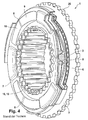
- FIG. 6 shows a plan view of a mounted as an assembly inventive ⁇ en bias unit 1.
- the holding pot 20 has formed a holding member 22 which is rotatably connected to a housing.
- the first one Ramp disc 2 designed as non-rotatable swivel ramp disc.
- at least one linear guide in the direction of the axis 12 of the biasing unit 1 is provided between the first ramp disc 2 and the holding cup 20.
- the linear guide is achieved in that pairs of grooves are formed on the holding pot 20 and the first non-rotatable ramp disc 2, in which a plurality of rolling elements 21 are arranged to reduce the friction in the direction of the axis 12.
- balls are preferred as rolling elements 21.
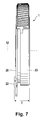
- FIG. 7 shows a side view of a mounted as an assembly bias unit according to the invention 1. It is clearly apparent that the preassembled bias unit 1 has a small overall depth T. Thus, a space-saving installation of the biasing unit 1 in a transmission or the like is possible. Furthermore, this also reduces the weight of the biasing unit 1. All components of the biasing unit 1 according to the invention are arranged around the ash 12 around and form a preassembled unit.
- FIG. 8 shows a perspective view of the exploded view of the bias unit according to the invention 1.
- the bias unit 1 according to this embodiment consists of a first ramp plate 2, a cage 4 and a second ramp disc 5.
- rolling elements 3 referred to as roles.
- three ramp contours 8 are formed in the ramp discs 2 and 5 respectively. It will be understood by those skilled in the art that the number of rolling elements 3 and ramp contours 8 mentioned in the description can not be construed as limiting the invention.
- the cage 4 has therefore three receptacles 4 1 , 4 2 and 4 3 formed for the bearings 3.
- the rolling bearings 3 are formed as rollers.
- the ramp contours 8 can be designed in various ways. Their design is not explicitly mentioned here, since this is not the subject of the invention.
- the ramp contour 8 is at least formed such that the thus formed track 10 is adapted to receive the radial forces of the biasing unit 1. The forces are introduced via the rotary pot 23, which is pivoted to actuate the biasing unit 1 with an actuating segment 37 in a corresponding manner about the axis 12 of the biasing unit 1.
- the first ramp disc 2, the cage 4 and the second ramp disc are used for mounting in the holding pot 20.
- the holding pot 20 itself is inserted into the rotary pot 23.
- a thrust washer 35 is provided between the rotatable-pivotable ramp disc (in the embodiment shown here, this is the second ramp disc 5) and the holding pot 20, a thrust washer 35 is provided.
- an angle plate 36 is provided between the holding pot 20 and the rotary pot 23.
- the holding pot 20 has a radially circumferential wall 27 formed. On the inner side 27a of the radially encircling wall 27 a plurality of raceways 29 are formed.
- the non-rotatably pivotable ramp disc here the first ramp disc 2
- cup-shaped and thus also has a radially encircling wall 31, on the outside 31a raceways 33 are formed.
- the raceways 29 are arranged opposite the raceways 33. It is particularly advantageous if in each case three raceways 29 and 33 are formed and these are each arranged at an angle of 120 °.
- a rolling element 21 is provided in each pair of raceways 29 and 33.
- the rotary pot 23 has formed around the axis 12 arranged cylinder 23 a, on which a plurality of contours 25 are formed. These contours 25 cooperate with corresponding contours 27 of the rotatable pivotable ramp disc (here the second ramp disc 5). Thus, a pivotal movement of the rotary pot 23 is transmitted to a corresponding pivoting movement of the second ramp disc 5.
- the first ramp disc 2 and also the second ramp disc 5 are preferably formed from a sheet metal blank or stamped and stamped part, which are produced by cold forming. With a corresponding forming process and the holding pot and the rotary pot 23 are made.
- FIG. 9 shows a sectional view of the mounted as an assembly bias unit according to the invention 1.
- the rotary pot 23 with the centrally disposed cylinder 23a is configured such that the rotary pot 23 receives all other components of the biasing unit 1 and this holds in the components assigned to the mobility.
- the other components are: the first ramp disc 2, the cage 4 with the rolling elements 3, the second ramp disc 5, the thrust washer 35, the holding pot 20 and the angle disc 36th
- FIG. 10 shows a plan view of the in FIG. 9 X designated cutting surface of the bias unit according to the invention 1.
- FIG. 11 a top view of the in FIG. 9 Shown with Y sectional area of the bias unit 1 according to the invention.
- the cylinder 23a formed on the rotary pot 23 has at its free end 23e a caulking 42, which secures the entire assembly of the pretensioning unit 1.
- it is off FIG. 10 the interaction of the track 29 in the radially encircling wall 27 of the holding pot 20 with the track 33 in the radially encircling wall 31 of the non-rotatable swivel ramp disc (in this embodiment, the first ramp disc 2) to recognize.
- the guided in the raceways 29 and 33 rolling elements allow a linear guide along the axis 12 of the biasing unit 1 and prevent rotation of the second ramp disc 2.
- a linear guide along the axis 12 of the biasing unit 1 allows rotation of the second ramp disc 2.
- the cage 4 supports the cage 4.
- the rolling elements 3 are provided between the first and the second ramp discs 2 and 5 and run on the ramp contours formed in the ramp discs 8.
- FIG. 12 illustrates the principle of operation of the biasing unit 1 according to the invention in the operation of the rotary pot 23.
- the spur gear of an electric motor acts on the actuator 37 of the rotary pot 23 a.
- the result is a direction of movement T act out of the plane of the drawing.
- This movement is transmitted by means of the contours 25 on the cylinder 23 a of the rotary pot 23 to the second ramp disc 5.
- the second ramp disc 5 rotates with respect to the first ramp disc 2 and the rolling elements 3 run on the ramp contours 8 from.
- the first ramp disc 2 is not pivotally rotatable so that it performs a movement in the direction of the axis 12.
- the biasing unit 1 thus exerts a force in F ax in the axial direction.
- the rolling elements 21 roll in the raceways 29 and 31 from.
- FIG. 13 shows a schematic representation of the forces acting in the biasing unit 1 according to the invention forces.
- a force F t acts on the actuating element 37. This force F t is directed out of the plane of the drawing.
- the forces F L which act on the rolling elements 21 in the region of the raceways 29 and 31, cancel each other.
- the forces F tR in the area of the rolling bodies cancel between the first ramp disk 2 and the second ramp disk 5. Due to the stroke between the first ramp disc 2 and the second ramp disc results in a force F NR .
- FIG. 14 shows a schematic plan view of the bias unit 1 according to the invention and the forces acting.
- the pivoting or rotation of the rotary pot 23 is achieved by the action of a force F t on the actuator 37.
- the rolling elements 3 between the first ramp disc 2 and the second ramp disc 5 are seconded in the cage 4 on a circle with the diameter d R.
- the guided between the two raceways 29 and 33 rolling elements 21 are arranged on a circle with the diameter d K , where d K is greater than d R.
- On the rolling elements 21 acts a radial force F tK .
- F tK ⁇ F tR ⁇ ⁇ F NO
Landscapes
- Engineering & Computer Science (AREA)
- General Engineering & Computer Science (AREA)
- Mechanical Engineering (AREA)
- Rolling Contact Bearings (AREA)
Claims (16)
- Unité de précontrainte (1) comprenant un premier disque à rampe (2) et un deuxième disque à rampe (5), dans lesquels sont formés plusieurs contours de rampe (8) dans un côté d'une surface annulaire des disques à rampes (2, 5), de telle sorte que plusieurs corps de roulement (3) soient disposés entre les contours de rampe (8) respectifs du premier disque à rampe (2) et du deuxième disque à rampe (5), de telle sorte que, dans l'unité de précontrainte (1), grâce à un pivotement en rotation de l'un des deux disques rampes (2, 5) par rapport à l'autre disque à rampe (5, 2) non pivotant en rotation autour d'un axe (12), les corps de roulement (3) montent et/ou descendent sur les contours de rampe (8), les corps de roulement (3) étant retenus de manière à roulier dans une cage (4), caractérisée en ce qu' au moins le premier disque à rampe (2), la cage (4) et le deuxième disque à rampe (5) sont placés dans un pot de retenue (20) qui est relié de manière solidaire en rotation à un boîtier à l'aide d'au moins un élément de retenue (22), et en ce que plusieurs corps de roulement (21) sont disposés entre le pot de retenue (20) et le disque à rampe (5, 2) non pivotant en rotation, pour le guidage axial.
- Unité de précontrainte (1) selon la revendication 1, caractérisée en ce qu'au moins le premier disque à rampe (2), la cage (4), le deuxième disque à rampe (5) et le pot de retenue (20) sont insérés dans un pot rotatif (23) qui coopère avec le disque à rampe (5, 2) pivotant en rotation.
- Unité de précontrainte (1) selon la revendication 2, caractérisée en ce que plusieurs contours (25) sont formés dans le pot rotatif (23), lesquels contours coopèrent avec des contours correspondants (27) du disque à rampe (5, 2) pivotant en rotation.
- Unité de précontrainte (1) selon la revendication 3, caractérisée en ce que les contours (25) du pot rotatif (23) présentent une configuration en forme de clavette.
- Unité de précontrainte selon la revendication 1, caractérisée en ce qu'une paroi radialement périphérique (27) est réalisée dans le pot de retenue (20), dans laquelle paroi est réalisé un chemin de roulement (29) pour chacun des corps de roulement (21), et en ce qu'une paroi radialement périphérique (31) est également formée dans le disque à rampe (5, 2) non pivotant en rotation, dans laquelle paroi est également réalisé un chemin de roulement (33) pour chacun des corps de roulement (21), de telle sorte que le disque à rampe (5, 2) non pivotant en rotation et le pot de retenue (20) soient mobiles axialement l'un par rapport à l'autre.
- Unité de précontrainte (1) selon la revendication 5, caractérisée en ce que les chemins de roulement (29) sont disposés de manière uniformément répartie dans la paroi radialement périphérique (27) du pot de retenue (20) et les chemins de roulement (33) sont disposés de manière uniformément répartie dans la paroi radialement périphérique (31) du disque à rampe (5, 2) non pivotant en rotation.
- unité de précontrainte selon la revendication 5, caractérisée en ce que trois chemins de roulement (29, 33) respectifs sont réalisés, dans lesquels est guidé à chaque fois un corps de roulement (21) formé en tant que bille.
- Unité de précontrainte selon la revendication 1, caractérisée en ce qu'un disque de butée (35) est prévu entre le disque à rampe (5, 2) pivotant en rotation et le pot de retenue (20), et en ce qu'un disque coudé (37) est prévu entre le pot de retenue (20) et le pot rotatif (23).
- unité de précontrainte selon la revendication 1, caractérisée en ce qu'un élément d'actionnement (37) est réalisé sur le pot rotatif (23), au moyen duquel élément d'actionnement le pot rotatif (23) peut être pivoté autour de l'axe (12).
- Unité de précontrainte selon la revendication 1, caractérisée en ce que chaque contour de rampe (8) comporte une première rampe (9) et une deuxième rampe (10).
- Unité de précontrainte (1) selon la revendication 1, caractérisée en ce qu'une surface de roulement (40) essentiellement uniforme est formée dans chaque contour de rampe (8), laquelle surface de roulement possède une inclinaison constante par rapport à l'axe (12).
- Unité de précontrainte (1) selon la revendication 1, caractérisée en ce qu'une surface de roulement (40) essentiellement uniforme est formée dans chaque contour de rampe (8), laquelle surface de roulement possède une inclinaison variable par rapport à l'axe (12).
- Unité de précontrainte (1) selon la revendication 11, caractérisée en ce que les surfaces de roulement (10) comprennent un point de contact initial (101) et un point de contact final (102) pour les corps de roulement (3), une butée de fin de course (14) étant formée au point de contact final (102) pour les corps de roulement (3).
- Unité de précontrainte (1) selon la revendication 13, caractérisée en ce que la butée de fin de course (14) est réalisée au point le plus bas du chemin de roulement (10).
- Unité de précontrainte (1) selon la revendication 1, caractérisée en ce que les corps de roulement (3) sont réalisés sous forme de rouleaux entre le premier et le deuxième disque à rampe (2, 5).
- Unité de précontrainte (1) selon la revendication 1, caractérisée en ce que le premier disque à rampe (2), la cage (4), le deuxième disque à rampe (5), le disque de butée (35), le pot de retenue (20), le disque coudé (37) et le pot rotatif (23) de l'unité de précontrainte (1) sont assemblés pour former une unité prémontée.
Applications Claiming Priority (2)
| Application Number | Priority Date | Filing Date | Title |
|---|---|---|---|
| DE102008031512A DE102008031512A1 (de) | 2008-07-03 | 2008-07-03 | Vorspanneinheit |
| PCT/EP2009/058020 WO2010000674A1 (fr) | 2008-07-03 | 2009-06-26 | Unité de précharge |
Publications (2)
| Publication Number | Publication Date |
|---|---|
| EP2297475A1 EP2297475A1 (fr) | 2011-03-23 |
| EP2297475B1 true EP2297475B1 (fr) | 2013-04-17 |
Family
ID=41066207
Family Applications (1)
| Application Number | Title | Priority Date | Filing Date |
|---|---|---|---|
| EP09772374.6A Not-in-force EP2297475B1 (fr) | 2008-07-03 | 2009-06-26 | Unité de précharge |
Country Status (4)
| Country | Link |
|---|---|
| US (1) | US8444523B2 (fr) |
| EP (1) | EP2297475B1 (fr) |
| DE (1) | DE102008031512A1 (fr) |
| WO (1) | WO2010000674A1 (fr) |
Families Citing this family (8)
| Publication number | Priority date | Publication date | Assignee | Title |
|---|---|---|---|---|
| DE102008018846A1 (de) * | 2008-04-15 | 2009-10-22 | Schaeffler Kg | Vorspanneinheit |
| DE102009013121A1 (de) * | 2009-03-13 | 2010-09-16 | Schaeffler Technologies Gmbh & Co. Kg | Geregelte axiale Vorspanneinheit |
| FR2971317A1 (fr) * | 2011-02-08 | 2012-08-10 | Peugeot Citroen Automobiles Sa | Module mecanique compact permettant d'exercer un effort axial dans un ensemble d'elements tournants |
| DE102011083047A1 (de) * | 2011-09-20 | 2013-03-21 | Schaeffler Technologies AG & Co. KG | Axialverstelleinheit |
| DE102014203590A1 (de) * | 2014-02-27 | 2015-08-27 | Schaeffler Technologies AG & Co. KG | Vorspanneinheit |
| WO2019101298A1 (fr) * | 2017-11-21 | 2019-05-31 | Gkn Automotive Ltd. | Procédé de commande d'un actionneur pour moyen d'accouplement |
| CN114402147B (zh) * | 2019-10-03 | 2023-12-15 | 住友电工烧结合金株式会社 | 烧结部件及电磁耦合器 |
| DE102020105178A1 (de) | 2020-02-27 | 2021-09-02 | Schaeffler Technologies AG & Co. KG | Axialverstelleinheit, Kupplungsmodul und Verteilergetriebe |
Family Cites Families (8)
| Publication number | Priority date | Publication date | Assignee | Title |
|---|---|---|---|---|
| US5485904A (en) | 1994-01-31 | 1996-01-23 | Eaton Corporation | Clutch ball ramp actuator with drive and coast apply |
| CA2143065C (fr) | 1994-02-22 | 1999-11-16 | Gregory J. Organek | Mecanisme de verrouillage double action pour actionneur de rampe |
| US5620072A (en) | 1995-02-03 | 1997-04-15 | Borg-Warner Automotive, Inc. | Transfer case having disc pack and cone clutch |
| AU2003228281A1 (en) | 2002-03-08 | 2003-09-22 | Yves J. Kemper | Force compensation and actuator system |
| US7083033B2 (en) | 2003-03-27 | 2006-08-01 | Tochigi Fuji Sangyo Kabushiki Kaisha | Torque transmission apparatus |
| US6935475B2 (en) * | 2003-03-28 | 2005-08-30 | Borgwarner, Inc. | Electromagnetic clutch having ball ramp actuator and torsion spring |
| DE102005053555B3 (de) | 2005-11-08 | 2007-08-02 | Gkn Driveline International Gmbh | Kugelrampenanordnung mit variabler Steigung der Kugelrillen |
| DE102008018846A1 (de) * | 2008-04-15 | 2009-10-22 | Schaeffler Kg | Vorspanneinheit |
-
2008
- 2008-07-03 DE DE102008031512A patent/DE102008031512A1/de not_active Withdrawn
-
2009
- 2009-06-26 EP EP09772374.6A patent/EP2297475B1/fr not_active Not-in-force
- 2009-06-26 WO PCT/EP2009/058020 patent/WO2010000674A1/fr not_active Ceased
- 2009-06-26 US US13/000,875 patent/US8444523B2/en not_active Expired - Fee Related
Also Published As
| Publication number | Publication date |
|---|---|
| DE102008031512A1 (de) | 2010-01-07 |
| WO2010000674A1 (fr) | 2010-01-07 |
| US8444523B2 (en) | 2013-05-21 |
| EP2297475A1 (fr) | 2011-03-23 |
| US20110100780A1 (en) | 2011-05-05 |
Similar Documents
| Publication | Publication Date | Title |
|---|---|---|
| EP2217823B1 (fr) | Module à unité de précontrainte | |
| EP2153080B1 (fr) | Dispositif d'embrayage double avec element de guidage de piston | |
| EP2297475A1 (fr) | Unité de précharge | |
| EP3488117B1 (fr) | Ensemble actionneur et ensemble embrayage | |
| AT503360A2 (de) | Getriebeanordnung zur variablen drehmomentverteilung | |
| DE112009002345T5 (de) | Verarbeitung von Videodaten in Geräten mit eingeschränkten Ressourcen | |
| DE102008011914B4 (de) | Vorspanneinheit | |
| DE102008018846A1 (de) | Vorspanneinheit | |
| EP2406515B1 (fr) | Unite de precontrainte axiale a reglage | |
| DE102009021873B4 (de) | Vorspanneinheit | |
| DE69611900T2 (de) | Differentialgetriebe und Methode zur Herstellung der dafür verwendeten Nockenscheiben | |
| DE102018124444B4 (de) | Rampenaktuator und Schrägkugellagereinheit mit kaltumgeformtem Außenring und geprägter Rampenkontur sowie Verfahren zum Herstellen einer Rampenscheibe | |
| DE19952124A1 (de) | Kupplungsausrückhebel mit Rollen | |
| DE102013215849A1 (de) | Antriebswandlervorrichtung und Achsgetriebevorrichtung mit einer Antriebswandlervorrichtung | |
| DE102008031542A1 (de) | Trockendoppelkupplung für ein Getriebe | |
| DE102009021874A1 (de) | Vorspanneinheit | |
| DE102014203590A1 (de) | Vorspanneinheit | |
| DE102023122917A1 (de) | Aktuatoranordnung für eine Reiblamellenkupplung und Differentialanordnung mit einer solchen Aktuatoranordnung | |
| DE202006020107U1 (de) | Antriebsanordnung mit Toleranzring | |
| EP2270362A1 (fr) | Unité de pré-tension | |
| EP3642508A1 (fr) | Embrayage centrifuge avec masses centrifuges fabriquées sans enlèvement de copeaux | |
| DE102021207659B4 (de) | Stirnraddifferential mit passiver Sperrfunktion sowie Antriebsstrang und Kraftfahrzeug mit einem solchen Differential | |
| DE102009054878A1 (de) | Axialverstelleinrichtung, beispielsweise für eine Kupplung eines Kraftfahrzeuges | |
| DE102024205704A1 (de) | Differenzialsperreinrichtung sowie Differenzialgetriebe | |
| WO2025195560A1 (fr) | Unité de limitation d'angle de rotation pour un système de direction d'un véhicule |
Legal Events
| Date | Code | Title | Description |
|---|---|---|---|
| PUAI | Public reference made under article 153(3) epc to a published international application that has entered the european phase |
Free format text: ORIGINAL CODE: 0009012 |
|
| 17P | Request for examination filed |
Effective date: 20110203 |
|
| AK | Designated contracting states |
Kind code of ref document: A1 Designated state(s): AT BE BG CH CY CZ DE DK EE ES FI FR GB GR HR HU IE IS IT LI LT LU LV MC MK MT NL NO PL PT RO SE SI SK TR |
|
| AX | Request for extension of the european patent |
Extension state: AL BA RS |
|
| DAX | Request for extension of the european patent (deleted) | ||
| RAP1 | Party data changed (applicant data changed or rights of an application transferred) |
Owner name: SCHAEFFLER TECHNOLOGIES AG & CO. KG |
|
| GRAP | Despatch of communication of intention to grant a patent |
Free format text: ORIGINAL CODE: EPIDOSNIGR1 |
|
| GRAS | Grant fee paid |
Free format text: ORIGINAL CODE: EPIDOSNIGR3 |
|
| GRAA | (expected) grant |
Free format text: ORIGINAL CODE: 0009210 |
|
| AK | Designated contracting states |
Kind code of ref document: B1 Designated state(s): AT BE BG CH CY CZ DE DK EE ES FI FR GB GR HR HU IE IS IT LI LT LU LV MC MK MT NL NO PL PT RO SE SI SK TR |
|
| REG | Reference to a national code |
Ref country code: GB Ref legal event code: FG4D Free format text: NOT ENGLISH |
|
| REG | Reference to a national code |
Ref country code: CH Ref legal event code: EP |
|
| REG | Reference to a national code |
Ref country code: IE Ref legal event code: FG4D Free format text: LANGUAGE OF EP DOCUMENT: GERMAN |
|
| REG | Reference to a national code |
Ref country code: AT Ref legal event code: REF Ref document number: 607489 Country of ref document: AT Kind code of ref document: T Effective date: 20130515 |
|
| REG | Reference to a national code |
Ref country code: DE Ref legal event code: R096 Ref document number: 502009006894 Country of ref document: DE Effective date: 20130613 |
|
| REG | Reference to a national code |
Ref country code: LT Ref legal event code: MG4D |
|
| REG | Reference to a national code |
Ref country code: NL Ref legal event code: VDEP Effective date: 20130417 |
|
| PG25 | Lapsed in a contracting state [announced via postgrant information from national office to epo] |
Ref country code: FI Free format text: LAPSE BECAUSE OF FAILURE TO SUBMIT A TRANSLATION OF THE DESCRIPTION OR TO PAY THE FEE WITHIN THE PRESCRIBED TIME-LIMIT Effective date: 20130417 Ref country code: SE Free format text: LAPSE BECAUSE OF FAILURE TO SUBMIT A TRANSLATION OF THE DESCRIPTION OR TO PAY THE FEE WITHIN THE PRESCRIBED TIME-LIMIT Effective date: 20130417 Ref country code: NO Free format text: LAPSE BECAUSE OF FAILURE TO SUBMIT A TRANSLATION OF THE DESCRIPTION OR TO PAY THE FEE WITHIN THE PRESCRIBED TIME-LIMIT Effective date: 20130717 Ref country code: PT Free format text: LAPSE BECAUSE OF FAILURE TO SUBMIT A TRANSLATION OF THE DESCRIPTION OR TO PAY THE FEE WITHIN THE PRESCRIBED TIME-LIMIT Effective date: 20130819 Ref country code: LT Free format text: LAPSE BECAUSE OF FAILURE TO SUBMIT A TRANSLATION OF THE DESCRIPTION OR TO PAY THE FEE WITHIN THE PRESCRIBED TIME-LIMIT Effective date: 20130417 Ref country code: GR Free format text: LAPSE BECAUSE OF FAILURE TO SUBMIT A TRANSLATION OF THE DESCRIPTION OR TO PAY THE FEE WITHIN THE PRESCRIBED TIME-LIMIT Effective date: 20130718 Ref country code: SI Free format text: LAPSE BECAUSE OF FAILURE TO SUBMIT A TRANSLATION OF THE DESCRIPTION OR TO PAY THE FEE WITHIN THE PRESCRIBED TIME-LIMIT Effective date: 20130417 Ref country code: IS Free format text: LAPSE BECAUSE OF FAILURE TO SUBMIT A TRANSLATION OF THE DESCRIPTION OR TO PAY THE FEE WITHIN THE PRESCRIBED TIME-LIMIT Effective date: 20130817 Ref country code: ES Free format text: LAPSE BECAUSE OF FAILURE TO SUBMIT A TRANSLATION OF THE DESCRIPTION OR TO PAY THE FEE WITHIN THE PRESCRIBED TIME-LIMIT Effective date: 20130728 |
|
| PG25 | Lapsed in a contracting state [announced via postgrant information from national office to epo] |
Ref country code: LV Free format text: LAPSE BECAUSE OF FAILURE TO SUBMIT A TRANSLATION OF THE DESCRIPTION OR TO PAY THE FEE WITHIN THE PRESCRIBED TIME-LIMIT Effective date: 20130417 Ref country code: PL Free format text: LAPSE BECAUSE OF FAILURE TO SUBMIT A TRANSLATION OF THE DESCRIPTION OR TO PAY THE FEE WITHIN THE PRESCRIBED TIME-LIMIT Effective date: 20130417 Ref country code: BG Free format text: LAPSE BECAUSE OF FAILURE TO SUBMIT A TRANSLATION OF THE DESCRIPTION OR TO PAY THE FEE WITHIN THE PRESCRIBED TIME-LIMIT Effective date: 20130717 Ref country code: CY Free format text: LAPSE BECAUSE OF FAILURE TO SUBMIT A TRANSLATION OF THE DESCRIPTION OR TO PAY THE FEE WITHIN THE PRESCRIBED TIME-LIMIT Effective date: 20130417 Ref country code: HR Free format text: LAPSE BECAUSE OF FAILURE TO SUBMIT A TRANSLATION OF THE DESCRIPTION OR TO PAY THE FEE WITHIN THE PRESCRIBED TIME-LIMIT Effective date: 20130417 |
|
| BERE | Be: lapsed |
Owner name: SCHAEFFLER TECHNOLOGIES A.G. & CO. KG Effective date: 20130630 |
|
| REG | Reference to a national code |
Ref country code: DE Ref legal event code: R097 Ref document number: 502009006894 Country of ref document: DE |
|
| PG25 | Lapsed in a contracting state [announced via postgrant information from national office to epo] |
Ref country code: MC Free format text: LAPSE BECAUSE OF FAILURE TO SUBMIT A TRANSLATION OF THE DESCRIPTION OR TO PAY THE FEE WITHIN THE PRESCRIBED TIME-LIMIT Effective date: 20130417 Ref country code: SK Free format text: LAPSE BECAUSE OF FAILURE TO SUBMIT A TRANSLATION OF THE DESCRIPTION OR TO PAY THE FEE WITHIN THE PRESCRIBED TIME-LIMIT Effective date: 20130417 Ref country code: DK Free format text: LAPSE BECAUSE OF FAILURE TO SUBMIT A TRANSLATION OF THE DESCRIPTION OR TO PAY THE FEE WITHIN THE PRESCRIBED TIME-LIMIT Effective date: 20130417 Ref country code: CZ Free format text: LAPSE BECAUSE OF FAILURE TO SUBMIT A TRANSLATION OF THE DESCRIPTION OR TO PAY THE FEE WITHIN THE PRESCRIBED TIME-LIMIT Effective date: 20130417 Ref country code: EE Free format text: LAPSE BECAUSE OF FAILURE TO SUBMIT A TRANSLATION OF THE DESCRIPTION OR TO PAY THE FEE WITHIN THE PRESCRIBED TIME-LIMIT Effective date: 20130417 |
|
| REG | Reference to a national code |
Ref country code: CH Ref legal event code: PL |
|
| PLBE | No opposition filed within time limit |
Free format text: ORIGINAL CODE: 0009261 |
|
| STAA | Information on the status of an ep patent application or granted ep patent |
Free format text: STATUS: NO OPPOSITION FILED WITHIN TIME LIMIT |
|
| PG25 | Lapsed in a contracting state [announced via postgrant information from national office to epo] |
Ref country code: RO Free format text: LAPSE BECAUSE OF FAILURE TO SUBMIT A TRANSLATION OF THE DESCRIPTION OR TO PAY THE FEE WITHIN THE PRESCRIBED TIME-LIMIT Effective date: 20130417 Ref country code: IT Free format text: LAPSE BECAUSE OF FAILURE TO SUBMIT A TRANSLATION OF THE DESCRIPTION OR TO PAY THE FEE WITHIN THE PRESCRIBED TIME-LIMIT Effective date: 20130417 Ref country code: NL Free format text: LAPSE BECAUSE OF FAILURE TO SUBMIT A TRANSLATION OF THE DESCRIPTION OR TO PAY THE FEE WITHIN THE PRESCRIBED TIME-LIMIT Effective date: 20130417 |
|
| RAP2 | Party data changed (patent owner data changed or rights of a patent transferred) |
Owner name: SCHAEFFLER TECHNOLOGIES GMBH & CO. KG |
|
| 26N | No opposition filed |
Effective date: 20140120 |
|
| GBPC | Gb: european patent ceased through non-payment of renewal fee |
Effective date: 20130717 |
|
| REG | Reference to a national code |
Ref country code: IE Ref legal event code: MM4A |
|
| REG | Reference to a national code |
Ref country code: DE Ref legal event code: R081 Ref document number: 502009006894 Country of ref document: DE Owner name: SCHAEFFLER TECHNOLOGIES GMBH & CO. KG, DE Free format text: FORMER OWNER: SCHAEFFLER TECHNOLOGIES AG & CO. KG, 91074 HERZOGENAURACH, DE Effective date: 20140213 Ref country code: DE Ref legal event code: R081 Ref document number: 502009006894 Country of ref document: DE Owner name: SCHAEFFLER TECHNOLOGIES AG CO. KG, DE Free format text: FORMER OWNER: SCHAEFFLER TECHNOLOGIES AG CO. KG, 91074 HERZOGENAURACH, DE Effective date: 20140213 Ref country code: DE Ref legal event code: R081 Ref document number: 502009006894 Country of ref document: DE Owner name: SCHAEFFLER TECHNOLOGIES AG & CO. KG, DE Free format text: FORMER OWNER: SCHAEFFLER TECHNOLOGIES AG & CO. KG, 91074 HERZOGENAURACH, DE Effective date: 20140213 |
|
| REG | Reference to a national code |
Ref country code: FR Ref legal event code: ST Effective date: 20140228 |
|
| PG25 | Lapsed in a contracting state [announced via postgrant information from national office to epo] |
Ref country code: BE Free format text: LAPSE BECAUSE OF NON-PAYMENT OF DUE FEES Effective date: 20130630 |
|
| PG25 | Lapsed in a contracting state [announced via postgrant information from national office to epo] |
Ref country code: LI Free format text: LAPSE BECAUSE OF NON-PAYMENT OF DUE FEES Effective date: 20130630 Ref country code: CH Free format text: LAPSE BECAUSE OF NON-PAYMENT OF DUE FEES Effective date: 20130630 Ref country code: IE Free format text: LAPSE BECAUSE OF NON-PAYMENT OF DUE FEES Effective date: 20130626 Ref country code: GB Free format text: LAPSE BECAUSE OF NON-PAYMENT OF DUE FEES Effective date: 20130717 |
|
| REG | Reference to a national code |
Ref country code: DE Ref legal event code: R097 Ref document number: 502009006894 Country of ref document: DE Effective date: 20140120 |
|
| PG25 | Lapsed in a contracting state [announced via postgrant information from national office to epo] |
Ref country code: FR Free format text: LAPSE BECAUSE OF NON-PAYMENT OF DUE FEES Effective date: 20130701 |
|
| PG25 | Lapsed in a contracting state [announced via postgrant information from national office to epo] |
Ref country code: MT Free format text: LAPSE BECAUSE OF FAILURE TO SUBMIT A TRANSLATION OF THE DESCRIPTION OR TO PAY THE FEE WITHIN THE PRESCRIBED TIME-LIMIT Effective date: 20130417 |
|
| REG | Reference to a national code |
Ref country code: DE Ref legal event code: R081 Ref document number: 502009006894 Country of ref document: DE Owner name: SCHAEFFLER TECHNOLOGIES AG & CO. KG, DE Free format text: FORMER OWNER: SCHAEFFLER TECHNOLOGIES GMBH & CO. KG, 91074 HERZOGENAURACH, DE Effective date: 20150126 |
|
| PG25 | Lapsed in a contracting state [announced via postgrant information from national office to epo] |
Ref country code: TR Free format text: LAPSE BECAUSE OF FAILURE TO SUBMIT A TRANSLATION OF THE DESCRIPTION OR TO PAY THE FEE WITHIN THE PRESCRIBED TIME-LIMIT Effective date: 20130417 |
|
| REG | Reference to a national code |
Ref country code: AT Ref legal event code: PC Ref document number: 607489 Country of ref document: AT Kind code of ref document: T Owner name: SCHAEFFLER TECHNOLOGIES AG & CO. KG, DE Effective date: 20150526 |
|
| PG25 | Lapsed in a contracting state [announced via postgrant information from national office to epo] |
Ref country code: MK Free format text: LAPSE BECAUSE OF FAILURE TO SUBMIT A TRANSLATION OF THE DESCRIPTION OR TO PAY THE FEE WITHIN THE PRESCRIBED TIME-LIMIT Effective date: 20130417 Ref country code: LU Free format text: LAPSE BECAUSE OF NON-PAYMENT OF DUE FEES Effective date: 20130626 Ref country code: HU Free format text: LAPSE BECAUSE OF FAILURE TO SUBMIT A TRANSLATION OF THE DESCRIPTION OR TO PAY THE FEE WITHIN THE PRESCRIBED TIME-LIMIT; INVALID AB INITIO Effective date: 20090626 |
|
| PGFP | Annual fee paid to national office [announced via postgrant information from national office to epo] |
Ref country code: AT Payment date: 20180702 Year of fee payment: 10 |
|
| PGFP | Annual fee paid to national office [announced via postgrant information from national office to epo] |
Ref country code: DE Payment date: 20180831 Year of fee payment: 10 |
|
| REG | Reference to a national code |
Ref country code: DE Ref legal event code: R119 Ref document number: 502009006894 Country of ref document: DE |
|
| REG | Reference to a national code |
Ref country code: AT Ref legal event code: MM01 Ref document number: 607489 Country of ref document: AT Kind code of ref document: T Effective date: 20190626 |
|
| PG25 | Lapsed in a contracting state [announced via postgrant information from national office to epo] |
Ref country code: AT Free format text: LAPSE BECAUSE OF NON-PAYMENT OF DUE FEES Effective date: 20190626 Ref country code: DE Free format text: LAPSE BECAUSE OF NON-PAYMENT OF DUE FEES Effective date: 20200101 |
|
| P01 | Opt-out of the competence of the unified patent court (upc) registered |
Effective date: 20230523 |