EP2297534B1 - Appareil ménager, en particulier appareil frigorifique, et son procédé de production - Google Patents
Appareil ménager, en particulier appareil frigorifique, et son procédé de production Download PDFInfo
- Publication number
- EP2297534B1 EP2297534B1 EP09757483.4A EP09757483A EP2297534B1 EP 2297534 B1 EP2297534 B1 EP 2297534B1 EP 09757483 A EP09757483 A EP 09757483A EP 2297534 B1 EP2297534 B1 EP 2297534B1
- Authority
- EP
- European Patent Office
- Prior art keywords
- wall
- vacuum insulation
- insulation panel
- mould
- appliance
- Prior art date
- Legal status (The legal status is an assumption and is not a legal conclusion. Google has not performed a legal analysis and makes no representation as to the accuracy of the status listed.)
- Active
Links
Images

Classifications
-
- F—MECHANICAL ENGINEERING; LIGHTING; HEATING; WEAPONS; BLASTING
- F25—REFRIGERATION OR COOLING; COMBINED HEATING AND REFRIGERATION SYSTEMS; HEAT PUMP SYSTEMS; MANUFACTURE OR STORAGE OF ICE; LIQUEFACTION SOLIDIFICATION OF GASES
- F25D—REFRIGERATORS; COLD ROOMS; ICE-BOXES; COOLING OR FREEZING APPARATUS NOT OTHERWISE PROVIDED FOR
- F25D23/00—General constructional features
- F25D23/06—Walls
- F25D23/065—Details
-
- F—MECHANICAL ENGINEERING; LIGHTING; HEATING; WEAPONS; BLASTING
- F25—REFRIGERATION OR COOLING; COMBINED HEATING AND REFRIGERATION SYSTEMS; HEAT PUMP SYSTEMS; MANUFACTURE OR STORAGE OF ICE; LIQUEFACTION SOLIDIFICATION OF GASES
- F25D—REFRIGERATORS; COLD ROOMS; ICE-BOXES; COOLING OR FREEZING APPARATUS NOT OTHERWISE PROVIDED FOR
- F25D2201/00—Insulation
- F25D2201/10—Insulation with respect to heat
- F25D2201/14—Insulation with respect to heat using subatmospheric pressure
-
- Y—GENERAL TAGGING OF NEW TECHNOLOGICAL DEVELOPMENTS; GENERAL TAGGING OF CROSS-SECTIONAL TECHNOLOGIES SPANNING OVER SEVERAL SECTIONS OF THE IPC; TECHNICAL SUBJECTS COVERED BY FORMER USPC CROSS-REFERENCE ART COLLECTIONS [XRACs] AND DIGESTS
- Y02—TECHNOLOGIES OR APPLICATIONS FOR MITIGATION OR ADAPTATION AGAINST CLIMATE CHANGE
- Y02B—CLIMATE CHANGE MITIGATION TECHNOLOGIES RELATED TO BUILDINGS, e.g. HOUSING, HOUSE APPLIANCES OR RELATED END-USER APPLICATIONS
- Y02B40/00—Technologies aiming at improving the efficiency of home appliances, e.g. induction cooking or efficient technologies for refrigerators, freezers or dish washers
Definitions
- the present invention relates to a household appliance, in particular a refrigeration appliance, having a body with an inner container and outer walls of the appliance, and an insulation layer located therebetween with at least one embedded vacuum insulation panel.
- a fixed vacuum insulation panel and a refrigeration cabinet element containing this fixed vacuum insulation panel are known.
- the arrangement there consists of a rigid plate and a vacuum insulation panel, the vacuum insulation panel being fixed on the rigid plate by a polyurethane foam applied as a liquid reaction mixture.
- a vacuum insulation panel is centered in a steel cassette, which is provided with a folded edge.
- a circumferential gap between the steel cassette and the vacuum insulation panel is filled with one-component polyurethane foam.
- a polyurethane reaction mixture is applied to the sheet metal side on which the tubes are welded.
- the vacuum insulation panel is placed on the ascending reaction mixture. After the foam has hardened, the plate covered with the aluminum tubes has firmly connected to the vacuum insulation panel.
- a refrigeration device which has an outer device wall and a vacuum insulation panel, the vacuum insulation panel being fastened to an inner side of the outer device wall by means of a liquid adhesive layer.
- the object of the invention is to be able to produce generic household appliances, in particular refrigeration appliances, in high quality at low cost.
- the object is achieved by a household appliance, in particular a refrigerator, with the features of claim 1.
- the invention preferably relates to refrigeration appliances, but it can also be used in other household appliances, such as, for example, air conditioners, which use vacuum insulation panels.
- Vacuum insulation panels are thermal insulation panels that have reduced thermal conductivity due to the evacuation of a body cavity.
- vacuum insulation panels comprise a casing that has a high level of tightness against gas penetration.
- the shell is filled with porous core material.
- the core material forms a solid support body.
- an open-pore core material is usually used, from which the contained gases can be evacuated as completely as possible.
- the high heat-insulating effect of the vacuum insulation panels is mainly achieved by evacuation.
- the support body of a vacuum insulation board should have the lowest possible solid body and radiant heat conductivity.
- different types of material are suitable as support bodies for the production of vacuum insulation boards.
- microporous silicas in particular pyrogenic silicas and perlites, but also micro / cellulose fiber materials or open-cell plastic foams can be used.
- Another requirement for the material for the support body and in particular for its dimensional stability is the pressure resistance. With increasing evacuation, the pressure load from the outside on the envelope of the vacuum insulation panel increases because of the ambient air pressure. The support body material should be able to withstand this pressure load.
- the heat insulation resistance depends essentially on the gas and water vapor barrier ability of the casing. Gas or water vapor that diffuses through the sheath reduces the vacuum in the vacuum insulation panel, thereby losing the heat-insulating effect.
- Aluminum composite foils are therefore usually used as a cover.
- the aluminum layer essentially serves to reflect heat radiation.
- the gas and water vapor barrier ability is predominantly achieved by plastic layers.
- the plastic layers should also have a very high material strength so that mechanical damage does not occur, which would result in air penetrating into the interior of the vacuum insulation panel and thereby lose the heat-insulating effect in this ventilated state would go.
- vacuum insulation panels are produced in a preferably rectangular plate shape.
- the cover sometimes does not lie against the support body in a completely even manner, so that folds of the cover can form. As a result, this leads to uneven vacuum insulation panels.
- unevenness of the support body formed by the evacuation can occur, in particular in the case of bulk material-like core materials. This also leads to uneven vacuum insulation panels.
- the problem with an unevenness of the vacuum insulation panel is that, in the course of the production-related fastening of the vacuum insulation panel to the inside of a device outer wall, the unevenness of the vacuum insulation panel can be seen on the visible outside of the device outer wall or because of the unevenness of the vacuum insulation panel, stresses occur in the device outer wall, which is what leads to an uneven and especially wavy appearance of the outer wall of the device.
- the refrigeration device In order to increase the quality of the refrigeration device, not only should it be ensured that the appearance of the outer wall of the device is optically flawless, but the refrigeration device should also be inexpensive to manufacture and then also be energy-efficient to operate.
- an additional sheet inserted between the vacuum insulation panel and the outer wall of the device can improve the visual appearance, but inserting an additional sheet increases the manufacturing costs and the weight of the finished refrigeration device.
- the outer wall of the device is made significantly thicker instead of an additional sheet.
- the Liquid adhesive layer introduced between the vacuum insulation panel and the inside of the outer wall of the device is not only adhesively bonded to the vacuum insulation panel with the outer wall of the device or the inner container, but at the same time an intermediate layer is created which compensates for unevenness, such as that caused by folds in the envelope of the vacuum insulation panel or by molding on the inner container, e.g. through Rib fields are specified.
- unevenness can arise not only from folds in the casing, but also, for example, when two or more rigid support body components are evacuated in a common casing. Inaccuracies in the position of two support body components relative to one another can lead to step-like edges in the surface of the vacuum insulation panel, which are shown on the outside of the casing after the evacuation.
- the liquid adhesive layer can have a minimum thickness of 3 millimeters (mm). With a minimum thickness of 3 mm, all unevenness and position inaccuracies that occur can be compensated for, at least on the outer wall of the device. A thickness of the foam layer of more than 3 mm can also be realized and is then suitable for compensating for the unevenness on the inner container. Because of the increasing thickness, more foam material is required and the reaction time increases. There should only be a slight deviation from a thickness of 3mm upwards. An increasing response time also means an extended manufacturing time, which in turn leads to higher manufacturing costs. A thickness between 3 and 4 mm can therefore make economic sense.
- Curable liquid adhesives are to be understood as meaning substances and mixtures of substances which, after their reaction with atmospheric oxygen or another reaction component, solidify from their liquid, doughy state at least to a tough-elastic state, but preferably hard state.
- the liquid adhesive layer is in the form of a foamable heat insulation layer.
- the liquid adhesive layer can preferably extend over the entire area between the vacuum insulation panel and the inside of the outside wall of the device. A full-surface extension of the liquid adhesive layer ensures that the entire surface with which the vacuum insulation panel rests on the outer wall of the device remains free of air pockets. Due to the full-surface connection by means of the liquid adhesive layer, there are thermal bridges between the vacuum insulation panel and the outer wall of the device prevented and guaranteed a maximum possible heat insulation effect.
- the liquid adhesive layer extends over the entire surface of a front side of the vacuum insulation panel facing the inside of the device outer wall and its side walls.
- the casings of vacuum insulation panels are usually formed from pocket-like composite films. After the porous core material, whether pourable or as a solid-state component, has been introduced into the pocket, the envelope is closed on its open side in a gas and water vapor tight manner after evacuation.
- the pocket-like casing is usually closed by sealing along an edge section of the pocket-like casing.
- the sealed casing then has a seam-like sealing section which either projects from the casing by a few millimeters to one centimeter or is applied to the casing body by folding over or folding the seam-like sealing section.
- the seam-like sealing section is applied to a side wall of the vacuum insulation panel.
- folds or even undercut hollow chambers also occur on the side walls of the vacuum insulation panel between the folded sealing seam and the vacuum insulation panel body. Air pockets could remain there, which form a thermal bridge and impair the thermal insulation ability.
- the foam layer extends over the entire area not only over a front side of the vacuum insulation panel facing the inside of the device outer wall, but also its side walls, air pockets can also be prevented on the side walls.
- the pre-foaming according to the invention also pre-foams the side walls of the vacuum insulation panel, thereby creating a uniform air layer free of air pockets.
- the invention provides for the vacuum insulation panels to be foamed onto the inside of the outer walls of the appliance in a pre-foaming process upstream of the main foaming process for producing a heat-insulated household appliance.
- Attaching the vacuum insulation panels to the inside of the outside walls of the device results in material and cost savings, since additional stiffening plates or thicker outside walls of the device can be dispensed with.
- the liquid adhesive layer according to the invention between the vacuum insulation panel and the outer wall of the device results in a lower weight for the household appliance than when using additional stiffening plates or thicker outer walls of the device.
- the liquid adhesive layer compensates for unevenness between the vacuum insulation panel and the outside wall of the device. This means that even very uneven vacuum insulation panels can be processed with less expensive ones. Preventing air pockets increases the energy efficiency of the household appliance.
- the foamable heat insulation material layer or a foam system can preferably be formed by a polyurethane foam layer.
- Polyurethane foam layers are generally formed on the basis of polyols with the addition of polyisocyanates, in particular methylene-diphenylene-di-isocyanate (MDI), which mixture is foamed by a blowing agent, in particular pentane, alternatively also methylene chloride or carbon dioxide.
- MDI methylene-diphenylene-di-isocyanate
- Most polyols and polyisocyanates react with each other only at a moderate rate at room temperature. The same applies to the reaction of polyisocyanate with water. Therefore activators, ie accelerators, are added to the reaction mixture.
- a slowly driving foam system is used for the pre-foaming according to the invention. Compared to a normally driving foam system that has a thread time of approx. 35 seconds, a foam system that drives slowly according to the invention can have a thread time of approx.
- the thread time is understood to mean a setting time of the reaction mixture, namely the time from the start of the reaction until threads can be pulled out of the mixture. With this common method, the setting time can be determined very precisely and easily.
- the foam system can be processed with increased density. As a result, foam thicknesses in particular less than 3 mm can be achieved.
- the invention also relates to an associated method for producing a composite body and a prefoaming mold for carrying out the method.
- the method for producing a composite body comprising a vacuum insulation panel and a device outer wall of a refrigeration device, had the steps of inserting the device outer wall into a pre-expansion mold; Applying a mold frame to an inside of the outside wall of the device; Applying a liquid reaction mixture to the inside of the device outer wall bounded by the mold frame; Inserting the vacuum insulation panel into the liquid reaction mixture to form the heat insulation material layer; Closing the pre-expansion mold by placing a cover plate on the mold frame; Keep the pre-expansion mold closed until the liquid reaction mixture has been distributed and cured over the entire area along a front side of the vacuum insulation panel and its side walls facing the inside of the device outer wall.
- the pre-foaming mold can have a bottom for placing an outer wall of the device, a cover plate for closing the pre-foaming mold and a mold frame arranged between the bottom and the top plate.
- a receptacle cavity can be created between the base and the cover plate from the outside adjacent to the mold frame, in particular on two opposite outer sides of the mold frame.
- the receiving cavity or the receiving cavities serve to be able to receive folded-over folded edges of the outer wall of the device in the pre-expansion form.
- a left outer wall of the device and a right outer wall of the device are designed differently, in particular in a mirror image, so that, for example, a folded edge on the front is formed on the left and once on the right on the outer wall of the device.
- the pre-foaming mold has the receiving cavities according to the invention.
- the pre-foaming mold can be designed for releasably inserting mold frames of different sizes.
- the form frame gives the lateral boundaries between the foamed foam layer before.
- the lateral boundaries of the between the foamed foam layer result from the dimensions of the vacuum insulation panel plus the layer thickness of the foam layer, such as 2 by 3 millimeters, that is an excess of a total of 6 millimeters.
- the pre-foaming mold can be designed for inserting intermediate bars which reduce the effective size of the mold frame. This is useful if the size required to foam around the vacuum insulation panel is smaller than the overall size of the mold frame. By inserting intermediate bars according to the invention, additional smaller mold frames are unnecessary.
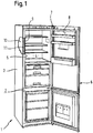
- a refrigerator 1 for household purposes has a cabinet-shaped body 2, the device outer wall 3 delimit an interior 4 of the refrigerator 1.
- a front opening 5 of the body 2 can be closed by means of a door 6.
- the door 6 is pivotally mounted on the body 2 via hinge arrangements 7 about a vertical axis.
- the door 6 has an inner side 8 facing the interior 4 in the closed position.
- an insulation layer 11 is foamed in for heat insulation purposes.
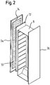
- FIG. 2 shows the inner container 9 with two opposite side device outer walls 3a and 3b, and an example between the in Fig. 2 Device outer wall 3a shown on the left and vacuum insulation panel 12 arranged on the inner container 9.
- the vacuum insulation panel 12 is foamed by means of a foam layer 13 on an inside 14 of the device outer wall 3a.
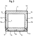
- a first device outer wall 3a can be covered by an in Fig. 3 Appliance outer wall 3 shown on the left are formed. Accordingly, a second outer wall 3b of the device can be covered by an in Fig. 3 Appliance outer wall 3 shown on the right are formed.
- a third outer wall 3c of the device can also be formed, for example, by the door 6 of the refrigeration device 1.
- the insulation layer 11 is foamed between the inner container 9 and the device outer walls 3a and 3b.
- a first vacuum insulation panel 12a is assigned to the first device outer wall 3a. The first vacuum insulation panel 12a is arranged in the region of the inside 14a of the device outer wall 3a.
- the vacuum insulation panel 12a is foamed onto the inside 14a of the first device outer wall 3a by means of a first foam layer 13a.
- a second vacuum insulation panel 12b is assigned to the second device outer wall 3b.
- the second vacuum insulation panel 12b is arranged in the area of the inside 14b of the device outer wall 3b.
- the vacuum insulation panel 12b is foamed onto the inside 14b of the second device outer wall 3b by means of a second foam layer 13b.
- a third device outer wall 3c is formed on the door 6.
- a third vacuum insulation panel 12c is assigned to this third device outer wall 3c on the door side.
- the third vacuum insulation panel 12c is in the area of the inside 14c of the outside wall of the device 3c arranged.
- the vacuum insulation panel 12c is foamed onto the inside 14c of the third device outer wall 3c by means of a third foam layer 13c.
- FIG. 4a A pre-expansion mold 15 according to the invention is shown.
- the prefoaming mold 15 has a bottom 16.
- the bottom 16 is cuboid with a flat top 17.
- the outer wall 3 of the device is placed on the bottom 16 with its visible outside on the top 17 of the bottom 16.
- a molding frame 18 is then placed on the inside 14 of the outer wall 3 of the device.
- the molding frame 18 can be formed by a preferably rectangular circumferentially closed angle profile.
- the molding frame 18 has larger dimensions than the vacuum insulation panel 12 to be foamed by the thickness of the foam layer 13. After the introduction of the liquid, reactive foam layer 13 and the application of the vacuum insulation panel 12, the pre-foaming mold 15 is closed by a cover plate 19.
- a foam layer 13 with increased density can be produced.
- the foam layer 13 is distributed in the pre-foaming mold 15 along a front side 20a and two opposite side walls 20b and 20c of the vacuum insulation panel 12.
- edges of the outer wall 3 of the device protrude at an angle.
- the receiving cavities 21 have a clear width through which Different dimensioned device outer walls 3 with different bent edges can be used in the same pre-expansion mold 15.
- two different, mirror-image device outer walls 3 can be foamed in the same shape.
- Fig. 4b is a section of the Fig. 4a shown enlarged again.
Landscapes
- Engineering & Computer Science (AREA)
- Chemical & Material Sciences (AREA)
- Combustion & Propulsion (AREA)
- Physics & Mathematics (AREA)
- Mechanical Engineering (AREA)
- Thermal Sciences (AREA)
- General Engineering & Computer Science (AREA)
- Refrigerator Housings (AREA)
Claims (9)
- Appareil électroménager, en particulier appareil frigorifique (1) présentant un bâti (2) comprenant un réservoir intérieur (9) et des cloisons extérieures de l'appareil (3, 3a, 3b, 3c), ainsi qu'une couche isolante (11) située entre celles-ci ayant au moins un panneau d'isolation sous vide intercalé (12, 12a, 12b, 12c), le au moins un panneau d'isolation sous vide (12, 12a, 12b, 12c) étant fixé au moins presque à plat contre le côté intérieur (14) d'une cloison extérieure de l'appareil (3, 3a, 3b, 3c) au moyen d'une couche d'un agent adhésif liquide réalisée séparément par rapport à la couche isolante (11), la couche d'un agent adhésif liquide étant réalisée en tant que couche en matière thermo-isolante (13) moussée, laquelle s'étend sur toute sa surface sur un côté frontal du panneau d'isolation sous vide (12, 12a, 12b, 12c) regardant le côté intérieur (14) de la cloison extérieure de l'appareil (3, 3a, 3b, 3c), et sur les cloisons latérales de celui-ci.
- Appareil électroménager selon la revendication 1, caractérisé en ce que la couche d'un agent adhésif liquide s'étend sur toute la surface entre le panneau d'isolation sous vide (12, 12a, 12b, 12c) et le côté intérieur (14) de la cloison extérieure de l'appareil (3, 3a, 3b, 3c).
- Appareil électroménager selon la revendication 1 ou 2, caractérisé en ce que la couche d'un agent adhésif liquide présente une épaisseur minimale de 3 mm.
- Appareil électroménager selon l'une des revendications 1 à 3, caractérisé en ce que la couche d'un agent adhésif liquide est réalisée sous forme de couche de mousse de polyuréthane.
- Procédé de fabrication d'un appareil électroménager selon la revendication 1, comprenant les étapes suivantes:- placement de la cloison extérieure de l'appareil (3, 3a, 3b, 3c) dans un moule de préfixation (15);- pose d'un encadrement de moule (18) sur un côté intérieur (14) de la cloison extérieure de l'appareil (3, 3a, 3b, 3c);- application d'un mélange réactionnel liquide pour la formation d'une couche d'un agent adhésif liquide à mousser (13) sur le côté intérieur (14) de la cloison extérieure de l'appareil (3, 3a, 3b, 3c) délimité par l'encadrement de moule (18);- placement du panneau d'isolation sous vide (12, 12a, 12b, 12c) dans le mélange réactionnel liquide;- fermeture du moule de préfixation (15) par application d'une plaque de recouvrement (19) sur l'encadrement de moule (18);- enfermement du moule de préfixation (15) jusqu'à ce que le mélange réactionnel liquide se répartisse et se durcisse sur toute la surface le long d'un côté frontal (20a du panneau d'isolation sous vide (12, 12a, 12b, 12c) regardant le côté intérieur (14) de la cloison extérieure de l'appareil (3, 3a, 3b, 3c) et des cloisons latérales (20b, 20c) de celui-ci.
- Procédé selon la revendication 5, caractérisé en ce que le moule de préfixation (15) comprend un fond (16), une plaque de recouvrement (19) et un encadrement de moule (18), une cloison extérieure de l'appareil (3, 3a, 3b, 3c) étant déposée sur le fond (16), le moule de prémoussage (15) étant fermé avec la plaque de recouvrement (19), et l'encadrement de moule (18) étant disposé entre le fond (16) et la plaque de recouvrement (19).
- Procédé selon la revendication 6, caractérisé en ce qu'une cavité de logement (21) est créée entre le fond (16) et la plaque de recouvrement (19) jouxtant de l'extérieur l'encadrement de moule (18), en particulier deux faces extérieures de l'encadrement de moule (18) situées l'une en face de l'autre.
- Procédé selon l'une des revendications 5 à 7, caractérisé en ce que le moule de prémoussage (15) est réalisé de dimension différente pour l'insertion amovible de l'encadrement de moule (18).
- Procédé selon l'une des revendications 5 à 7, caractérisé en ce que le moule de prémoussage (15) est réalisé pour la pose de verrous intermédiaires, lesquels réduisent la dimension fonctionnelle de l'encadrement de moule (18).
Priority Applications (1)
| Application Number | Priority Date | Filing Date | Title |
|---|---|---|---|
| PL09757483T PL2297534T3 (pl) | 2008-06-03 | 2009-05-29 | Urządzenie gospodarstwa domowego, zwłaszcza urządzenie chłodzące i sposób jego wytwarzania |
Applications Claiming Priority (2)
| Application Number | Priority Date | Filing Date | Title |
|---|---|---|---|
| DE102008026528A DE102008026528A1 (de) | 2008-06-03 | 2008-06-03 | Haushaltsgerät, insbesondere Kältegerät, sowie Verfahren zum Herstellen eines Verbundkörpers und Vorschäumform zur Durchführung des Verfahrens |
| PCT/EP2009/056641 WO2009147102A1 (fr) | 2008-06-03 | 2009-05-29 | Appareil ménager, en particulier appareil frigorifique, procédé de production d'un corps composite, et moule de prémoussage pour la mise en oeuvre du procédé |
Publications (2)
| Publication Number | Publication Date |
|---|---|
| EP2297534A1 EP2297534A1 (fr) | 2011-03-23 |
| EP2297534B1 true EP2297534B1 (fr) | 2020-07-22 |
Family
ID=41202452
Family Applications (1)
| Application Number | Title | Priority Date | Filing Date |
|---|---|---|---|
| EP09757483.4A Active EP2297534B1 (fr) | 2008-06-03 | 2009-05-29 | Appareil ménager, en particulier appareil frigorifique, et son procédé de production |
Country Status (5)
| Country | Link |
|---|---|
| EP (1) | EP2297534B1 (fr) |
| CN (1) | CN102057238B (fr) |
| DE (1) | DE102008026528A1 (fr) |
| PL (1) | PL2297534T3 (fr) |
| WO (1) | WO2009147102A1 (fr) |
Families Citing this family (42)
| Publication number | Priority date | Publication date | Assignee | Title |
|---|---|---|---|---|
| DE102009060879B4 (de) | 2009-12-30 | 2018-06-14 | Binder Gmbh | Verfahren zur Herstellung einer Dämmschicht eines Kälteschranks |
| MX341379B (es) * | 2010-09-22 | 2016-08-18 | Basf Se | Reparacion de paneles de aislamiento al vacio en aparatos de refrigeracion. |
| US20120067499A1 (en) * | 2010-09-22 | 2012-03-22 | Basf Se | Fixing of vacuum insulation panels in cooling apparatuses |
| DE102011075388A1 (de) | 2011-05-06 | 2012-11-08 | BSH Bosch und Siemens Hausgeräte GmbH | Kältegerät, insbesondere Haushaltskältegerät |
| DE102011075390A1 (de) * | 2011-05-06 | 2012-11-08 | BSH Bosch und Siemens Hausgeräte GmbH | Kältegerät, insbesondere Haushaltskältegerät |
| DE102011075389A1 (de) | 2011-05-06 | 2012-11-08 | BSH Bosch und Siemens Hausgeräte GmbH | Kältegerät, insbesondere Haushaltskältegerät |
| DE102012001372A1 (de) * | 2012-01-24 | 2013-07-25 | Liebherr-Hausgeräte Ochsenhausen GmbH | Kühl- und/oder Gefriergerät |
| DE102012008159A1 (de) * | 2012-03-26 | 2013-09-26 | Liebherr-Hausgeräte Ochsenhausen GmbH | Kühl- und/oder Gefriergerät |
| US9221210B2 (en) | 2012-04-11 | 2015-12-29 | Whirlpool Corporation | Method to create vacuum insulated cabinets for refrigerators |
| US9140481B2 (en) | 2012-04-02 | 2015-09-22 | Whirlpool Corporation | Folded vacuum insulated structure |
| DE102013210484A1 (de) * | 2013-06-06 | 2014-12-11 | BSH Bosch und Siemens Hausgeräte GmbH | Haushaltskältegerät mit einer mehrschichtig aufgebauten Wand sowie Verfahren zum Herstellen eines mehrschichtigen Aufbaus |
| US9689604B2 (en) | 2014-02-24 | 2017-06-27 | Whirlpool Corporation | Multi-section core vacuum insulation panels with hybrid barrier film envelope |
| US10052819B2 (en) | 2014-02-24 | 2018-08-21 | Whirlpool Corporation | Vacuum packaged 3D vacuum insulated door structure and method therefor using a tooling fixture |
| US9599392B2 (en) | 2014-02-24 | 2017-03-21 | Whirlpool Corporation | Folding approach to create a 3D vacuum insulated door from 2D flat vacuum insulation panels |
| DE202014103892U1 (de) | 2014-08-21 | 2015-11-25 | Rehau Ag + Co. | Verschlussanordnung |
| US9476633B2 (en) | 2015-03-02 | 2016-10-25 | Whirlpool Corporation | 3D vacuum panel and a folding approach to create the 3D vacuum panel from a 2D vacuum panel of non-uniform thickness |
| US10161669B2 (en) | 2015-03-05 | 2018-12-25 | Whirlpool Corporation | Attachment arrangement for vacuum insulated door |
| US9897370B2 (en) | 2015-03-11 | 2018-02-20 | Whirlpool Corporation | Self-contained pantry box system for insertion into an appliance |
| US9441779B1 (en) | 2015-07-01 | 2016-09-13 | Whirlpool Corporation | Split hybrid insulation structure for an appliance |
| US10946562B2 (en) | 2015-10-19 | 2021-03-16 | Basf Se | Sandwich structure including a VIP and method for producing the same |
| US10222116B2 (en) | 2015-12-08 | 2019-03-05 | Whirlpool Corporation | Method and apparatus for forming a vacuum insulated structure for an appliance having a pressing mechanism incorporated within an insulation delivery system |
| US12508751B2 (en) | 2015-12-08 | 2025-12-30 | Whirlpool Corporation | Insulation compaction device and method for forming an insulated structure for an appliance |
| US10422573B2 (en) | 2015-12-08 | 2019-09-24 | Whirlpool Corporation | Insulation structure for an appliance having a uniformly mixed multi-component insulation material, and a method for even distribution of material combinations therein |
| US11052579B2 (en) | 2015-12-08 | 2021-07-06 | Whirlpool Corporation | Method for preparing a densified insulation material for use in appliance insulated structure |
| US10429125B2 (en) | 2015-12-08 | 2019-10-01 | Whirlpool Corporation | Insulation structure for an appliance having a uniformly mixed multi-component insulation material, and a method for even distribution of material combinations therein |
| US10041724B2 (en) | 2015-12-08 | 2018-08-07 | Whirlpool Corporation | Methods for dispensing and compacting insulation materials into a vacuum sealed structure |
| US10422569B2 (en) | 2015-12-21 | 2019-09-24 | Whirlpool Corporation | Vacuum insulated door construction |
| US9840042B2 (en) | 2015-12-22 | 2017-12-12 | Whirlpool Corporation | Adhesively secured vacuum insulated panels for refrigerators |
| US10018406B2 (en) | 2015-12-28 | 2018-07-10 | Whirlpool Corporation | Multi-layer gas barrier materials for vacuum insulated structure |
| US10610985B2 (en) | 2015-12-28 | 2020-04-07 | Whirlpool Corporation | Multilayer barrier materials with PVD or plasma coating for vacuum insulated structure |
| US10807298B2 (en) | 2015-12-29 | 2020-10-20 | Whirlpool Corporation | Molded gas barrier parts for vacuum insulated structure |
| US11247369B2 (en) | 2015-12-30 | 2022-02-15 | Whirlpool Corporation | Method of fabricating 3D vacuum insulated refrigerator structure having core material |
| US10712080B2 (en) | 2016-04-15 | 2020-07-14 | Whirlpool Corporation | Vacuum insulated refrigerator cabinet |
| EP3443284B1 (fr) | 2016-04-15 | 2020-11-18 | Whirlpool Corporation | Structure de réfrigérateur à isolation sous vide, dotée de caractéristiques tridimensionnelles |
| US11320193B2 (en) | 2016-07-26 | 2022-05-03 | Whirlpool Corporation | Vacuum insulated structure trim breaker |
| WO2018034665A1 (fr) | 2016-08-18 | 2018-02-22 | Whirlpool Corporation | Compartiment de machine pour une structure isolée sous vide |
| WO2018101954A1 (fr) | 2016-12-02 | 2018-06-07 | Whirlpool Corporation | Ensemble support de charnière |
| US10907888B2 (en) | 2018-06-25 | 2021-02-02 | Whirlpool Corporation | Hybrid pigmented hot stitched color liner system |
| CN109299054B (zh) * | 2018-09-30 | 2020-09-15 | 维沃移动通信有限公司 | 一种数据统计方法及终端设备 |
| CN109968580A (zh) * | 2019-03-28 | 2019-07-05 | 合肥华凌股份有限公司 | 制冷设备及其生产方法 |
| DE102020204084A1 (de) | 2020-03-30 | 2021-09-30 | BSH Hausgeräte GmbH | Isolationsvorrichtung, Haushaltsgerät und Verfahren |
| DE102022127841A1 (de) | 2022-09-27 | 2024-03-28 | Liebherr-Hausgeräte Lienz Gmbh | Kühl- und/oder Gefriergerät |
Family Cites Families (14)
| Publication number | Priority date | Publication date | Assignee | Title |
|---|---|---|---|---|
| JPS58106374A (ja) * | 1981-12-18 | 1983-06-24 | 松下冷機株式会社 | 断熱箱のパネル |
| JPS60174473A (ja) * | 1984-02-17 | 1985-09-07 | シャープ株式会社 | 断熱構造体の製造方法 |
| JPS6123683U (ja) * | 1984-07-19 | 1986-02-12 | シャープ株式会社 | 真空断熱パネルの取付装置 |
| JP2728318B2 (ja) * | 1991-02-15 | 1998-03-18 | シャープ株式会社 | 真空断熱箱体の製造方法 |
| JPH06194031A (ja) * | 1992-12-24 | 1994-07-15 | Sanyo Electric Co Ltd | 断熱箱体 |
| DE29613093U1 (de) | 1996-07-29 | 1997-11-27 | Bayer Ag, 51373 Leverkusen | Fixiertes Vakuumisolierpaneel sowie ein dieses fixierte Vakuumisolierpaneel enthaltendes Kühlmöbelelement |
| CN1177719A (zh) * | 1996-07-29 | 1998-04-01 | 拜尔公司 | 一种固定的真空绝缘板和包含它的致冷箱部件 |
| JP3750534B2 (ja) * | 2001-02-20 | 2006-03-01 | いすゞ自動車株式会社 | 真空断熱材および断熱パネル |
| JP2003314951A (ja) * | 2002-04-22 | 2003-11-06 | Matsushita Refrig Co Ltd | 冷蔵庫 |
| TW593919B (en) * | 2002-05-31 | 2004-06-21 | Matsushita Refrigeration | Vacuum heat insulating material and method for producing the same, and refrigerator using the vacuum heat insulating material |
| JP3833971B2 (ja) * | 2002-06-20 | 2006-10-18 | 松下冷機株式会社 | 断熱箱体の製造方法および冷蔵庫 |
| JP2005283059A (ja) * | 2004-03-31 | 2005-10-13 | Hitachi Home & Life Solutions Inc | 冷蔵庫 |
| JP4215745B2 (ja) * | 2005-05-20 | 2009-01-28 | 日立アプライアンス株式会社 | 真空断熱材、真空断熱材を用いた冷蔵庫及び真空断熱材の製造方法 |
| JP2007155279A (ja) * | 2005-12-08 | 2007-06-21 | Matsushita Electric Ind Co Ltd | 断熱筺体 |
-
2008
- 2008-06-03 DE DE102008026528A patent/DE102008026528A1/de not_active Withdrawn
-
2009
- 2009-05-29 PL PL09757483T patent/PL2297534T3/pl unknown
- 2009-05-29 WO PCT/EP2009/056641 patent/WO2009147102A1/fr not_active Ceased
- 2009-05-29 CN CN200980120787.2A patent/CN102057238B/zh active Active
- 2009-05-29 EP EP09757483.4A patent/EP2297534B1/fr active Active
Non-Patent Citations (1)
| Title |
|---|
| None * |
Also Published As
| Publication number | Publication date |
|---|---|
| PL2297534T3 (pl) | 2020-12-28 |
| EP2297534A1 (fr) | 2011-03-23 |
| WO2009147102A1 (fr) | 2009-12-10 |
| CN102057238B (zh) | 2015-02-25 |
| DE102008026528A1 (de) | 2009-12-10 |
| CN102057238A (zh) | 2011-05-11 |
Similar Documents
| Publication | Publication Date | Title |
|---|---|---|
| EP2297534B1 (fr) | Appareil ménager, en particulier appareil frigorifique, et son procédé de production | |
| EP1222430B1 (fr) | Appareil refrigerant | |
| DE69900806T2 (de) | Verfahren zur Herstellung offenzelliger Polyurethan Hartschäume | |
| DE1501259A1 (de) | Verfahren zur Herstellung eines Kuehlschrankgehaeuses | |
| WO2009147106A1 (fr) | Appareil ménager, en particulier appareil frigorifique | |
| DE29613093U1 (de) | Fixiertes Vakuumisolierpaneel sowie ein dieses fixierte Vakuumisolierpaneel enthaltendes Kühlmöbelelement | |
| DE102011014302A1 (de) | Türelement für ein Kühl- und/oder Gefriergerät | |
| WO2012031872A2 (fr) | Corps moulé thermiquement isolant et procédé pour le réaliser | |
| DE3871939T2 (de) | Mehrfachverglasung. | |
| DE19743381A1 (de) | Rahmenprofile zum Herstellen von Blendrahmen bzw. Flügelrahmen für Fenster oder Türen und Verfahren zum Herstellen von Rahmenprofilen | |
| EP2642060B1 (fr) | Battant de fenêtre ou de porte | |
| EP2141298B1 (fr) | Élément de volume | |
| EP2112319A2 (fr) | Coffre de store | |
| EP1154115B1 (fr) | Profilé creux remplissable par moussage | |
| DE102024208947A1 (de) | Kühleinrichtung für Lebensmittel, insbesondere Kühlschrank und/oder Gefriergerät, und Isoliermodul | |
| DE69723539T2 (de) | Thermo-akustische Isolierplatte für Gebäude und Verfahren zur Herstellung einer derartigen Platte | |
| DE19704697A1 (de) | Vakuumisolationselement | |
| AT513643B1 (de) | Profilelement aus Kunststoff sowie Fensterflügel und Flügelrahmen aus einem solchen Profilelement | |
| DE19851838A1 (de) | Wärmeisolierendes Gehäuse | |
| DE202012101061U1 (de) | Blendrahmenprofil zur Herstellung von Blendrahmen | |
| DE102010018515A1 (de) | Wandelement für die Wärmedämmung von Gebäudefassaden und Verfahren zu seiner Herstellung | |
| DE1242250B (de) | Kuehlschrankgehaeuse | |
| DE2311137C2 (de) | Isolierwand | |
| DE102011077366A1 (de) | Haushaltsgerät, insbesondere Haushaltskältegerät mit einer Versteifungsmaterialschicht | |
| DE9205931U1 (de) | Verblendelement |
Legal Events
| Date | Code | Title | Description |
|---|---|---|---|
| PUAI | Public reference made under article 153(3) epc to a published international application that has entered the european phase |
Free format text: ORIGINAL CODE: 0009012 |
|
| 17P | Request for examination filed |
Effective date: 20110103 |
|
| AK | Designated contracting states |
Kind code of ref document: A1 Designated state(s): AT BE BG CH CY CZ DE DK EE ES FI FR GB GR HR HU IE IS IT LI LT LU LV MC MK MT NL NO PL PT RO SE SI SK TR |
|
| AX | Request for extension of the european patent |
Extension state: AL BA RS |
|
| DAX | Request for extension of the european patent (deleted) | ||
| RAP1 | Party data changed (applicant data changed or rights of an application transferred) |
Owner name: BSH HAUSGERAETE GMBH |
|
| STAA | Information on the status of an ep patent application or granted ep patent |
Free format text: STATUS: EXAMINATION IS IN PROGRESS |
|
| 17Q | First examination report despatched |
Effective date: 20170810 |
|
| GRAP | Despatch of communication of intention to grant a patent |
Free format text: ORIGINAL CODE: EPIDOSNIGR1 |
|
| STAA | Information on the status of an ep patent application or granted ep patent |
Free format text: STATUS: GRANT OF PATENT IS INTENDED |
|
| INTG | Intention to grant announced |
Effective date: 20200313 |
|
| GRAS | Grant fee paid |
Free format text: ORIGINAL CODE: EPIDOSNIGR3 |
|
| GRAA | (expected) grant |
Free format text: ORIGINAL CODE: 0009210 |
|
| STAA | Information on the status of an ep patent application or granted ep patent |
Free format text: STATUS: THE PATENT HAS BEEN GRANTED |
|
| AK | Designated contracting states |
Kind code of ref document: B1 Designated state(s): AT BE BG CH CY CZ DE DK EE ES FI FR GB GR HR HU IE IS IT LI LT LU LV MC MK MT NL NO PL PT RO SE SI SK TR |
|
| REG | Reference to a national code |
Ref country code: GB Ref legal event code: FG4D Free format text: NOT ENGLISH |
|
| REG | Reference to a national code |
Ref country code: CH Ref legal event code: EP |
|
| REG | Reference to a national code |
Ref country code: DE Ref legal event code: R096 Ref document number: 502009016244 Country of ref document: DE |
|
| REG | Reference to a national code |
Ref country code: AT Ref legal event code: REF Ref document number: 1293789 Country of ref document: AT Kind code of ref document: T Effective date: 20200815 |
|
| REG | Reference to a national code |
Ref country code: IE Ref legal event code: FG4D Free format text: LANGUAGE OF EP DOCUMENT: GERMAN |
|
| REG | Reference to a national code |
Ref country code: LT Ref legal event code: MG4D |
|
| PG25 | Lapsed in a contracting state [announced via postgrant information from national office to epo] |
Ref country code: ES Free format text: LAPSE BECAUSE OF FAILURE TO SUBMIT A TRANSLATION OF THE DESCRIPTION OR TO PAY THE FEE WITHIN THE PRESCRIBED TIME-LIMIT Effective date: 20200722 Ref country code: HR Free format text: LAPSE BECAUSE OF FAILURE TO SUBMIT A TRANSLATION OF THE DESCRIPTION OR TO PAY THE FEE WITHIN THE PRESCRIBED TIME-LIMIT Effective date: 20200722 Ref country code: SE Free format text: LAPSE BECAUSE OF FAILURE TO SUBMIT A TRANSLATION OF THE DESCRIPTION OR TO PAY THE FEE WITHIN THE PRESCRIBED TIME-LIMIT Effective date: 20200722 Ref country code: LT Free format text: LAPSE BECAUSE OF FAILURE TO SUBMIT A TRANSLATION OF THE DESCRIPTION OR TO PAY THE FEE WITHIN THE PRESCRIBED TIME-LIMIT Effective date: 20200722 Ref country code: BG Free format text: LAPSE BECAUSE OF FAILURE TO SUBMIT A TRANSLATION OF THE DESCRIPTION OR TO PAY THE FEE WITHIN THE PRESCRIBED TIME-LIMIT Effective date: 20201022 Ref country code: PT Free format text: LAPSE BECAUSE OF FAILURE TO SUBMIT A TRANSLATION OF THE DESCRIPTION OR TO PAY THE FEE WITHIN THE PRESCRIBED TIME-LIMIT Effective date: 20201123 Ref country code: FI Free format text: LAPSE BECAUSE OF FAILURE TO SUBMIT A TRANSLATION OF THE DESCRIPTION OR TO PAY THE FEE WITHIN THE PRESCRIBED TIME-LIMIT Effective date: 20200722 Ref country code: GR Free format text: LAPSE BECAUSE OF FAILURE TO SUBMIT A TRANSLATION OF THE DESCRIPTION OR TO PAY THE FEE WITHIN THE PRESCRIBED TIME-LIMIT Effective date: 20201023 Ref country code: NO Free format text: LAPSE BECAUSE OF FAILURE TO SUBMIT A TRANSLATION OF THE DESCRIPTION OR TO PAY THE FEE WITHIN THE PRESCRIBED TIME-LIMIT Effective date: 20201022 |
|
| PG25 | Lapsed in a contracting state [announced via postgrant information from national office to epo] |
Ref country code: LV Free format text: LAPSE BECAUSE OF FAILURE TO SUBMIT A TRANSLATION OF THE DESCRIPTION OR TO PAY THE FEE WITHIN THE PRESCRIBED TIME-LIMIT Effective date: 20200722 Ref country code: IS Free format text: LAPSE BECAUSE OF FAILURE TO SUBMIT A TRANSLATION OF THE DESCRIPTION OR TO PAY THE FEE WITHIN THE PRESCRIBED TIME-LIMIT Effective date: 20201122 |
|
| PG25 | Lapsed in a contracting state [announced via postgrant information from national office to epo] |
Ref country code: NL Free format text: LAPSE BECAUSE OF FAILURE TO SUBMIT A TRANSLATION OF THE DESCRIPTION OR TO PAY THE FEE WITHIN THE PRESCRIBED TIME-LIMIT Effective date: 20200722 |
|
| REG | Reference to a national code |
Ref country code: DE Ref legal event code: R097 Ref document number: 502009016244 Country of ref document: DE |
|
| PG25 | Lapsed in a contracting state [announced via postgrant information from national office to epo] |
Ref country code: RO Free format text: LAPSE BECAUSE OF FAILURE TO SUBMIT A TRANSLATION OF THE DESCRIPTION OR TO PAY THE FEE WITHIN THE PRESCRIBED TIME-LIMIT Effective date: 20200722 Ref country code: DK Free format text: LAPSE BECAUSE OF FAILURE TO SUBMIT A TRANSLATION OF THE DESCRIPTION OR TO PAY THE FEE WITHIN THE PRESCRIBED TIME-LIMIT Effective date: 20200722 Ref country code: EE Free format text: LAPSE BECAUSE OF FAILURE TO SUBMIT A TRANSLATION OF THE DESCRIPTION OR TO PAY THE FEE WITHIN THE PRESCRIBED TIME-LIMIT Effective date: 20200722 Ref country code: CZ Free format text: LAPSE BECAUSE OF FAILURE TO SUBMIT A TRANSLATION OF THE DESCRIPTION OR TO PAY THE FEE WITHIN THE PRESCRIBED TIME-LIMIT Effective date: 20200722 |
|
| PLBE | No opposition filed within time limit |
Free format text: ORIGINAL CODE: 0009261 |
|
| STAA | Information on the status of an ep patent application or granted ep patent |
Free format text: STATUS: NO OPPOSITION FILED WITHIN TIME LIMIT |
|
| 26N | No opposition filed |
Effective date: 20210423 |
|
| PG25 | Lapsed in a contracting state [announced via postgrant information from national office to epo] |
Ref country code: SK Free format text: LAPSE BECAUSE OF FAILURE TO SUBMIT A TRANSLATION OF THE DESCRIPTION OR TO PAY THE FEE WITHIN THE PRESCRIBED TIME-LIMIT Effective date: 20200722 |
|
| PG25 | Lapsed in a contracting state [announced via postgrant information from national office to epo] |
Ref country code: SI Free format text: LAPSE BECAUSE OF FAILURE TO SUBMIT A TRANSLATION OF THE DESCRIPTION OR TO PAY THE FEE WITHIN THE PRESCRIBED TIME-LIMIT Effective date: 20200722 |
|
| REG | Reference to a national code |
Ref country code: NL Ref legal event code: MP Effective date: 20200722 |
|
| REG | Reference to a national code |
Ref country code: CH Ref legal event code: PL |
|
| GBPC | Gb: european patent ceased through non-payment of renewal fee |
Effective date: 20210529 |
|
| PG25 | Lapsed in a contracting state [announced via postgrant information from national office to epo] |
Ref country code: LI Free format text: LAPSE BECAUSE OF NON-PAYMENT OF DUE FEES Effective date: 20210531 Ref country code: MC Free format text: LAPSE BECAUSE OF FAILURE TO SUBMIT A TRANSLATION OF THE DESCRIPTION OR TO PAY THE FEE WITHIN THE PRESCRIBED TIME-LIMIT Effective date: 20200722 Ref country code: LU Free format text: LAPSE BECAUSE OF NON-PAYMENT OF DUE FEES Effective date: 20210529 Ref country code: CH Free format text: LAPSE BECAUSE OF NON-PAYMENT OF DUE FEES Effective date: 20210531 |
|
| REG | Reference to a national code |
Ref country code: BE Ref legal event code: MM Effective date: 20210531 |
|
| PG25 | Lapsed in a contracting state [announced via postgrant information from national office to epo] |
Ref country code: IE Free format text: LAPSE BECAUSE OF NON-PAYMENT OF DUE FEES Effective date: 20210529 Ref country code: GB Free format text: LAPSE BECAUSE OF NON-PAYMENT OF DUE FEES Effective date: 20210529 |
|
| PG25 | Lapsed in a contracting state [announced via postgrant information from national office to epo] |
Ref country code: FR Free format text: LAPSE BECAUSE OF NON-PAYMENT OF DUE FEES Effective date: 20210531 |
|
| REG | Reference to a national code |
Ref country code: AT Ref legal event code: MM01 Ref document number: 1293789 Country of ref document: AT Kind code of ref document: T Effective date: 20210529 |
|
| PG25 | Lapsed in a contracting state [announced via postgrant information from national office to epo] |
Ref country code: BE Free format text: LAPSE BECAUSE OF NON-PAYMENT OF DUE FEES Effective date: 20210531 |
|
| PGFP | Annual fee paid to national office [announced via postgrant information from national office to epo] |
Ref country code: IT Payment date: 20220531 Year of fee payment: 14 |
|
| PG25 | Lapsed in a contracting state [announced via postgrant information from national office to epo] |
Ref country code: AT Free format text: LAPSE BECAUSE OF NON-PAYMENT OF DUE FEES Effective date: 20210529 |
|
| REG | Reference to a national code |
Ref country code: DE Ref legal event code: R084 Ref document number: 502009016244 Country of ref document: DE |
|
| PG25 | Lapsed in a contracting state [announced via postgrant information from national office to epo] |
Ref country code: HU Free format text: LAPSE BECAUSE OF FAILURE TO SUBMIT A TRANSLATION OF THE DESCRIPTION OR TO PAY THE FEE WITHIN THE PRESCRIBED TIME-LIMIT; INVALID AB INITIO Effective date: 20090529 Ref country code: CY Free format text: LAPSE BECAUSE OF FAILURE TO SUBMIT A TRANSLATION OF THE DESCRIPTION OR TO PAY THE FEE WITHIN THE PRESCRIBED TIME-LIMIT Effective date: 20200722 |
|
| P01 | Opt-out of the competence of the unified patent court (upc) registered |
Effective date: 20230504 |
|
| PG25 | Lapsed in a contracting state [announced via postgrant information from national office to epo] |
Ref country code: MK Free format text: LAPSE BECAUSE OF FAILURE TO SUBMIT A TRANSLATION OF THE DESCRIPTION OR TO PAY THE FEE WITHIN THE PRESCRIBED TIME-LIMIT Effective date: 20200722 Ref country code: IT Free format text: LAPSE BECAUSE OF NON-PAYMENT OF DUE FEES Effective date: 20230529 |
|
| PG25 | Lapsed in a contracting state [announced via postgrant information from national office to epo] |
Ref country code: MT Free format text: LAPSE BECAUSE OF FAILURE TO SUBMIT A TRANSLATION OF THE DESCRIPTION OR TO PAY THE FEE WITHIN THE PRESCRIBED TIME-LIMIT Effective date: 20200722 |
|
| PGFP | Annual fee paid to national office [announced via postgrant information from national office to epo] |
Ref country code: DE Payment date: 20250531 Year of fee payment: 17 Ref country code: PL Payment date: 20250516 Year of fee payment: 17 |
|
| PGFP | Annual fee paid to national office [announced via postgrant information from national office to epo] |
Ref country code: TR Payment date: 20250522 Year of fee payment: 17 |