EP2297588B1 - Dispositif de traitement de signal et procédé pour détecter et localiser des formes spectrales - Google Patents
Dispositif de traitement de signal et procédé pour détecter et localiser des formes spectrales Download PDFInfo
- Publication number
- EP2297588B1 EP2297588B1 EP08761373A EP08761373A EP2297588B1 EP 2297588 B1 EP2297588 B1 EP 2297588B1 EP 08761373 A EP08761373 A EP 08761373A EP 08761373 A EP08761373 A EP 08761373A EP 2297588 B1 EP2297588 B1 EP 2297588B1
- Authority
- EP
- European Patent Office
- Prior art keywords
- target
- correlation matrix
- frequency
- target spectrum
- computing
- Prior art date
- Legal status (The legal status is an assumption and is not a legal conclusion. Google has not performed a legal analysis and makes no representation as to the accuracy of the status listed.)
- Not-in-force
Links
Images



Classifications
-
- G—PHYSICS
- G01—MEASURING; TESTING
- G01S—RADIO DIRECTION-FINDING; RADIO NAVIGATION; DETERMINING DISTANCE OR VELOCITY BY USE OF RADIO WAVES; LOCATING OR PRESENCE-DETECTING BY USE OF THE REFLECTION OR RERADIATION OF RADIO WAVES; ANALOGOUS ARRANGEMENTS USING OTHER WAVES
- G01S7/00—Details of systems according to groups G01S13/00, G01S15/00, G01S17/00
- G01S7/02—Details of systems according to groups G01S13/00, G01S15/00, G01S17/00 of systems according to group G01S13/00
- G01S7/021—Auxiliary means for detecting or identifying radar signals or the like, e.g. radar jamming signals
-
- H—ELECTRICITY
- H04—ELECTRIC COMMUNICATION TECHNIQUE
- H04K—SECRET COMMUNICATION; JAMMING OF COMMUNICATION
- H04K3/00—Jamming of communication; Counter-measures
- H04K3/20—Countermeasures against jamming
- H04K3/22—Countermeasures against jamming including jamming detection and monitoring
- H04K3/224—Countermeasures against jamming including jamming detection and monitoring with countermeasures at transmission and/or reception of the jammed signal, e.g. stopping operation of transmitter or receiver, nulling or enhancing transmitted power in direction of or at frequency of jammer
- H04K3/228—Elimination in the received signal of jamming or of data corrupted by jamming
-
- H—ELECTRICITY
- H04—ELECTRIC COMMUNICATION TECHNIQUE
- H04K—SECRET COMMUNICATION; JAMMING OF COMMUNICATION
- H04K3/00—Jamming of communication; Counter-measures
- H04K3/40—Jamming having variable characteristics
- H04K3/45—Jamming having variable characteristics characterized by including monitoring of the target or target signal, e.g. in reactive jammers or follower jammers for example by means of an alternation of jamming phases and monitoring phases, called "look-through mode"
-
- H—ELECTRICITY
- H04—ELECTRIC COMMUNICATION TECHNIQUE
- H04K—SECRET COMMUNICATION; JAMMING OF COMMUNICATION
- H04K3/00—Jamming of communication; Counter-measures
- H04K3/80—Jamming or countermeasure characterized by its function
- H04K3/82—Jamming or countermeasure characterized by its function related to preventing surveillance, interception or detection
- H04K3/822—Jamming or countermeasure characterized by its function related to preventing surveillance, interception or detection by detecting the presence of a surveillance, interception or detection
-
- G—PHYSICS
- G01—MEASURING; TESTING
- G01R—MEASURING ELECTRIC VARIABLES; MEASURING MAGNETIC VARIABLES
- G01R23/00—Arrangements for measuring frequencies; Arrangements for analysing frequency spectra
- G01R23/16—Spectrum analysis; Fourier analysis
-
- G—PHYSICS
- G01—MEASURING; TESTING
- G01S—RADIO DIRECTION-FINDING; RADIO NAVIGATION; DETERMINING DISTANCE OR VELOCITY BY USE OF RADIO WAVES; LOCATING OR PRESENCE-DETECTING BY USE OF THE REFLECTION OR RERADIATION OF RADIO WAVES; ANALOGOUS ARRANGEMENTS USING OTHER WAVES
- G01S7/00—Details of systems according to groups G01S13/00, G01S15/00, G01S17/00
- G01S7/02—Details of systems according to groups G01S13/00, G01S15/00, G01S17/00 of systems according to group G01S13/00
- G01S7/36—Means for anti-jamming, e.g. ECCM, i.e. electronic counter-counter measures
Definitions
- the present invention relates generally to the field of statistical signal processing, more particularly, deals with a spectral estimation method and device able to detect in data records the presence or absence of a target spectrum or potential threat and, if so, locate it in frequency.
- One of the key problems in electromagnetic spectrum analysis is to find fundamentals that allow the scanner to be driven by pure frequencies so that a specific spectral shape or correlation signature of a target spectrum (TS) can be detected.
- TS target spectrum
- the target spectrum (TS) presents an electronic activity which is assumed to be known in shape and bandwidth, but the power level and the frequency location of the TS remains unknown.
- Filter bank approaches are other possible alternative to detect and locate a TS. These techniques provide an estimated power level of the spectral shape contribution to a given data record and peaks close to the frequency at which the spectral shape is located.
- filter bank such as the Periodogram, the Maximum Likelihood Method (MLM) or the Normalized MLM result not to be robust for strong jammers and present low resolution.
- MLM Maximum Likelihood Method
- Other alternative is the Thomson's Multi-Taper spectrum estimation described in " Spectrum Estimation and Harmonic Analysis," by D.J. Thomson, Proceedings of the IEEE, vol. 70, no. 9, Sept. 1982, pp. 1055-1096 .
- the method combines several distinct spectrum estimations to achieve a desired trade-off between spectral resolution and estimator variance.
- a significant drawback of this method is its high complexity.
- the invention which is described here allows detection of a target spectrum (TS), which forms part or contributes to a given data record, and also allows its location in frequency, with very low computational complexity, becoming a suitable solution to the limitations that have been commented above on the current commercial systems requires and not only.
- TS target spectrum
- the proposed invention provides an estimated power level of the contribution from the TS to the data record and peaks close to the frequency where the TS is located, without requiring computation of the GSVD, in a way alternative to the improved filter bank approach described in the aforementioned " Candidate Spectral Estimation for Cognitive Radio" by Rojas et al.
- Another object of this invention is to detect and locate a specific spectral shape regardless of the presence of noise from strong jammers or any other interferers.
- an aspect of the invention is a method which comprises a first step for detecting the presence or absence of the target spectrum (TS) in input data by computing the autocorrelation matrix of the TS, the correlation matrix of the (N) samples from the original data and their determinants. Additionally, once the first step is performed and if the presence of a target spectrum is detected, the method proposed here further carries out a second step for locating said TS in frequency and estimates its power level even in the presence of strong jammers and interferers.
- the first step consists in a technique of TS detection which is independent of the frequency location obtained by the second step. This second step is based on locating the candidate or target spectrum by calculating a minimum variance.
- the proposed TS detection technique involves just computing the ratio of the determinants of the TS and the data correlation matrixes, it can be applied as a first detection step in the procedure disclosed in " Candidate Spectral Estimation for Cognitive Radio" (Rojas, et al, July 2007 ). If the absence of the TS is detected by this first step, computation of the GSVD (General Singular Value Decomposition) is avoided.
- GSVD General Singular Value Decomposition
- the second step does not need GSVD either and is an alternative technique to locate the TS which, in contrast to the TS location proposed in "Candidate Spectral Estimation for Cognitive Radio" by Rojas et al., only requires to compute the ratio of the traces of determined Q-by-Q square matrixes.
- the data input to the method consist of a data record composed by a certain number (N) of samples from the input original data signal, x(n).
- This input original data signal contains the target signal, white Gaussian noise (WGN) and possibly interference.
- WGN white Gaussian noise
- the target spectrum is determined by a modulated radiofrequency (RF) signal.
- TS may be an M-QAM modulated signal (Quadrature Amplitude Modulation with a number M of symbols in modulation constellation), for example, a low-level Binary Phase-Shift Keying (BPSK) or a Quadrature Phase-Shift Keying (QPSK) modulated spread spectrum signal.
- M-QAM modulated signal Quadrature Amplitude Modulation with a number M of symbols in modulation constellation
- BPSK Binary Phase-Shift Keying
- QPSK Quadrature Phase-Shift Keying
- the present method is for detecting as well as locating spectral shapes in radiofrequency (RF) signals and comprises the following steps:
- the target correlation matrix (R T ) and the data correlation matrix (R D ) are square matrixes of dimension QxQ, being Q ⁇ N (N: the number of samples); Q is also called the analysis order.
- the range of the threshold used to determine the presence/absence of the TS is defined as: ⁇ th ⁇ ⁇ 2 - ⁇ n , ⁇ + ⁇ s wherein ⁇ 2 denotes the noise (WGN) power, ⁇ is a target power, and ⁇ n and ⁇ s results respectively from the estimation of the variance of the noise power and the target power. This variance depends on the: SNR, length of the data record and the analysis order.
- calculating the detection variable ( ⁇ GEO ) to which the threshold ( ⁇ th ) is compared for determining the presence of the target spectrum (TS) just involves computing the determinants of the target correlation matrix (R T ) and the data correlation matrix (R D ) : det [R T ] and det [R D ] respectively.
- Q is the analysis order or length of the target and data correlation matrixes.
- the method comprises the following steps for locating said target spectrum (TS) in frequency:
- the computation steps of the scanning frequency vector (s) and target modulated correlation matrix (R TM ) are performed for scanning in a frequency band of interest in order to determine the carrier frequency of the target spectrum (TS).
- the frequency band of interest is contained within this scanning range.
- said scanning comprises the computations of:
- the maximum value of the trace ratio ( ⁇ MMSE ) can be used to determine whether the target spectrum (TS) is present or not, if this trace ratio ( ⁇ MMSE ) is applied, instead of the power value obtained by minimizing the geodesic distance ( ⁇ GEO ), in a comparison with the threshold ( ⁇ th ) defined by the equation 1.
- the variance of the noise power ( ⁇ n ) and the variance of the target power ( ⁇ s ) in equation 1 have to be re-estimated.
- the comparison between ⁇ MMSE and ⁇ th refines the method for the detection of TS using the geodesic distance described before.
- This frequency is the carrier frequency of the TS.
- the method allows obtaining an estimated value of the power level of the target spectrum (TS).
- a normalized power level Px(w) of TS, Px(w) normalized with respect to 1W, is calculated as the maximum value of the trace ratio ( ⁇ MMSE ).
- the disclosed method shows good performance for moderate data lengths in SNR ranges above those demanded by the application.
- the technique shows robustness versus co-channel jammers and it is able to detect the transmission activity of the TS even when it is far below of the jammer level on the same frequency band. This is the main feature of the proposed invention in front of existing alternatives and is due to the fact that the proposed invention nulls while searching along strong signals in adjacent bands.
- Another aspect of the invention refers to a signal processing device which implements the method for detection and location of TS described before.
- Another aspect of the invention refers to a radiofrequency receiver which comprises the signal processing device described before.
- a last aspect of the invention is related to a computer program comprising computer program code means adapted to perform the steps of the described method for detection and location of a TS in a RF signal, when said program is run on a computer, a digital signal processor, a field-programmable gate array (FPGA), an application-specific integrated circuit (ASIC), a micro-processor, a micro-controller, or any other form of programmable hardware.
- a computer program comprising computer program code means adapted to perform the steps of the described method for detection and location of a TS in a RF signal, when said program is run on a computer, a digital signal processor, a field-programmable gate array (FPGA), an application-specific integrated circuit (ASIC), a micro-processor, a micro-controller, or any other form of programmable hardware.
- FPGA field-programmable gate array
- ASIC application-specific integrated circuit
- the described invention is applicable in Electronic Warfare because allows the passive use of electromagnetic spectrum to gain intelligence about other parties on the battlefield or in the communication spectrum in order to find, identify, locate, report about and intercept potential threats or targets, with very low complexity. Also, as the aforementioned filter bank approach, Cognitive Radio is a sector of wireless communications in which the present invention has application.
- the radiofrequency receiver As part of a radiofrequency receiver performing the steps of the method for detecting and locating spectral shapes in radiofrequency signals shown in Figure 1 , there is a front-end circuit (3) with means for receiving in a frequency band at least one waveform of a RF signal and obtaining from it an input data signal at a baseband frequency. Also, the radiofrequency receiver comprises a signal processing device (4) which carries out the detection and location of a target spectrum (TS).
- TS target spectrum
- the front-end circuit (3) processes the received RF signal to obtain an input data signal to be further processed by the signal processing device (4).
- said front-end circuit (3) of the radiofrequency receiver filters the RF signal to a frequency band of interest (FB).
- This front-end circuit (3) comprises a low noise power amplifier for amplifying the filtered signal.
- the next process performed by a local oscillator in the front-end circuit (3) is mixing the amplified and filtered signal in order to produce either a signal at intermediate frequency (IF) or a signal at baseband.
- the so-called IF sampling has to be carried out at the front-end circuit (3) in order to produce the in-phase and quadrature components of the complex IF signal; otherwise, the front-end circuit (3) performs baseband sampling to get base band data.
- the method for detecting and locating spectral shapes in radiofrequency (RF) signals comprises a step of sampling (101) an input data signal, which is received at the front-end circuit (3) and results from one or several waveforms sent by a RF transmitting station (1) and possibly one or more interfering transmitters or jammers (2).
- a number N of samples is taken by the signal processing device (4) at certain synchronized time instants from the signal coming from the front-end circuit (3) of the RF receiver.
- the signal processing device (4) generates a collection of discrete time samples, which may be real-valued or complex-valued depending on the characteristics of the receiver. From the collection of N samples, a data correlation matrix (R D ) of dimension QxQ, Q ⁇ N, is computed (102).
- the scanning frequency (f) is used to determine the frequency where the spectral target is located. Therefore, the defined problem is to find out if a given spectral target with an autocorrelation matrix or target correlation matrix (R T ) is present in data contaminated by other sources with different spectral shape.
- the target correlation is modulated using the component-product or Hadamard product, denoted by ⁇ , of the zero frequency correlation target with a rank-one matrix formed by the components of the vector s at the scanning frequency.
- the detection variable ( ⁇ GEO ) results from the minimization of the geodesic distance between the target correlation matrix (R T ) and the data correlation matrix (R D ). With this value and the threshold of comparison, the signal processing device (4) determines the presence or, otherwise, the absence of the target spectrum (104).
- the problem in the scenario of Figure 1 becomes, given a data correlation matrix R D , to find out in R TM the scanning frequency vector (s) corresponding to a frequency and a power level that better fit on the data correlation matrix R D .
- the solution comes from minimizing the Frobenius norm or the Hilbert-Schmidt norm of the Minimum Mean Square Error matrix. This error matrix results after filtering the data record with a MMSE matrix that aims at getting the target spectrum (TS).
- the signal processing device (4) comprises frequency scanning means (105) for scanning in the frequency band of interest, the baseband in Figure 1 , which contains the target spectrum (TS).
- frequency scanning means (105) for scanning in the frequency band of interest, the baseband in Figure 1 , which contains the target spectrum (TS).
- the frequency contained in the target modulated correlation matrix (R TM ) is scanned (106) and
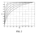
- FIG. 2 is a graph of the results obtained in practicing the first detection step that is proposed in accordance with a preferred embodiment of the invention.
- Each curve represents an operating characteristic of the RF receiver -Receiver Operating Characteristic or ROC-; each point of the ROC curve is determined by the probability of detection (Pd) versus the probability of False Alarm (Pfa).
- Pd probability of detection
- Pfa probability of False Alarm
- the target spectrum (TS) consists of a BPSK signal with 4 samples per symbol and a frequency of 0.20.
- FIG 3 is a graph of the results obtained in practicing the first detection step that is proposed according to a preferred embodiment of the invention.
- the scenario is the same as in Figure 2 but now there is interference at frequency 0.23.
- Each curve represents a ROC curve for a different SNR value.
- SNR ranges from -11 dB to -6 dB.
- the TS is a BPSK signal with 4 samples per symbol and a frequency of 0.20.
- the sensing errors decrease the system throughput because the miss-detection causes collision between the signals received from the RF transmitting station (1) - primary users- and the jammers (2) -secondary users-. Then, the false alarm results in the loss of secondary user's opportunities to use the channel.
- the same threshold ⁇ th has been considered for both the probability of detection (Pd) and the probability of False Alarm (Pfa).
- the range of this threshold ⁇ th is ⁇ th ⁇ [ ⁇ 2 - ⁇ n , ⁇ + ⁇ s ], being ⁇ 2 equal to the noise power, ⁇ equal to the target power, ⁇ n , and ⁇ s being the noise and candidate power variance estimated values respectively.
- the threshold range has been sampled in a logarithmic way. The curves depicted in Figures 2 and 3 are obtained when determining the presence of the TS by estimating the minimum value of the geodesic distance ⁇ GEO and comparing it with the threshold ⁇ th .
- Figure 4 shows the performance of the second step that is proposed in accordance with a preferred embodiment of the invention.
- the values of the normalized power (Px(w)) depicted in Figure 4 are obtained by applying equation 2, i.e, here Px (w) - ⁇ MMSE .
- Figure 5 shows the TS estimation that is provided by the improved filter bank technique described in "Candidate Spectral Estimation for Cognitive Radio" by Rojas et al. [see Proceedings of the 11th WSEAS International Conference on Communications, pp. 8, July 2007 ].
- FIG. 6 shows the performance of 3 classical filter bank approaches, from top to down: periodogram, Maximum Likelihood Method (MLM) and Normalized MLM (NMLM).
- MLM Maximum Likelihood Method
- NMLM Normalized MLM
- the scenario is the same as in Figure 4 .
- Each plot represents the aforementioned normalized power (Px(w)).
Landscapes
- Engineering & Computer Science (AREA)
- Computer Networks & Wireless Communication (AREA)
- Radar, Positioning & Navigation (AREA)
- Remote Sensing (AREA)
- Signal Processing (AREA)
- Physics & Mathematics (AREA)
- General Physics & Mathematics (AREA)
- Monitoring And Testing Of Transmission In General (AREA)
- Noise Elimination (AREA)
- Radar Systems Or Details Thereof (AREA)
- Position Fixing By Use Of Radio Waves (AREA)
Claims (8)
- Procédé de détection de la forme spectrale de signaux de radiofréquence comprenant :- prise d'un nombre N d'échantillons dans un signal de données d'entrée,- calcul d'une matrice de corrélation de données (RD) de dimensions QxQ pour Q parmi N échantillons,- calcul d'une matrice de corrélation cible (RT) d'un spectre cible (TS) à détecter dans le signal de données d'entrée,
procédé caractérisé en ce qu'il comprend en outre- la détermination de la présence ou non du spectre cible (TS) dans le signal de données d'entrée en comparant à un seuil de comparaison une variable de détection (γGEO) qui est la distance géodésique minimale,- calcul de la variable de détection (γGEO) qui minimise la distance géodésique entre la matrice de corrélation cible (RT) et la matrice de corrélation de données (RD) telle quedans laquelle det [RT] et det [RD] représentent le déterminant de la matrice de corrélation cible (RT) et celui de la matrice de corrélation de données (RD) et Q est la dimension de la cible et des matrices de corrélation de données (RT, RD).
- Procédé selon la revendication 1,
caractérisé en ce que
le seuil de comparaison pour déterminer la présence du spectre cible (TS) est γth ∈ [σ2 - δn,γ + δs] formule dans laquelle
γ est la puissance de la cible,
σ2 est la puissance de bruit,
δn est la valeur estimée de la variance de la puissance de bruit σ2, et
δs est la valeur estimée de la variance de la puissance de cible γ. - Procédé de localisation des formes spectrales comprenant la détection d'un spectre cible (TS) selon l'une quelconque des revendications 1 et 2,
caractérisé en outre par
une étape de balayage dans une bande de fréquence intéressante, centrée sur une fréquence de balayage pour déterminer une fréquence porteuse du spectre cible (TS),
l'étape de balayage comprenant les étapes suivantes :
* calculer un vecteur de fréquence de balayage (s) défini tel que s = [1 exp(jw)...exp(j(Q-1)w],
relation dans laquelle
j représente l'unité imaginaire,
Q est la dimension de la cible et des matrices de corrélation (RT, RD), et
W égal 2πf, f étant la fréquence de balayage,
* calculer une matrice de corrélation modulée de la cible (RTM) telle que
dans laquelle □ représente le produit de Hadamard,
sH est la matrice hermitienne du vecteur de fréquence de balayage (s) et γ est un facteur d'échelle,
* localiser le vecteur de fréquence de balayage (s) dans la matrice de corrélation modulée de la cible (RTM) comme bande de fréquence intéressante,
* calculer la matrice de l'erreur moyenne carrée minimale de la matrice de corrélation modulée de cible (RTM) et la matrice de corrélation de cible (RT),
* minimiser la norme de Frobenius de la matrice des erreurs moyennes carrées minimales en calculant un rapport de trace (γMMSE) tel que
relation dans laquelle Trace ( ) représente l'opérateur trace et est appliqué à la matrice de corrélation modulée de cible (RTM) et à la matrice de corrélation de données (RD), * calculer le vecteur de fréquence de balayage (s) à la fréquence à laquelle le rapport de trace (γMMSE) est à sa valeur maximale. - Procédé selon la revendication 3,
caractérisé en ce qu'il comprend en outre l'étape suivante :- estimer un niveau de puissance normalisé Px(w) du spectre cible (TS) comme valeur maximum du rapport de trace (γMMSE). - Dispositif de traitement de signal configuré pour prendre des échantillons dans un signal de données d'entrée avec une fréquence de bande de base et comprenant :- un détecteur de spectre cible configuré pour réaliser les étapes du procédé selon les revendications 1 et 2.
- Dispositif de traitement de signal selon la revendication 5, caractérisé en ce qu'il comprend en outre- un dispositif de localisation de spectre cible relié au détecteur de spectre cible et configuré pour implémenter les étapes du procédé définies selon les revendications 3 et 4 lorsque le spectre cible est détecté.
- Récepteur radiofréquence comprenant :- un circuit avant avec des moyens pour recevoir les signaux de radiofréquence dans une bande de fréquence et obtenir un signal de données de sortie dans la bande de fréquence, et- le dispositif de traitement de signal selon l'une quelconque des revendications 5-6 et auquel le circuit avant fournit le signal de données d'entrée.
- Programme d'ordinateur comportant un code programme d'ordinateur adapté pour exécuter les étapes du procédé selon l'une quelconque des revendications 1 à 4, lorsque le programme est déroulé sur un ordinateur, un processeur de signaux numériques, un circuit FPGA, un circuit ASIC, un microprocesseur, un microcontrôleur ou n'importe quelle autre forme de circuit programmable.
Applications Claiming Priority (2)
| Application Number | Priority Date | Filing Date | Title |
|---|---|---|---|
| ES200801636 | 2008-05-30 | ||
| PCT/EP2008/058098 WO2009143902A1 (fr) | 2008-05-30 | 2008-06-25 | Dispositif de traitement de signal et procédé pour détecter et localiser des formes spectrales |
Publications (2)
| Publication Number | Publication Date |
|---|---|
| EP2297588A1 EP2297588A1 (fr) | 2011-03-23 |
| EP2297588B1 true EP2297588B1 (fr) | 2011-11-23 |
Family
ID=40266164
Family Applications (1)
| Application Number | Title | Priority Date | Filing Date |
|---|---|---|---|
| EP08761373A Not-in-force EP2297588B1 (fr) | 2008-05-30 | 2008-06-25 | Dispositif de traitement de signal et procédé pour détecter et localiser des formes spectrales |
Country Status (5)
| Country | Link |
|---|---|
| US (1) | US8290459B2 (fr) |
| EP (1) | EP2297588B1 (fr) |
| AT (1) | ATE534915T1 (fr) |
| ES (1) | ES2379131T3 (fr) |
| WO (1) | WO2009143902A1 (fr) |
Families Citing this family (11)
| Publication number | Priority date | Publication date | Assignee | Title |
|---|---|---|---|---|
| US8670493B2 (en) * | 2005-06-22 | 2014-03-11 | Eices Research, Inc. | Systems and/or methods of increased privacy wireless communications |
| USRE47633E1 (en) | 2005-06-22 | 2019-10-01 | Odyssey Wireless Inc. | Systems/methods of conducting a financial transaction using a smartphone |
| US8233554B2 (en) | 2010-03-29 | 2012-07-31 | Eices Research, Inc. | Increased capacity communications for OFDM-based wireless communications systems/methods/devices |
| US9374746B1 (en) | 2008-07-07 | 2016-06-21 | Odyssey Wireless, Inc. | Systems/methods of spatial multiplexing |
| US9559417B1 (en) * | 2010-10-29 | 2017-01-31 | The Boeing Company | Signal processing |
| US9054901B2 (en) * | 2012-03-07 | 2015-06-09 | Harris Corporation | Simplified blind signal detector |
| CN105891600B (zh) * | 2015-01-23 | 2019-05-21 | 北京空间飞行器总体设计部 | 四相相移键控信号频谱估计方法 |
| US9935615B2 (en) * | 2015-09-22 | 2018-04-03 | Intel Corporation | RLS-DCD adaptation hardware accelerator for interference cancellation in full-duplex wireless systems |
| US10193683B2 (en) | 2016-07-20 | 2019-01-29 | Intel Corporation | Methods and devices for self-interference cancelation |
| CN108344895B (zh) * | 2018-02-22 | 2020-05-12 | 国网辽宁省电力有限公司电力科学研究院 | 信号检测方法及装置 |
| CN109655804B (zh) * | 2019-01-24 | 2022-11-22 | 南京航空航天大学 | 一种基于奇异值分解的临近目标相对距离估计方法 |
Family Cites Families (5)
| Publication number | Priority date | Publication date | Assignee | Title |
|---|---|---|---|---|
| US7010052B2 (en) * | 2001-04-16 | 2006-03-07 | The Ohio University | Apparatus and method of CTCM encoding and decoding for a digital communication system |
| US7346013B2 (en) * | 2002-07-18 | 2008-03-18 | Coherent Logix, Incorporated | Frequency domain equalization of communication signals |
| EP2082245A1 (fr) * | 2006-11-17 | 2009-07-29 | Nokia Corporation | Procédé et appareil pour détection hf de transitoire par approche par étapes et économie d'énergie de capteur |
| US7751494B2 (en) * | 2007-06-05 | 2010-07-06 | Texas Instruments Incorporated | Reduced search space technique for codeword selection |
| US7769098B2 (en) * | 2007-06-05 | 2010-08-03 | Texas Instruments Incorporated | Low complexity precoding matrix selection |
-
2008
- 2008-06-25 WO PCT/EP2008/058098 patent/WO2009143902A1/fr not_active Ceased
- 2008-06-25 AT AT08761373T patent/ATE534915T1/de active
- 2008-06-25 ES ES08761373T patent/ES2379131T3/es active Active
- 2008-06-25 EP EP08761373A patent/EP2297588B1/fr not_active Not-in-force
- 2008-06-25 US US12/995,336 patent/US8290459B2/en not_active Expired - Fee Related
Also Published As
| Publication number | Publication date |
|---|---|
| WO2009143902A1 (fr) | 2009-12-03 |
| US8290459B2 (en) | 2012-10-16 |
| US20110143700A1 (en) | 2011-06-16 |
| EP2297588A1 (fr) | 2011-03-23 |
| ES2379131T3 (es) | 2012-04-23 |
| ATE534915T1 (de) | 2011-12-15 |
Similar Documents
| Publication | Publication Date | Title |
|---|---|---|
| US8290459B2 (en) | Signal processing device and method for detecting and locating spectral shapes | |
| US10879946B1 (en) | Weak signal processing systems and methods | |
| US8699971B1 (en) | System for specific emitter identification | |
| Wang et al. | Multiantenna-assisted spectrum sensing for cognitive radio | |
| Cohen et al. | Spectrum sharing radar: Coexistence via Xampling | |
| US8060047B2 (en) | Signal frequency band detection device | |
| EP1863188B1 (fr) | Détecteur de la durée de réception d'un signal | |
| US9057772B1 (en) | Referenced-based radio frequency feature estimation | |
| US10623215B2 (en) | Process for tunnelized cyclostationary to achieve low-energy spectrum sensing | |
| EP2514155B1 (fr) | Estimation hybride du canal de tranmission en utilisant des techniques de corrélation et la méthode des moindres carrés | |
| WO2008055094A2 (fr) | Procédé et appareil permettant de supprimer des réponses parasites dans un système de communication à multiplexage par répartition orthogonale de la fréquence | |
| WO2004097449A1 (fr) | Radiogoniometrie pour sources de co-canaux multiples | |
| da Silva et al. | Radio frequency interference detection using nonnegative matrix factorization | |
| EP2838205A2 (fr) | Atténuation adaptative d'interférence de fréquence radio à génération de plateforme | |
| Guo et al. | A robust RF fingerprint extraction scheme for GNSS spoofing detection | |
| US8488578B1 (en) | Identifying a CDMA scrambling code | |
| Duan et al. | Saturated interference in SAR: Theoretical analysis and suppression solutions | |
| Henninger et al. | Target detection for ISAC with TDD transmission | |
| GB2506711A (en) | An adaptive beamformer which uses signal envelopes to correct steering | |
| CN119010932B (zh) | 一种抗脉冲噪声的核相关系数信号检测方法 | |
| US8406353B1 (en) | Signal sequence detection in presence of carrier or narrow band transmissions | |
| CN114397649B (zh) | 一种基于子载波的目标匹配方法 | |
| US20030227410A1 (en) | Antenna processing method for potentially non-centered cyclostationary signals | |
| Argyriou | Passive angle-Doppler profile estimation for narrowband digitally modulated wireless signals | |
| US8743854B1 (en) | Signal separation and SINR enhancement |
Legal Events
| Date | Code | Title | Description |
|---|---|---|---|
| PUAI | Public reference made under article 153(3) epc to a published international application that has entered the european phase |
Free format text: ORIGINAL CODE: 0009012 |
|
| 17P | Request for examination filed |
Effective date: 20101228 |
|
| AK | Designated contracting states |
Kind code of ref document: A1 Designated state(s): AT BE BG CH CY CZ DE DK EE ES FI FR GB GR HR HU IE IS IT LI LT LU LV MC MT NL NO PL PT RO SE SI SK TR |
|
| AX | Request for extension of the european patent |
Extension state: AL BA MK RS |
|
| GRAP | Despatch of communication of intention to grant a patent |
Free format text: ORIGINAL CODE: EPIDOSNIGR1 |
|
| RTI1 | Title (correction) |
Free format text: SIGNAL PROCESSING DEVICE AND METHOD FOR DETECTING AND LOCATING SPECTRAL SHAPES |
|
| DAX | Request for extension of the european patent (deleted) | ||
| GRAS | Grant fee paid |
Free format text: ORIGINAL CODE: EPIDOSNIGR3 |
|
| GRAA | (expected) grant |
Free format text: ORIGINAL CODE: 0009210 |
|
| AK | Designated contracting states |
Kind code of ref document: B1 Designated state(s): AT BE BG CH CY CZ DE DK EE ES FI FR GB GR HR HU IE IS IT LI LT LU LV MC MT NL NO PL PT RO SE SI SK TR |
|
| REG | Reference to a national code |
Ref country code: GB Ref legal event code: FG4D |
|
| REG | Reference to a national code |
Ref country code: CH Ref legal event code: EP |
|
| REG | Reference to a national code |
Ref country code: IE Ref legal event code: FG4D |
|
| REG | Reference to a national code |
Ref country code: DE Ref legal event code: R096 Ref document number: 602008011572 Country of ref document: DE Effective date: 20120209 |
|
| REG | Reference to a national code |
Ref country code: NL Ref legal event code: VDEP Effective date: 20111123 |
|
| REG | Reference to a national code |
Ref country code: ES Ref legal event code: FG2A Ref document number: 2379131 Country of ref document: ES Kind code of ref document: T3 Effective date: 20120423 |
|
| LTIE | Lt: invalidation of european patent or patent extension |
Effective date: 20111123 |
|
| PG25 | Lapsed in a contracting state [announced via postgrant information from national office to epo] |
Ref country code: NO Free format text: LAPSE BECAUSE OF FAILURE TO SUBMIT A TRANSLATION OF THE DESCRIPTION OR TO PAY THE FEE WITHIN THE PRESCRIBED TIME-LIMIT Effective date: 20120223 Ref country code: LT Free format text: LAPSE BECAUSE OF FAILURE TO SUBMIT A TRANSLATION OF THE DESCRIPTION OR TO PAY THE FEE WITHIN THE PRESCRIBED TIME-LIMIT Effective date: 20111123 Ref country code: IS Free format text: LAPSE BECAUSE OF FAILURE TO SUBMIT A TRANSLATION OF THE DESCRIPTION OR TO PAY THE FEE WITHIN THE PRESCRIBED TIME-LIMIT Effective date: 20120323 |
|
| PG25 | Lapsed in a contracting state [announced via postgrant information from national office to epo] |
Ref country code: HR Free format text: LAPSE BECAUSE OF FAILURE TO SUBMIT A TRANSLATION OF THE DESCRIPTION OR TO PAY THE FEE WITHIN THE PRESCRIBED TIME-LIMIT Effective date: 20111123 Ref country code: GR Free format text: LAPSE BECAUSE OF FAILURE TO SUBMIT A TRANSLATION OF THE DESCRIPTION OR TO PAY THE FEE WITHIN THE PRESCRIBED TIME-LIMIT Effective date: 20120224 Ref country code: LV Free format text: LAPSE BECAUSE OF FAILURE TO SUBMIT A TRANSLATION OF THE DESCRIPTION OR TO PAY THE FEE WITHIN THE PRESCRIBED TIME-LIMIT Effective date: 20111123 Ref country code: NL Free format text: LAPSE BECAUSE OF FAILURE TO SUBMIT A TRANSLATION OF THE DESCRIPTION OR TO PAY THE FEE WITHIN THE PRESCRIBED TIME-LIMIT Effective date: 20111123 Ref country code: SE Free format text: LAPSE BECAUSE OF FAILURE TO SUBMIT A TRANSLATION OF THE DESCRIPTION OR TO PAY THE FEE WITHIN THE PRESCRIBED TIME-LIMIT Effective date: 20111123 Ref country code: BE Free format text: LAPSE BECAUSE OF FAILURE TO SUBMIT A TRANSLATION OF THE DESCRIPTION OR TO PAY THE FEE WITHIN THE PRESCRIBED TIME-LIMIT Effective date: 20111123 Ref country code: SI Free format text: LAPSE BECAUSE OF FAILURE TO SUBMIT A TRANSLATION OF THE DESCRIPTION OR TO PAY THE FEE WITHIN THE PRESCRIBED TIME-LIMIT Effective date: 20111123 Ref country code: PT Free format text: LAPSE BECAUSE OF FAILURE TO SUBMIT A TRANSLATION OF THE DESCRIPTION OR TO PAY THE FEE WITHIN THE PRESCRIBED TIME-LIMIT Effective date: 20120323 |
|
| PG25 | Lapsed in a contracting state [announced via postgrant information from national office to epo] |
Ref country code: CY Free format text: LAPSE BECAUSE OF FAILURE TO SUBMIT A TRANSLATION OF THE DESCRIPTION OR TO PAY THE FEE WITHIN THE PRESCRIBED TIME-LIMIT Effective date: 20111123 |
|
| PG25 | Lapsed in a contracting state [announced via postgrant information from national office to epo] |
Ref country code: DK Free format text: LAPSE BECAUSE OF FAILURE TO SUBMIT A TRANSLATION OF THE DESCRIPTION OR TO PAY THE FEE WITHIN THE PRESCRIBED TIME-LIMIT Effective date: 20111123 Ref country code: EE Free format text: LAPSE BECAUSE OF FAILURE TO SUBMIT A TRANSLATION OF THE DESCRIPTION OR TO PAY THE FEE WITHIN THE PRESCRIBED TIME-LIMIT Effective date: 20111123 Ref country code: BG Free format text: LAPSE BECAUSE OF FAILURE TO SUBMIT A TRANSLATION OF THE DESCRIPTION OR TO PAY THE FEE WITHIN THE PRESCRIBED TIME-LIMIT Effective date: 20120223 Ref country code: CZ Free format text: LAPSE BECAUSE OF FAILURE TO SUBMIT A TRANSLATION OF THE DESCRIPTION OR TO PAY THE FEE WITHIN THE PRESCRIBED TIME-LIMIT Effective date: 20111123 Ref country code: SK Free format text: LAPSE BECAUSE OF FAILURE TO SUBMIT A TRANSLATION OF THE DESCRIPTION OR TO PAY THE FEE WITHIN THE PRESCRIBED TIME-LIMIT Effective date: 20111123 |
|
| PG25 | Lapsed in a contracting state [announced via postgrant information from national office to epo] |
Ref country code: IT Free format text: LAPSE BECAUSE OF FAILURE TO SUBMIT A TRANSLATION OF THE DESCRIPTION OR TO PAY THE FEE WITHIN THE PRESCRIBED TIME-LIMIT Effective date: 20111123 Ref country code: PL Free format text: LAPSE BECAUSE OF FAILURE TO SUBMIT A TRANSLATION OF THE DESCRIPTION OR TO PAY THE FEE WITHIN THE PRESCRIBED TIME-LIMIT Effective date: 20111123 Ref country code: RO Free format text: LAPSE BECAUSE OF FAILURE TO SUBMIT A TRANSLATION OF THE DESCRIPTION OR TO PAY THE FEE WITHIN THE PRESCRIBED TIME-LIMIT Effective date: 20111123 |
|
| REG | Reference to a national code |
Ref country code: AT Ref legal event code: MK05 Ref document number: 534915 Country of ref document: AT Kind code of ref document: T Effective date: 20111123 |
|
| PLBE | No opposition filed within time limit |
Free format text: ORIGINAL CODE: 0009261 |
|
| STAA | Information on the status of an ep patent application or granted ep patent |
Free format text: STATUS: NO OPPOSITION FILED WITHIN TIME LIMIT |
|
| 26N | No opposition filed |
Effective date: 20120824 |
|
| REG | Reference to a national code |
Ref country code: DE Ref legal event code: R097 Ref document number: 602008011572 Country of ref document: DE Effective date: 20120824 |
|
| PG25 | Lapsed in a contracting state [announced via postgrant information from national office to epo] |
Ref country code: MC Free format text: LAPSE BECAUSE OF NON-PAYMENT OF DUE FEES Effective date: 20120630 Ref country code: AT Free format text: LAPSE BECAUSE OF FAILURE TO SUBMIT A TRANSLATION OF THE DESCRIPTION OR TO PAY THE FEE WITHIN THE PRESCRIBED TIME-LIMIT Effective date: 20111123 |
|
| REG | Reference to a national code |
Ref country code: CH Ref legal event code: PL |
|
| REG | Reference to a national code |
Ref country code: CH Ref legal event code: PL |
|
| REG | Reference to a national code |
Ref country code: IE Ref legal event code: MM4A |
|
| PG25 | Lapsed in a contracting state [announced via postgrant information from national office to epo] |
Ref country code: IE Free format text: LAPSE BECAUSE OF NON-PAYMENT OF DUE FEES Effective date: 20120625 Ref country code: CH Free format text: LAPSE BECAUSE OF NON-PAYMENT OF DUE FEES Effective date: 20120630 Ref country code: LI Free format text: LAPSE BECAUSE OF NON-PAYMENT OF DUE FEES Effective date: 20120630 |
|
| PG25 | Lapsed in a contracting state [announced via postgrant information from national office to epo] |
Ref country code: FI Free format text: LAPSE BECAUSE OF FAILURE TO SUBMIT A TRANSLATION OF THE DESCRIPTION OR TO PAY THE FEE WITHIN THE PRESCRIBED TIME-LIMIT Effective date: 20111123 |
|
| PG25 | Lapsed in a contracting state [announced via postgrant information from national office to epo] |
Ref country code: MT Free format text: LAPSE BECAUSE OF FAILURE TO SUBMIT A TRANSLATION OF THE DESCRIPTION OR TO PAY THE FEE WITHIN THE PRESCRIBED TIME-LIMIT Effective date: 20111123 |
|
| PG25 | Lapsed in a contracting state [announced via postgrant information from national office to epo] |
Ref country code: TR Free format text: LAPSE BECAUSE OF FAILURE TO SUBMIT A TRANSLATION OF THE DESCRIPTION OR TO PAY THE FEE WITHIN THE PRESCRIBED TIME-LIMIT Effective date: 20111123 |
|
| PG25 | Lapsed in a contracting state [announced via postgrant information from national office to epo] |
Ref country code: LU Free format text: LAPSE BECAUSE OF NON-PAYMENT OF DUE FEES Effective date: 20120625 |
|
| PG25 | Lapsed in a contracting state [announced via postgrant information from national office to epo] |
Ref country code: HU Free format text: LAPSE BECAUSE OF FAILURE TO SUBMIT A TRANSLATION OF THE DESCRIPTION OR TO PAY THE FEE WITHIN THE PRESCRIBED TIME-LIMIT Effective date: 20080625 |
|
| REG | Reference to a national code |
Ref country code: FR Ref legal event code: PLFP Year of fee payment: 9 |
|
| PGFP | Annual fee paid to national office [announced via postgrant information from national office to epo] |
Ref country code: DE Payment date: 20160622 Year of fee payment: 9 Ref country code: GB Payment date: 20160621 Year of fee payment: 9 Ref country code: ES Payment date: 20160617 Year of fee payment: 9 |
|
| PGFP | Annual fee paid to national office [announced via postgrant information from national office to epo] |
Ref country code: FR Payment date: 20160628 Year of fee payment: 9 |
|
| REG | Reference to a national code |
Ref country code: DE Ref legal event code: R119 Ref document number: 602008011572 Country of ref document: DE |
|
| GBPC | Gb: european patent ceased through non-payment of renewal fee |
Effective date: 20170625 |
|
| REG | Reference to a national code |
Ref country code: FR Ref legal event code: ST Effective date: 20180228 |
|
| PG25 | Lapsed in a contracting state [announced via postgrant information from national office to epo] |
Ref country code: GB Free format text: LAPSE BECAUSE OF NON-PAYMENT OF DUE FEES Effective date: 20170625 Ref country code: DE Free format text: LAPSE BECAUSE OF NON-PAYMENT OF DUE FEES Effective date: 20180103 |
|
| PG25 | Lapsed in a contracting state [announced via postgrant information from national office to epo] |
Ref country code: FR Free format text: LAPSE BECAUSE OF NON-PAYMENT OF DUE FEES Effective date: 20170630 |
|
| REG | Reference to a national code |
Ref country code: ES Ref legal event code: FD2A Effective date: 20181112 |
|
| PG25 | Lapsed in a contracting state [announced via postgrant information from national office to epo] |
Ref country code: ES Free format text: LAPSE BECAUSE OF NON-PAYMENT OF DUE FEES Effective date: 20170626 |