EP2297831B1 - Appareil de protection - Google Patents
Appareil de protection Download PDFInfo
- Publication number
- EP2297831B1 EP2297831B1 EP08802900.4A EP08802900A EP2297831B1 EP 2297831 B1 EP2297831 B1 EP 2297831B1 EP 08802900 A EP08802900 A EP 08802900A EP 2297831 B1 EP2297831 B1 EP 2297831B1
- Authority
- EP
- European Patent Office
- Prior art keywords
- voltage
- current
- direct
- current valve
- network
- Prior art date
- Legal status (The legal status is an assumption and is not a legal conclusion. Google has not performed a legal analysis and makes no representation as to the accuracy of the status listed.)
- Active
Links
Images
Classifications
-
- H—ELECTRICITY
- H02—GENERATION; CONVERSION OR DISTRIBUTION OF ELECTRIC POWER
- H02H—EMERGENCY PROTECTIVE CIRCUIT ARRANGEMENTS
- H02H9/00—Emergency protective circuit arrangements for limiting excess current or voltage without disconnection
- H02H9/04—Emergency protective circuit arrangements for limiting excess current or voltage without disconnection responsive to excess voltage
- H02H9/042—Emergency protective circuit arrangements for limiting excess current or voltage without disconnection responsive to excess voltage comprising means to limit the absorbed power or indicate damaged over-voltage protection device
Definitions
- the present invention relates to an apparatus for protecting equipment connected to a high voltage direct current line, said apparatus being configured to obtain said protection by having ground connection means enabling connecting of said line to the ground, said ground connecting means comprising a current valve having at least one semiconductor device of turn-off type connected with a forward conducting direction thereof towards ground and at least one rectifying member connected in anti-parallel therewith, said apparatus further comprising a control unit configured to control said at least one semiconductor device to conduct for draining current from said line and by that protecting a said equipment.
- High voltage direct current line is to be interpreted broadly and includes in this context any line feeding electric power in the form of a direct current to any type of equipment and which is on high voltage potential, i.e. a voltage of at least 1 kV but normally higher, such as well in the order of 100 kV to 1200 kV.
- said line does not have to be a direct voltage network in a plant for transmitting electric power between converter stations, although that is a particular application of the present invention.
- Protecting is here also to be interpreted broadly, and this may for example involve a prevention that the voltage on said line will reach too high levels or that the current fed to said equipment will exceed a predetermined level. Thus, it may be a question of obtaining a better or more preferred operation of said equipment by said "protection”, but it may also be a protection of the equipment for preventing failure thereof.
- the converter stations are each connected to an alternating voltage network, which may include generators of electric power and/or consumers of electric power, and the converter stations have converters adapted to convert direct voltage into alternating voltage and conversely.
- the level of the voltage of the direct voltage network is defined by one or more capacitors, and if this level gets too high said at least one semiconductor device of said current valve of the apparatus may be turned on and the capacitor may be discharged by draining current to the ground and by that the voltage on the direct voltage network may be reduced to a suitable level, whereupon the semiconductor device is turned off.
- the object of the present invention is to provide an apparatus of the type defined in the introduction, which is improved in at least some aspect with respect to such apparatuses already known.
- ground connecting means further comprises at least one surge arrester configured to connect said current valve to said line and having a threshold voltage being at least 0.5 times the nominal voltage of said line to which the apparatus is configured to be connected, a resistor connected in parallel with said surge arrester and in series with said current valve and a second surge arrester connected in series with the surge arrester first mentioned and in parallel with said current valve and connected to ground.
- the current valve had to withstand the full voltage of the high voltage direct current line, but by connecting said surge arrester in series with the current valve the voltage rating of the current valve may be reduced, since the surge arrester will normally take up a substantial part of the direct voltage of said line.
- the current valve will have a high number of semiconductor devices connected in series for being able to together hold the voltage to be held thereby, and the semiconductor devices will all be turned on and turned off simultaneously so as to function as one single switch.
- the present invention makes it possible to reduce said number of semiconductor devices connected in series considerably and involves by that also a considerable saving of costs.
- the current valve will be ordered to conduct, and the voltage of the high voltage direct current line will then be reduced by the surge arrester.
- Threehold voltage with respect to the voltage across said surge arrester here means the voltage level above which the surge arrester will change from conducting a very low leakage current to conduct a strongly increased current.
- said at least one surge arrester has a threshold voltage being at least 0.8 times said nominal voltage. This means that a big part of the dc voltage of said line will be taken up by the surge arrester, so that the current valve will then only take a fraction thereof.
- said at least one surge arrester has a threshold voltage being 0.8 to 1.5 or 1.0 to 1.3 times said nominal voltage. These are suitable levels of said threshold voltage of the surge arrester for obtaining a substantial lowering of the voltage rating of said current valve and also obtaining a suitable voltage of the high voltage direct current line with respect to ground through the surge arrester when the current valve is conducting.
- said ground connecting means further comprises a resistor connected in parallel with said surge arrester and in series with said current valve and a second surge arrester connected in series with the surge arrester first mentioned and in parallel with said current valve and connected to ground.
- This configuration of said ground connecting means obtains a favourable balancing of leakage currents in both the first mentioned surge arrester and the current valve.
- Said resistor will supply the leakage current to the current valve, whereas said second surge arrester will both protect the current valve and balance the leakage current from the surge arrester connected in series with the current valve.
- said current valve comprises a plurality, advantageously at least 5 and preferably at least 10, of said semiconductor devices connected in series. The number of these semiconductor devices will in an apparatus according to the invention be considerably reduced thanks to the arrangement of said surge arrester in said ground connecting means and by that costs will be saved.
- said current valve comprises at least one high ohmic resistor connected in parallel with said series connection of semiconductor devices for voltage distribution inside the current valve.
- the arrangement of this high ohmic resistor results in an even voltage distribution inside the current valve and by that an increased reliability and a reduced risk of failure of any semiconductor device in the current valve.
- said at least one semiconductor device is an IGBT (Insulating Gate Bipolar Transistor), an IGCT (Integrated Gate Commutated Thyristor) or a GTO (Gate Turn-Off Thyristor).
- IGBT Insulating Gate Bipolar Transistor
- IGCT Integrated Gate Commutated Thyristor
- GTO Gate Turn-Off Thyristor
- said ground connecting means are configured to connect to a direct voltage network for transmitting High Voltage Direct Current (HVDC), where the direct voltage network is connected to a converter station having at least one Voltage Source Converter having an alternating voltage side connected to an alternating voltage network and being configured to convert alternating voltage into direct voltage and conversely.
- HVDC High Voltage Direct Current
- An apparatus of this type is particularly advantageous when configured for this application, since the voltage levels of the direct voltage network will be high and by that considerable saving of costs may be obtained for such an apparatus. It may then also be efficiently used to control the voltage level of the direct voltage network and by that of the direct voltage side of said Voltage Source Converter.
- the apparatus comprises a detector configured to detect the level of the voltage on said direct voltage network and to send information thereabout to said control unit, and the control unit is configured to carry out the control of the current valve in dependence upon information from said detector. This means that the apparatus may efficiently control the level of the direct voltage on said direct voltage network.
- control unit is configured to control the current valve to conduct if the voltage detected by the detector exceeds a predetermined level. Accordingly, the apparatus may be used to ensure that the voltage on said direct voltage network does not get too high.
- the apparatus comprises a detector configured to measure the current flowing in said direct voltage network and to send information thereabout to said control unit, and the control unit is configured to control said current valve to conduct if the current detected by said detector exceeds a predetermined value.
- the apparatus is configured to protect equipment connected to a High Voltage Direct Current line with a nominal voltage ⁇ 1 kV, ⁇ 100 kV, 100 kV to 1200 kV or 400 kV to 1200 kV.
- the invention also relates to a high voltage arrangement comprising a line configured to conduct a direct current on high voltage potential and through this line feed electric power to equipment belonging to said arrangement, in which the arrangement further comprises an apparatus according to the present invention for protecting said equipment.
- a high voltage arrangement will have a reliable operation by protection of the equipment thereof to an attractively low cost.
- the invention also relates to a plant for transmitting electric power comprising a direct voltage network and at least one alternating voltage network connected thereto through a station, said station being adapted to perform transmitting of electric power between the direct voltage network and the alternating voltage network and comprising at least one Voltage Source Converter adapted to convert direct voltage into alternating voltage and conversely, in which said plant comprises an apparatus according to the present invention connected to said direct voltage network.
- a plant for transmitting electric power comprising a direct voltage network and at least one alternating voltage network connected thereto through a station, said station being adapted to perform transmitting of electric power between the direct voltage network and the alternating voltage network and comprising at least one Voltage Source Converter adapted to convert direct voltage into alternating voltage and conversely, in which said plant comprises an apparatus according to the present invention connected to said direct voltage network.
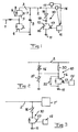
- Fig 1 illustrates very schematically an apparatus according to a first embodiment of the invention for protecting equipment, here illustrated by an alternating voltage network 1 connected to a high voltage direct current line in the form of a direct voltage network 2 being a part of a plant for transmitting electric power through High Voltage Direct Current (HVDC).
- a converter station 3 of this plant having a Voltage Source Converter 4 for converting alternating voltage into direct voltage and conversely connected to the direct voltage network 2 is very schematically illustrated. Only two valves 5, 6 with a semiconductor device 7 of turn-off type and a rectifying member in the form of a diode 8 connected in anti-parallel therewith are shown for one phase of the alternating voltage network.
- a capacitor 9 is arranged for defining the voltage of the direct voltage network 2.
- An apparatus has ground connecting means 10 enabling connecting of the direct voltage network 2 to the ground or earth 11.
- This ground connecting means comprises a current valve 12 having at least one semiconductor device 13 (the symbol therefor may here stand for a number of such semiconductor devices connected in series) of turn-off type connected with a forward conducting direction thereof towards ground and at least one rectifying member 14, such as a rectifying diode, connected in anti-parallel therewith.
- the apparatus also comprises a control unit 15 configured to control said at least one semiconductor device to turn on or turn off.
- the ground connecting means 10 of the apparatus further comprises at least one surge arrester 16, i.e. an unlinear resistor, such as a zinc oxide arrester, configured to connect said current valve 12 to the direct voltage network 2 and having a threshold voltage being at least 0.5 times, preferably at least 0.8 times, and more preferred between 0.8 and 1.5 or between 1.0 and 1.3 times the nominal voltage of the direct voltage network.
- This nominal voltage may for a HVDC plant of this type typically be 100 kV to 1200 kV.
- the apparatus also comprises a detector 17 configured to detect the level of the voltage on the direct voltage network 2 and send information thereabout to the control unit 15, which is configured to carry out the control of the current valve 12 in dependence upon information from said detector 17.
- the apparatus also comprises another detector 18 configured to measure the current flowing in the direct voltage network and to send information thereabout to the control unit 15, which is configured to control the current valve 12 in dependence upon information from this detector 18.
- the current valve 12 will normally be non-conducting and the surge arrester will then take up a big part of the dc voltage and the current valve only a fraction.
- the function of the apparatus may be as follows. We assume that the nominal voltage of the direct voltage network is 100 kV and the threshold voltage of the surge arrester is also 100 kV. When the detector 17 detects a voltage exceeding a predetermined level, such as 130 kV, the control unit controls the current valve to start to conduct for discharging the capacitor 9 as indicated by the arrow 19. The current valve has in this case only to withstand 30% of the nominal dc voltage, since the surge arrester will take 100 kV.
- the control unit 15 may turn the semiconductor devices 13 off when the voltage level on the direct voltage network has reached a desired level, such as said nominal voltage level.
- the control unit 15 may also control the current valve to start to conduct if the detector 18 detects a current exceeding a predetermined value, which may for example be 5000 A. This may for instance be the case if we assume that a wind power plant generating electric power is connected to the alternating voltage side of a converter station connected to the other end not shown of the direct voltage network and this as a consequence of extreme conditions will feed an excessive amount of electric power into the direct voltage network and towards the station 3. By then draining the current to ground through the apparatus according to the present invention, the station 3 and possibly sensitive equipment 1 connected thereto may be protected.
- a predetermined value which may for example be 5000 A.
- Fig 2 illustrates schematically an apparatus according to a second embodiment of the invention which differs from the apparatus shown in Fig 1 by the fact that measures have been taken for balancing the leakage currents of both the surge arrester 16 and the current valve 12. This has been done by connecting a resistor 20 in parallel with the surge arrester 16 and in series with the current valve 12 for supplying leakage current to the current valve 12. Furthermore, a second surge arrester 21 is connected in series with the surge arrester 16 and in parallel with the current valve 12 and connected to ground 11. This second surge arrester will protect the current valve and also balance the leakage current from the surge arrester 16.
- the current valve 12 is provided with high ohmic resistors 22 configured to obtain an even voltage distribution inside the current valve 12.
- FIG 3 illustrates very schematically how an apparatus according to the first embodiment of the invention may be connected to an arbitrary high voltage direct current line 2' connected to any type of equipment 1' to be protected by the possibility to drain current from the line 2' to earth 11 through the ground connecting means 10 of the apparatus.
Landscapes
- Emergency Protection Circuit Devices (AREA)
- Power Conversion In General (AREA)
Claims (13)
- Appareil de protection d'un matériel (1) connecté à une ligne de transport d'énergie à courant continu à haute tension d'un réseau de transport d'énergie à tension continue (2), ledit appareil étant configuré de façon à obtenir ladite protection en ayant un moyen de connexion à la terre (10) permettant la connexion de ladite ligne à la terre (11), ledit moyen de connexion à la terre comprenant une valve de courant (12) ayant au moins un dispositif semi-conducteur (13) du type à blocage connecté avec une direction de conduction dans le sens direct de celui-ci vers la terre et au moins un élément redresseur (14) connecté en anti-parallèle avec celui-ci, ledit appareil comprenant en outre une unité de commande (15) configurée de façon à commander audit au moins un dispositif semi-conducteur (13) de conduire pour drainer le courant de ladite ligne et de protéger ainsi ledit matériel (1),
caractérisé en ce que ledit moyen de connexion à la terre (10) comprend en outre au moins un limiteur de surtension (16) configuré de façon à connecter ladite valve de courant (12) à ladite ligne et ayant une tension de seuil étant au moins 0,5 fois la tension nominale de ladite ligne à laquelle l'appareil est configuré de façon à être connecté, une résistance (20) connectée en parallèle avec ledit limiteur de surtension (16) et en série avec ladite valve de courant (12) et un deuxième limiteur de surtension (21) connecté en série avec le limiteur de surtension (16) mentionné en premier et en parallèle avec ladite valve de courant et connecté à la terre. - Appareil selon la revendication 1, caractérisé en ce que ledit au moins un limiteur de tension (16) a une tension de seuil étant au moins 0,8 fois ladite tension nominale.
- Appareil selon la revendication 1 ou 2, caractérisé en ce que ledit au moins un limiteur de surtension (16) a une tension de seuil étant entre 0,8 et 1,5 fois ou entre 1,0 ° et 1,3 fois ladite tension nominale.
- Appareil selon l'une quelconque des revendications précédentes, caractérisé en ce que ladite valve de courant (12) comprend une pluralité, avantageusement 5 et de préférence au moins 10, desdits dispositifs semi-conducteurs (13) connectés en série.
- Appareil selon la revendication 4, caractérisé en ce que ladite valve de courant (12) comprend au moins une résistance ohmique élevée (22) connectée en parallèle avec ladite connexion en série de dispositifs semi-conducteurs pour la distribution de tension à l'intérieur de la valve de courant.
- Appareil selon l'une quelconque des revendications précédentes, caractérisé en ce que ledit au moins un dispositif semi-conducteur (13) est un transistor bipolaire à porte isolée (IGBT), un thyristor commuté par gâchette intégré (IGCT) ou un thyristor blocable par gâchette (GTO).
- Appareil selon l'une quelconque des revendications précédentes, caractérisé en ce que ledit moyen de connexion à la terre (10) est configuré de façon à connecter à un réseau à tension continue (2) pour transporter un courant continu à haute tension (CCHT), ce réseau à tension continue étant connecté à une station de conversion (3) ayant au moins un convertisseur de source de tension (4) ayant un côté à tension alternative connecté à un réseau à tension alternative (1) et étant configuré de façon à convertir une tension alternative en une tension continue et vice versa.
- Appareil selon la revendication 7, caractérisé en ce qu'il comprend un détecteur (17) configuré de façon à détecter le niveau de la tension sur ledit réseau à tension continue (2) et à envoyer des informations sur celui-ci à ladite unité de commande (15), et en ce que l'unité de commande est configurée de façon à effectuer la commande de la valve de courant (12) en dépendance des informations provenant dudit détecteur.
- Appareil selon la revendication 8, caractérisé en ce que ladite unité de commande (15) est configurée de façon à commander à la valve de courant (12) de conduire si la tension détectée par le détecteur dépasse un niveau prédéterminé.
- Appareil selon l'une quelconque des revendications 7 à 9, caractérisé en ce qu'il comprend un détecteur (18) configuré de façon à mesurer le courant s'écoulant dans ledit réseau à tension continue (2) et à envoyer des informations sur celui-ci à ladite unité de commande (15), et en ce que l'unité de commande est configurée de façon à commander à ladite valve de courant (12) de conduire si le courant détecté par ledit détecteur (18) dépasse une valeur prédéterminée.
- Appareil selon l'une quelconque des revendications précédentes, caractérisé en ce qu'il est configuré de façon à protéger le matériel connecté à une ligne à courant continu à haute tension (2) avec une tension nominale ≥ 1 kV, ≥ 100 kV, de 100 kV à 1200 kV ou de 400 kV à 1200 kV.
- Agencement à haute tension comprenant une ligne de transport d'énergie d'un réseau de transport d'énergie à tension continue (2, 2') et configuré de façon à conduire un courant continu sur un potentiel à haute tension et, au moyen de cette ligne, à alimenter une énergie électrique au matériel (1, 1') appartenant audit agencement, caractérisé en ce que cet agencement comprend en outre un appareil selon l'une quelconque des revendications 1 à 11 pour protéger ledit matériel.
- Installation pour transporter une énergie électrique comprenant un réseau de transport d'énergie à tension continue (2) avec une ligne de transport d'énergie et au moins un réseau à tension alternative (1) connecté à celle-ci par l'intermédiaire d'une station (3), ladite station étant adaptée de façon à effectuer le transport d'énergie électrique entre le réseau à tension continue et le réseau à tension alternative et comprenant au moins un convertisseur de source de tension (4) adapté de façon à convertir une tension continue en une tension alternative et vice versa, caractérisé en ce que cette installation comprend un appareil selon l'une quelconque des revendications 1 à 11 connecté audit réseau à tension continue (2).
Applications Claiming Priority (1)
| Application Number | Priority Date | Filing Date | Title |
|---|---|---|---|
| PCT/EP2008/057155 WO2009149744A1 (fr) | 2008-06-09 | 2008-06-09 | Appareil de protection |
Publications (2)
| Publication Number | Publication Date |
|---|---|
| EP2297831A1 EP2297831A1 (fr) | 2011-03-23 |
| EP2297831B1 true EP2297831B1 (fr) | 2015-01-21 |
Family
ID=40285914
Family Applications (1)
| Application Number | Title | Priority Date | Filing Date |
|---|---|---|---|
| EP08802900.4A Active EP2297831B1 (fr) | 2008-06-09 | 2008-06-09 | Appareil de protection |
Country Status (8)
| Country | Link |
|---|---|
| US (1) | US8467163B2 (fr) |
| EP (1) | EP2297831B1 (fr) |
| KR (1) | KR101191693B1 (fr) |
| CN (1) | CN102057551B (fr) |
| AR (1) | AR072082A1 (fr) |
| CA (1) | CA2725973C (fr) |
| RU (1) | RU2479906C2 (fr) |
| WO (1) | WO2009149744A1 (fr) |
Families Citing this family (9)
| Publication number | Priority date | Publication date | Assignee | Title |
|---|---|---|---|---|
| WO2011023238A1 (fr) * | 2009-08-31 | 2011-03-03 | Abb Technology Ag | Procédé et dispositif de protection contre les surtensions, et système électrique comprenant un tel dispositif |
| CN103181048B (zh) * | 2010-10-29 | 2015-08-19 | Abb技术有限公司 | 接地故障之后的对称hvdc单极输电线的电压平衡 |
| US8890019B2 (en) | 2011-02-05 | 2014-11-18 | Roger Webster Faulkner | Commutating circuit breaker |
| US9537307B2 (en) * | 2011-07-19 | 2017-01-03 | Hamilton Sundstrand Corporation | Overvoltage protection method and device |
| US9088150B2 (en) * | 2012-03-06 | 2015-07-21 | General Electric Company | Overvoltage clipping device for a wind turbine and method |
| CN106602915B (zh) * | 2016-09-28 | 2024-11-05 | 武汉易知鸟科技有限公司 | 一种逆变装置的功率限制电路及逆变装置 |
| US10004123B1 (en) * | 2016-11-02 | 2018-06-19 | Universal Lighting Technologies, Inc. | Failure detection and alerting circuit for a differential mode surge protection device in an LED driver |
| DK3639353T3 (da) * | 2017-07-28 | 2023-11-20 | Siemens Energy Global Gmbh & Co Kg | Impedans for ac-fejlstrømsbehandling til hvdc-omformer |
| CN114388206B (zh) * | 2020-10-16 | 2023-09-15 | 许继集团有限公司 | 一种直流可控避雷器及其使用的电力电子开关 |
Family Cites Families (18)
| Publication number | Priority date | Publication date | Assignee | Title |
|---|---|---|---|---|
| US4571656A (en) * | 1984-01-13 | 1986-02-18 | Dynatech Computer Power, Inc. | Electrical circuit for protection against surge overvoltage of transients |
| WO1988003608A1 (fr) | 1986-11-08 | 1988-05-19 | Robert Bosch Gmbh | Commutateur a haute tension |
| GB2225908B (en) * | 1988-11-11 | 1993-01-13 | Texas Instruments Ltd | Improvements in or relating to overvoltage protection circuits |
| US5189587A (en) * | 1990-07-24 | 1993-02-23 | Square D Company | Dual shunt current regulator |
| GB9021222D0 (en) * | 1990-09-28 | 1990-11-14 | Raychem Ltd | Circuit protection device |
| US5559658A (en) | 1994-09-06 | 1996-09-24 | Eldec Corporation | Solid-state high voltage crowbar circuit |
| US5532635A (en) | 1994-09-12 | 1996-07-02 | Harris Corporation | Voltage clamp circuit and method |
| US6226166B1 (en) * | 1997-11-28 | 2001-05-01 | Erico Lighting Technologies Pty Ltd | Transient overvoltage and lightning protection of power connected equipment |
| US6459559B1 (en) * | 1999-01-14 | 2002-10-01 | Dale Jack Christofersen | Thyristor controlled dynamic voltage suppressor for electric power systems |
| US6226162B1 (en) * | 1999-06-02 | 2001-05-01 | Eaton Corporation | Surge suppression network responsive to the rate of change of power disturbances |
| DE19942023A1 (de) * | 1999-09-03 | 2001-03-08 | Moeller Gmbh | Schaltungsanordnung für den Überspannungsschutz eines Leistungstransistors zur Steuerung einer induktiven Last |
| US20020159212A1 (en) * | 2001-04-25 | 2002-10-31 | Oughton George W. | Voltage protection apparatus and methods using switched clamp circuits |
| JP2006502687A (ja) * | 2002-10-08 | 2006-01-19 | ディセニョ・デ・システマス・エン・シリシオ・ソシエダッド・アノニマ | 電圧サージ保護装置 |
| EP1557923A1 (fr) * | 2004-01-26 | 2005-07-27 | ABB Schweiz AG | Dispositif de protection contre les surtensions pour un circuit à tension continue, et inverseur comportant un tel dispositif |
| FI121492B (fi) | 2005-04-22 | 2010-11-30 | Vacon Oyj | Taajuusmuuttajan ylijännitesuojaus |
| CN2896638Y (zh) * | 2006-02-28 | 2007-05-02 | 上海电器科学研究所(集团)有限公司 | 具有多保护模式的终端电涌保护器 |
| WO2008039120A1 (fr) * | 2006-09-29 | 2008-04-03 | Abb Technology Ltd. | Conversion de lignes ca en lignes ccht |
| WO2011023238A1 (fr) * | 2009-08-31 | 2011-03-03 | Abb Technology Ag | Procédé et dispositif de protection contre les surtensions, et système électrique comprenant un tel dispositif |
-
2008
- 2008-06-09 CA CA2725973A patent/CA2725973C/fr not_active Expired - Fee Related
- 2008-06-09 KR KR1020107027493A patent/KR101191693B1/ko active Active
- 2008-06-09 RU RU2010153994/07A patent/RU2479906C2/ru not_active IP Right Cessation
- 2008-06-09 CN CN200880129691.8A patent/CN102057551B/zh active Active
- 2008-06-09 US US12/997,129 patent/US8467163B2/en active Active
- 2008-06-09 EP EP08802900.4A patent/EP2297831B1/fr active Active
- 2008-06-09 WO PCT/EP2008/057155 patent/WO2009149744A1/fr not_active Ceased
-
2009
- 2009-06-09 AR ARP090102067A patent/AR072082A1/es not_active Application Discontinuation
Also Published As
| Publication number | Publication date |
|---|---|
| RU2479906C2 (ru) | 2013-04-20 |
| AR072082A1 (es) | 2010-08-04 |
| CN102057551A (zh) | 2011-05-11 |
| EP2297831A1 (fr) | 2011-03-23 |
| US20110080679A1 (en) | 2011-04-07 |
| KR101191693B1 (ko) | 2012-10-16 |
| CA2725973A1 (fr) | 2009-12-17 |
| US8467163B2 (en) | 2013-06-18 |
| WO2009149744A1 (fr) | 2009-12-17 |
| KR20110003582A (ko) | 2011-01-12 |
| RU2010153994A (ru) | 2012-07-20 |
| CA2725973C (fr) | 2013-09-17 |
| CN102057551B (zh) | 2013-12-25 |
Similar Documents
| Publication | Publication Date | Title |
|---|---|---|
| US8467163B2 (en) | Protecting apparatus | |
| US8643995B2 (en) | Method and a device for overvoltage protection, and an electric system with such a device | |
| Candelaria et al. | VSC-HVDC system protection: A review of current methods | |
| US9735573B2 (en) | DC-power system with system protection capabilities | |
| US11121542B2 (en) | Protection coordination technique for power converters | |
| US8971070B2 (en) | Interface arrangement between AC and DC systems for reliable opening of the circuit breaker in time | |
| US11909203B2 (en) | DC power distribution architecture and method applicable to data centers | |
| US20160211669A1 (en) | Electric protection on ac side of hvdc | |
| GB2537850B (en) | Bipolar DC power transmission scheme | |
| EP3101748B1 (fr) | Distribution de puissance en courant continu et système de protection | |
| US11509233B1 (en) | Surge voltage protection for a power conversion system | |
| US11431164B2 (en) | Circuit arrangement for combined protection of a load from temporary and transient overvoltages | |
| Carminati et al. | Ground fault analysis of low voltage DC micro-grids with active front-end converter | |
| JP2023092522A (ja) | ハイブリッド回路遮断器 | |
| Carminati et al. | DC and AC ground fault analysis in LVDC microgrids with energy storage systems | |
| US9419428B2 (en) | Protection device for DC collection systems | |
| US8687391B2 (en) | Converter system and method for the operation of such a converter |
Legal Events
| Date | Code | Title | Description |
|---|---|---|---|
| PUAI | Public reference made under article 153(3) epc to a published international application that has entered the european phase |
Free format text: ORIGINAL CODE: 0009012 |
|
| 17P | Request for examination filed |
Effective date: 20110110 |
|
| AK | Designated contracting states |
Kind code of ref document: A1 Designated state(s): AT BE BG CH CY CZ DE DK EE ES FI FR GB GR HR HU IE IS IT LI LT LU LV MC MT NL NO PL PT RO SE SI SK TR |
|
| AX | Request for extension of the european patent |
Extension state: AL BA MK RS |
|
| RIN1 | Information on inventor provided before grant (corrected) |
Inventor name: ASPLUND, GUNNAR |
|
| DAX | Request for extension of the european patent (deleted) | ||
| GRAP | Despatch of communication of intention to grant a patent |
Free format text: ORIGINAL CODE: EPIDOSNIGR1 |
|
| INTG | Intention to grant announced |
Effective date: 20141104 |
|
| GRAS | Grant fee paid |
Free format text: ORIGINAL CODE: EPIDOSNIGR3 |
|
| GRAA | (expected) grant |
Free format text: ORIGINAL CODE: 0009210 |
|
| AK | Designated contracting states |
Kind code of ref document: B1 Designated state(s): AT BE BG CH CY CZ DE DK EE ES FI FR GB GR HR HU IE IS IT LI LT LU LV MC MT NL NO PL PT RO SE SI SK TR |
|
| REG | Reference to a national code |
Ref country code: GB Ref legal event code: FG4D |
|
| REG | Reference to a national code |
Ref country code: CH Ref legal event code: EP |
|
| REG | Reference to a national code |
Ref country code: IE Ref legal event code: FG4D |
|
| REG | Reference to a national code |
Ref country code: DE Ref legal event code: R096 Ref document number: 602008036476 Country of ref document: DE Effective date: 20150305 |
|
| REG | Reference to a national code |
Ref country code: AT Ref legal event code: REF Ref document number: 709539 Country of ref document: AT Kind code of ref document: T Effective date: 20150315 |
|
| REG | Reference to a national code |
Ref country code: NL Ref legal event code: VDEP Effective date: 20150121 |
|
| REG | Reference to a national code |
Ref country code: AT Ref legal event code: MK05 Ref document number: 709539 Country of ref document: AT Kind code of ref document: T Effective date: 20150121 |
|
| REG | Reference to a national code |
Ref country code: FR Ref legal event code: PLFP Year of fee payment: 8 |
|
| REG | Reference to a national code |
Ref country code: LT Ref legal event code: MG4D |
|
| REG | Reference to a national code |
Ref country code: NO Ref legal event code: T2 Effective date: 20150121 |
|
| PG25 | Lapsed in a contracting state [announced via postgrant information from national office to epo] |
Ref country code: LT Free format text: LAPSE BECAUSE OF FAILURE TO SUBMIT A TRANSLATION OF THE DESCRIPTION OR TO PAY THE FEE WITHIN THE PRESCRIBED TIME-LIMIT Effective date: 20150121 Ref country code: SE Free format text: LAPSE BECAUSE OF FAILURE TO SUBMIT A TRANSLATION OF THE DESCRIPTION OR TO PAY THE FEE WITHIN THE PRESCRIBED TIME-LIMIT Effective date: 20150121 Ref country code: BG Free format text: LAPSE BECAUSE OF FAILURE TO SUBMIT A TRANSLATION OF THE DESCRIPTION OR TO PAY THE FEE WITHIN THE PRESCRIBED TIME-LIMIT Effective date: 20150421 Ref country code: HR Free format text: LAPSE BECAUSE OF FAILURE TO SUBMIT A TRANSLATION OF THE DESCRIPTION OR TO PAY THE FEE WITHIN THE PRESCRIBED TIME-LIMIT Effective date: 20150121 Ref country code: FI Free format text: LAPSE BECAUSE OF FAILURE TO SUBMIT A TRANSLATION OF THE DESCRIPTION OR TO PAY THE FEE WITHIN THE PRESCRIBED TIME-LIMIT Effective date: 20150121 Ref country code: ES Free format text: LAPSE BECAUSE OF FAILURE TO SUBMIT A TRANSLATION OF THE DESCRIPTION OR TO PAY THE FEE WITHIN THE PRESCRIBED TIME-LIMIT Effective date: 20150121 |
|
| PG25 | Lapsed in a contracting state [announced via postgrant information from national office to epo] |
Ref country code: GR Free format text: LAPSE BECAUSE OF FAILURE TO SUBMIT A TRANSLATION OF THE DESCRIPTION OR TO PAY THE FEE WITHIN THE PRESCRIBED TIME-LIMIT Effective date: 20150422 Ref country code: PL Free format text: LAPSE BECAUSE OF FAILURE TO SUBMIT A TRANSLATION OF THE DESCRIPTION OR TO PAY THE FEE WITHIN THE PRESCRIBED TIME-LIMIT Effective date: 20150121 Ref country code: IS Free format text: LAPSE BECAUSE OF FAILURE TO SUBMIT A TRANSLATION OF THE DESCRIPTION OR TO PAY THE FEE WITHIN THE PRESCRIBED TIME-LIMIT Effective date: 20150521 Ref country code: LV Free format text: LAPSE BECAUSE OF FAILURE TO SUBMIT A TRANSLATION OF THE DESCRIPTION OR TO PAY THE FEE WITHIN THE PRESCRIBED TIME-LIMIT Effective date: 20150121 Ref country code: NL Free format text: LAPSE BECAUSE OF FAILURE TO SUBMIT A TRANSLATION OF THE DESCRIPTION OR TO PAY THE FEE WITHIN THE PRESCRIBED TIME-LIMIT Effective date: 20150121 Ref country code: AT Free format text: LAPSE BECAUSE OF FAILURE TO SUBMIT A TRANSLATION OF THE DESCRIPTION OR TO PAY THE FEE WITHIN THE PRESCRIBED TIME-LIMIT Effective date: 20150121 |
|
| REG | Reference to a national code |
Ref country code: DE Ref legal event code: R097 Ref document number: 602008036476 Country of ref document: DE |
|
| PG25 | Lapsed in a contracting state [announced via postgrant information from national office to epo] |
Ref country code: RO Free format text: LAPSE BECAUSE OF FAILURE TO SUBMIT A TRANSLATION OF THE DESCRIPTION OR TO PAY THE FEE WITHIN THE PRESCRIBED TIME-LIMIT Effective date: 20150121 Ref country code: EE Free format text: LAPSE BECAUSE OF FAILURE TO SUBMIT A TRANSLATION OF THE DESCRIPTION OR TO PAY THE FEE WITHIN THE PRESCRIBED TIME-LIMIT Effective date: 20150121 Ref country code: CZ Free format text: LAPSE BECAUSE OF FAILURE TO SUBMIT A TRANSLATION OF THE DESCRIPTION OR TO PAY THE FEE WITHIN THE PRESCRIBED TIME-LIMIT Effective date: 20150121 Ref country code: DK Free format text: LAPSE BECAUSE OF FAILURE TO SUBMIT A TRANSLATION OF THE DESCRIPTION OR TO PAY THE FEE WITHIN THE PRESCRIBED TIME-LIMIT Effective date: 20150121 Ref country code: SK Free format text: LAPSE BECAUSE OF FAILURE TO SUBMIT A TRANSLATION OF THE DESCRIPTION OR TO PAY THE FEE WITHIN THE PRESCRIBED TIME-LIMIT Effective date: 20150121 |
|
| PLBE | No opposition filed within time limit |
Free format text: ORIGINAL CODE: 0009261 |
|
| STAA | Information on the status of an ep patent application or granted ep patent |
Free format text: STATUS: NO OPPOSITION FILED WITHIN TIME LIMIT |
|
| 26N | No opposition filed |
Effective date: 20151022 |
|
| PG25 | Lapsed in a contracting state [announced via postgrant information from national office to epo] |
Ref country code: IT Free format text: LAPSE BECAUSE OF FAILURE TO SUBMIT A TRANSLATION OF THE DESCRIPTION OR TO PAY THE FEE WITHIN THE PRESCRIBED TIME-LIMIT Effective date: 20150121 |
|
| PG25 | Lapsed in a contracting state [announced via postgrant information from national office to epo] |
Ref country code: MC Free format text: LAPSE BECAUSE OF FAILURE TO SUBMIT A TRANSLATION OF THE DESCRIPTION OR TO PAY THE FEE WITHIN THE PRESCRIBED TIME-LIMIT Effective date: 20150121 |
|
| REG | Reference to a national code |
Ref country code: CH Ref legal event code: PL |
|
| PG25 | Lapsed in a contracting state [announced via postgrant information from national office to epo] |
Ref country code: LU Free format text: LAPSE BECAUSE OF FAILURE TO SUBMIT A TRANSLATION OF THE DESCRIPTION OR TO PAY THE FEE WITHIN THE PRESCRIBED TIME-LIMIT Effective date: 20150609 Ref country code: SI Free format text: LAPSE BECAUSE OF FAILURE TO SUBMIT A TRANSLATION OF THE DESCRIPTION OR TO PAY THE FEE WITHIN THE PRESCRIBED TIME-LIMIT Effective date: 20150121 |
|
| REG | Reference to a national code |
Ref country code: IE Ref legal event code: MM4A |
|
| PG25 | Lapsed in a contracting state [announced via postgrant information from national office to epo] |
Ref country code: LI Free format text: LAPSE BECAUSE OF NON-PAYMENT OF DUE FEES Effective date: 20150630 Ref country code: IE Free format text: LAPSE BECAUSE OF NON-PAYMENT OF DUE FEES Effective date: 20150609 Ref country code: CH Free format text: LAPSE BECAUSE OF NON-PAYMENT OF DUE FEES Effective date: 20150630 |
|
| PG25 | Lapsed in a contracting state [announced via postgrant information from national office to epo] |
Ref country code: BE Free format text: LAPSE BECAUSE OF FAILURE TO SUBMIT A TRANSLATION OF THE DESCRIPTION OR TO PAY THE FEE WITHIN THE PRESCRIBED TIME-LIMIT Effective date: 20150121 |
|
| REG | Reference to a national code |
Ref country code: FR Ref legal event code: PLFP Year of fee payment: 9 |
|
| PG25 | Lapsed in a contracting state [announced via postgrant information from national office to epo] |
Ref country code: MT Free format text: LAPSE BECAUSE OF FAILURE TO SUBMIT A TRANSLATION OF THE DESCRIPTION OR TO PAY THE FEE WITHIN THE PRESCRIBED TIME-LIMIT Effective date: 20150121 |
|
| REG | Reference to a national code |
Ref country code: DE Ref legal event code: R081 Ref document number: 602008036476 Country of ref document: DE Owner name: HITACHI ENERGY SWITZERLAND AG, CH Free format text: FORMER OWNER: ABB TECHNOLOGY AG, ZUERICH, CH Ref country code: DE Ref legal event code: R081 Ref document number: 602008036476 Country of ref document: DE Owner name: ABB SCHWEIZ AG, CH Free format text: FORMER OWNER: ABB TECHNOLOGY AG, ZUERICH, CH Ref country code: DE Ref legal event code: R081 Ref document number: 602008036476 Country of ref document: DE Owner name: ABB POWER GRIDS SWITZERLAND AG, CH Free format text: FORMER OWNER: ABB TECHNOLOGY AG, ZUERICH, CH |
|
| PG25 | Lapsed in a contracting state [announced via postgrant information from national office to epo] |
Ref country code: HU Free format text: LAPSE BECAUSE OF FAILURE TO SUBMIT A TRANSLATION OF THE DESCRIPTION OR TO PAY THE FEE WITHIN THE PRESCRIBED TIME-LIMIT; INVALID AB INITIO Effective date: 20080609 |
|
| REG | Reference to a national code |
Ref country code: FR Ref legal event code: PLFP Year of fee payment: 10 |
|
| PG25 | Lapsed in a contracting state [announced via postgrant information from national office to epo] |
Ref country code: CY Free format text: LAPSE BECAUSE OF FAILURE TO SUBMIT A TRANSLATION OF THE DESCRIPTION OR TO PAY THE FEE WITHIN THE PRESCRIBED TIME-LIMIT Effective date: 20150121 |
|
| PG25 | Lapsed in a contracting state [announced via postgrant information from national office to epo] |
Ref country code: TR Free format text: LAPSE BECAUSE OF FAILURE TO SUBMIT A TRANSLATION OF THE DESCRIPTION OR TO PAY THE FEE WITHIN THE PRESCRIBED TIME-LIMIT Effective date: 20150121 |
|
| REG | Reference to a national code |
Ref country code: NO Ref legal event code: CHAD Owner name: ABB SCHWEIZ AG, CH |
|
| REG | Reference to a national code |
Ref country code: GB Ref legal event code: 732E Free format text: REGISTERED BETWEEN 20180426 AND 20180502 |
|
| REG | Reference to a national code |
Ref country code: FR Ref legal event code: PLFP Year of fee payment: 11 |
|
| PG25 | Lapsed in a contracting state [announced via postgrant information from national office to epo] |
Ref country code: PT Free format text: LAPSE BECAUSE OF FAILURE TO SUBMIT A TRANSLATION OF THE DESCRIPTION OR TO PAY THE FEE WITHIN THE PRESCRIBED TIME-LIMIT Effective date: 20150121 |
|
| REG | Reference to a national code |
Ref country code: FR Ref legal event code: TP Owner name: ABB SCHWEIZ AG, CH Effective date: 20180912 |
|
| REG | Reference to a national code |
Ref country code: NO Ref legal event code: MMEP |
|
| PG25 | Lapsed in a contracting state [announced via postgrant information from national office to epo] |
Ref country code: NO Free format text: LAPSE BECAUSE OF NON-PAYMENT OF DUE FEES Effective date: 20180630 |
|
| REG | Reference to a national code |
Ref country code: DE Ref legal event code: R081 Ref document number: 602008036476 Country of ref document: DE Owner name: HITACHI ENERGY SWITZERLAND AG, CH Free format text: FORMER OWNER: ABB SCHWEIZ AG, BADEN, CH Ref country code: DE Ref legal event code: R081 Ref document number: 602008036476 Country of ref document: DE Owner name: HITACHI ENERGY LTD, CH Free format text: FORMER OWNER: ABB SCHWEIZ AG, BADEN, CH Ref country code: DE Ref legal event code: R081 Ref document number: 602008036476 Country of ref document: DE Owner name: ABB POWER GRIDS SWITZERLAND AG, CH Free format text: FORMER OWNER: ABB SCHWEIZ AG, BADEN, CH |
|
| REG | Reference to a national code |
Ref country code: GB Ref legal event code: 732E Free format text: REGISTERED BETWEEN 20211104 AND 20211110 |
|
| REG | Reference to a national code |
Ref country code: DE Ref legal event code: R081 Ref document number: 602008036476 Country of ref document: DE Owner name: HITACHI ENERGY SWITZERLAND AG, CH Free format text: FORMER OWNER: ABB POWER GRIDS SWITZERLAND AG, BADEN, CH Ref country code: DE Ref legal event code: R081 Ref document number: 602008036476 Country of ref document: DE Owner name: HITACHI ENERGY LTD, CH Free format text: FORMER OWNER: ABB POWER GRIDS SWITZERLAND AG, BADEN, CH |
|
| P01 | Opt-out of the competence of the unified patent court (upc) registered |
Effective date: 20230527 |
|
| REG | Reference to a national code |
Ref country code: DE Ref legal event code: R082 Ref document number: 602008036476 Country of ref document: DE Representative=s name: DENNEMEYER & ASSOCIATES RECHTSANWALTSGESELLSCH, DE Ref country code: DE Ref legal event code: R082 Ref document number: 602008036476 Country of ref document: DE Representative=s name: DENNEMEYER & ASSOCIATES S.A., DE Ref country code: DE Ref legal event code: R081 Ref document number: 602008036476 Country of ref document: DE Owner name: HITACHI ENERGY LTD, CH Free format text: FORMER OWNER: HITACHI ENERGY SWITZERLAND AG, BADEN, CH |
|
| REG | Reference to a national code |
Ref country code: GB Ref legal event code: 732E Free format text: REGISTERED BETWEEN 20240718 AND 20240724 |
|
| REG | Reference to a national code |
Ref country code: DE Ref legal event code: R082 Ref document number: 602008036476 Country of ref document: DE Representative=s name: DENNEMEYER & ASSOCIATES RECHTSANWALTSGESELLSCH, DE |
|
| PGFP | Annual fee paid to national office [announced via postgrant information from national office to epo] |
Ref country code: DE Payment date: 20250618 Year of fee payment: 18 |
|
| PGFP | Annual fee paid to national office [announced via postgrant information from national office to epo] |
Ref country code: GB Payment date: 20250618 Year of fee payment: 18 |
|
| PGFP | Annual fee paid to national office [announced via postgrant information from national office to epo] |
Ref country code: FR Payment date: 20250624 Year of fee payment: 18 |