EP2298574B1 - Anzeigevorrichtung zur vereinfachten Darstellung von Kombinationsmöglichkeiten unterschiedlicher Oberflächen - Google Patents
Anzeigevorrichtung zur vereinfachten Darstellung von Kombinationsmöglichkeiten unterschiedlicher Oberflächen Download PDFInfo
- Publication number
- EP2298574B1 EP2298574B1 EP10163233A EP10163233A EP2298574B1 EP 2298574 B1 EP2298574 B1 EP 2298574B1 EP 10163233 A EP10163233 A EP 10163233A EP 10163233 A EP10163233 A EP 10163233A EP 2298574 B1 EP2298574 B1 EP 2298574B1
- Authority
- EP
- European Patent Office
- Prior art keywords
- display means
- segments
- display device
- different
- display
- Prior art date
- Legal status (The legal status is an assumption and is not a legal conclusion. Google has not performed a legal analysis and makes no representation as to the accuracy of the status listed.)
- Not-in-force
Links
- 238000000576 coating method Methods 0.000 claims abstract description 37
- 239000000123 paper Substances 0.000 claims abstract description 6
- 239000004033 plastic Substances 0.000 claims abstract description 6
- 229920003023 plastic Polymers 0.000 claims abstract description 6
- 239000011248 coating agent Substances 0.000 claims description 8
- 239000000463 material Substances 0.000 claims description 5
- 238000007689 inspection Methods 0.000 claims 1
- 230000000007 visual effect Effects 0.000 claims 1
- 239000003086 colorant Substances 0.000 description 7
- 230000003287 optical effect Effects 0.000 description 3
- 230000008901 benefit Effects 0.000 description 2
- 239000003550 marker Substances 0.000 description 2
- 238000009500 colour coating Methods 0.000 description 1
- 230000012447 hatching Effects 0.000 description 1
- 238000010422 painting Methods 0.000 description 1
- 239000011505 plaster Substances 0.000 description 1
- 238000009877 rendering Methods 0.000 description 1
- 238000005070 sampling Methods 0.000 description 1
Images

Classifications
-
- B—PERFORMING OPERATIONS; TRANSPORTING
- B44—DECORATIVE ARTS
- B44D—PAINTING OR ARTISTIC DRAWING, NOT OTHERWISE PROVIDED FOR; PRESERVING PAINTINGS; SURFACE TREATMENT TO OBTAIN SPECIAL ARTISTIC SURFACE EFFECTS OR FINISHES
- B44D3/00—Accessories or implements for use in connection with painting or artistic drawing, not otherwise provided for; Methods or devices for colour determination, selection, or synthesis, e.g. use of colour tables
- B44D3/003—Methods or devices for colour determination, selection or synthesis, e.g. use of colour tables
-
- G—PHYSICS
- G09—EDUCATION; CRYPTOGRAPHY; DISPLAY; ADVERTISING; SEALS
- G09F—DISPLAYING; ADVERTISING; SIGNS; LABELS OR NAME-PLATES; SEALS
- G09F11/00—Indicating arrangements for variable information in which the complete information is permanently attached to a movable support which brings it to the display position
- G09F11/02—Indicating arrangements for variable information in which the complete information is permanently attached to a movable support which brings it to the display position the display elements being secured to rotating members, e.g. drums, spindles
-
- G—PHYSICS
- G09—EDUCATION; CRYPTOGRAPHY; DISPLAY; ADVERTISING; SEALS
- G09F—DISPLAYING; ADVERTISING; SIGNS; LABELS OR NAME-PLATES; SEALS
- G09F5/00—Means for displaying samples
- G09F5/02—Portable sample cases
Definitions
- the invention relates to a display device for the simplified representation of possible combinations of different surfaces with at least two relatively movable display means, which are each divided into several segments, wherein a plurality of the segments of each display means are provided with different coatings, wherein the display means are different in size, the Display means are arranged on a common axis of rotation concentric with each other and wherein the display means are rotatable relative to each other about the axis of rotation and interconnected.
- a display device is known from the FR 1 517 049 A ,
- a similar display device is also in the US 3,798,798 A and the US 4,112,594 A disclosed.
- Various display devices are known from the prior art, which serve to represent a user who wants to make, for example, his apartment or his house in a special way to color different colors or color combinations. In this way, the user can easily imagine the individual colors with which later, for example, the inner or outer walls or ceilings of a room to be designed.
- the aforementioned display means are known in a variety of variants as so-called color fans. These Color fan wise, as well as from the DE 71 15 544 U1 known, a plurality of elongated flat strips of paper or plastic, which are provided with one or more segments with different color coatings.
- the user has the option to select a desired color for the subsequent painting by stopping such a color-coated strip to the wall to be painted. Also, by juxtaposing multiple color stripes of different colors, a user-pleasing color combination can be determined.
- the individual display means that is to say the color-coated paper or plastic strips
- the display means can be movably connected to one another at one end, so that the display means can be fanned out.
- the color fan with a cover on which different types of houses are shown and in which the walls are recessed through viewing windows. Now, when a display means of a certain color is guided under the cover, the user can, as the color is visible through the window to the outside, recognize how a painted with such a color house can act.
- the strip-shaped display means often have a plurality of different color segments and, in the case where all strip-shaped display means are interconnected at one end, not every color segment of the one strip immediately adjacent each color segment of another Strip can be arranged. So if the user wants to gain an impression of how different colors work in combination with each other, he must either accept that between the two color segments he chooses, other color segments are visible, which he would then have to cover by hand, or the user must disassemble the display device, that is the color fan, at the ends of the strip-shaped display means and singulate the display means so that it can juxtapose two separate display means. Both variants are not very user-friendly and in some cases even require an increased imagination.
- the display device described above may indeed solve the problems described above, but has relatively large dimensions in order to produce the many possible combinations.
- the previously derived and indicated object is in a display device for simplified representation of combinations of different surfaces with at least two relatively movable display means, which are each divided into several segments, wherein a plurality of the segments of each display means are provided with different coatings, the Display means are of different sizes, wherein the display means are arranged on a common axis of rotation concentric with each other and wherein the display means are rotatable relative to each other about the rotation axis and interconnected, achieved in that at least one display means is divided on both sides into a plurality of segments, wherein a plurality of the segments are provided with different coatings.
- the display means are arranged concentrically relative to each other about an axis of rotation and rotatable relative to each other and at the same time have the display means of different sizes, for example, a different size surface or a different diameter, areas are provided which are rotatable about the respective smaller area. If the visible surfaces are provided in the circumferential direction with a plurality of segments, each with different coatings, each coating or each segment of the one display means can be brought by rotation of the display means adjacent to each coating of the respective adjacent display means. The ease of use is thus significantly increased over the prior art.
- At least one display means is divided on both sides into a plurality of segments, wherein a plurality of the segments are provided with different coatings.
- several segments are arranged on each side of the display means, for example on each side of a circular disk, in the circumferential direction.
- Providing segments of different coatings on both sides increases the number of displayable surfaces and possible combinations of different surfaces, without the display device thereby becoming larger in size and becoming more cumbersome.
- the concealed (not visible) in the intended state installed side may well be provided with segments of different coatings, if the display device is designed such that individual or all display means can be turned. As a result, the number of combination options can be further increased, with the same dimensions of the display device.
- the described embodiments may refer to at least one of the display means or to a plurality of display means, preferably all display means of the display device.
- At least one display means is disc-shaped.
- Discs as display means have the advantage that they are relatively flat and thus a plurality of display means of different sizes can be arranged next to one another without thereby rendering the display device unwieldy.
- At least one display means is annular or circular.
- the display means when it comes to annular or circular discs, thereby the display means can be provided in a simple manner in the circumferential direction with differently coated segments and rotate in a simple manner relative to each other about the central axis of rotation.
- the outer edge of at least one display means has a circular course.
- a polygonal course of the outer edge is provided, for example, in the case that the corresponding display means consists of a plurality of circumferentially juxtaposed isosceles triangles or has the form of such an arrangement.
- At least one display means consists at least partially of paper, cardboard and / or plastic. These materials are relatively lightweight, which benefits good handling of the display device. In addition, these materials can be easily and permanently coated.
- At least two of the display means which may be as mentioned, for example, disc-shaped rings or circles are arranged according to a further embodiment in the radial direction next to each other or offset from one another.
- rings of different diameters in the radial direction can be easily juxtaposed Arrange. If circular discs are used, they can be arranged next to one another in the axial direction and are then necessarily offset from one another in the radial direction.
- the arrangement of several display means in the radial direction next to each other leads to a particularly flat design and thus particularly good user-friendliness of the display device.
- the segments of at least one display means are circle segments or ring segments according to yet another embodiment.
- Such segments make optimum use of the available space on a circular or annular display means for a coating.
- adjacent segments of the same display means and / or adjacent segments of different display means are delimited from one another by a marking.
- a marking makes it possible for the user on the one hand to differentiate the different coatings from one another.
- a plurality of coatings preferably all coatings of a display means, a floor surface, a wall surface, in particular inner or outer wall surface, a ceiling surface, a furniture surface, a door or door frame surface, a window or window frame surface or the like.
- the user can better distinguish by a corresponding marker, which Surface the respective segment and / or the respective display means is assigned.
- Each segment of at least one display means has a different coating according to another embodiment.
- all defined embodiments can also apply to several or all display means, so that preferably each display segment also has a different coating for all display means. In this way, a variety of different surfaces, such as floor, wall or furniture surfaces, in a confined space.
- the different coatings differ in their color, their pattern, their structure (meaning the three-dimensional surface structure) and / or their material.
- some coatings are formed from one color, other coatings from a wall surface or a wall covering with a three-dimensional structure such as a wallpaper, a nonwoven, a plaster or the like, and yet others from a floor surface or a floor covering such as a Laminate or just a decorative paper, a carpet, a tile or the like.
- only representations of the respective surfaces, for example the floor surface are printed on the individual display means.
- all segments of the same display means have a coating associated with a particular first surface type, while the segments of another display means of the same display device exhibit coatings of a different surface type.
- a Display device with several, for example, three, circular and / or annular display means, it would be conceivable, for example, if the segments of the two inner or smaller display means represent wall colors, while the segments of the outer or larger disc floor coverings or floor decors.
- At least one combination of radially juxtaposed segments highlighted by a marker.
- a marker on one or more of the display means, preferably on all display means, there may be a mark on at least one segment that allows the user to rotate the various display means relative to one another so that the marks can be made to match. If the markings are in agreement, a preferred optimal position of the display device can be set in this way, in which, for example, one or preferably all radial combinations are matched to one another in a particular manner, for example in a particularly harmonic manner. In this optimal position, for example, certain floor decors are always assigned to specific wall colors.
- markers that is, the markers that delimit adjacent segments from each other, as well as the markers that form a particular combination highlight, may be optical markers and / or haptic, so touched by markers be.
- the display means are arranged in a shell, a frame or a frame, in particular with at least one viewing window.
- a cover serves to protect the display means and the coating
- the cover in combination with a viewing window can cover certain areas of the display means or the display device and release other areas. These functions can also fulfill said frame or said rack.
- the envelope, frame or frame can also be shaped so that at least one viewing window is provided on each side of the display device, in particular, only releases or emphasizes a single combination and preferably covers the remainder of the display means.
- the shell may also have the function of a support for the display means, in particular if the display means are at least partially ring segments, which are arranged in the radial direction in the same plane next to each other. Since the display means must be rotatable relative to each other, the envelope also serves as a guide and prevents some display means from overlapping. According to a corresponding further embodiment, the display means are therefore rotatably supported by the sheath. In principle, however, it is also conceivable to have the display means rotatably held by a bolt, which preferably extends coaxially to the axis of rotation. The indicator means are then held together by this pin and can be rotated around it relative to each other. Finally, a combination of bolt and sheath is conceivable.
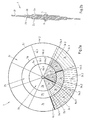
- Fig. 1 is a display device 1 for simplified representation of possible combinations of different surfaces, for example, in a sampling of a house or apartment shown.
- the display device 1 has a plurality, here three, relatively movable display means 2a, 2b and 2c, which are each divided into a plurality of segments 3a, 3b and 3c.
- the display means 2a is divided into eight segments 3a, the display means 2b in eight segments 3b and the display means 2c in eight segments 3c.
- the segments 3a, 3b and 3c are provided with different coatings, which are represented by corresponding hatching of the respective front three segments of the display means.
- the other segments are not hatched for reasons of clarity, but are still provided with different coatings.
- the coatings 3c.1, 3c.2 and 3c.3 of the outer display means 2c are different floor finishes.
- the coatings 3b.1, 3b.2 and 3b.3 of the central display means 2b represent colors of interior walls of a room.
- the coatings 3a.1, 3a.2 and 3a.3 finally represent coatings of exterior walls of a corresponding space.
- the individual display means 2a, 2b and 2c which are circular plastic discs, are different sizes, that is they have a different diameter. Furthermore, the disk-shaped display means are arranged on a common axis of rotation 4 concentric with each other and rotatable relative to each other about the axis of rotation 4. In this way, each segment of one of the display means may be matched with each segment of another of the display means.
- the individual display means are used in the case of Fig. 1 held rotatably by a bolt 8, so are rotatably connected to each other.
- the bolt 8 is detachable, so that the smaller display means, which are also provided on their back with segments and corresponding coatings (not visible in the selected representation) can be turned to increase the number of possible combinations on.
- the three display means 2a, 2b and 2c are arranged in the axial direction next to each other, so that they are arranged offset from one another in the radial direction.
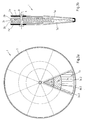
- FIGS. 2a ) and b) show a similar embodiment as Fig. 1 , but here, like Fig. 2b ), five display means of the type described above are provided, wherein the axially middle display means 2c has the largest diameter, the two adjacent display means 2b and 2b 'have a smaller diameter and the turn adjacent display means 2a and 2a' have an even smaller diameter.
- the display means 2c is divided on both sides into a plurality of segments, wherein the segments have different coatings.
- the display means 2a, 2b, 2b 'and 2a' are provided only on one side with segments.
- FIGS. 1 and 2a are also provided various markings.
- adjacent segments 3a, 3b and 3c of the same display means 2a, 2b and 2c are delimited from one another by an optical marking 6a.1, 6b.1 or 6c.1.
- adjacent segments 3a, 3b and 3c of different display means 2a, 2b and 2c are delimited from one another or from the environment by a haptic marking 6a.2, 6b.2 and 6c.2, respectively.
- particularly emphasized markings 6a.3, 6b.3 and 6c.3 are provided, which are likewise optical markings. Through these markings, a preferred optimum position of the display means is highlighted relative to each other, wherein in this optimal position, the respective combination of radially juxtaposed segments is tuned to each other in a particularly harmonious manner.
- FIGS. 3a ) and b) show an embodiment in which the display means 2a, 2a ', 2b, 2b' and 2c are arranged in the same manner as in FIGS FIGS. 2a ) and b).
- the display means are arranged here in a shell 7, which has a viewing window 7a or 7a 'on each side and as Fig. 3a ) shows on each side of the display device 1 exactly a combination of radially juxtaposed segments releases. The remaining segments are covered by the shell 7.
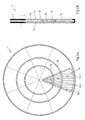
- FIGS. 4a ) and b) a display device 1, which also has a shell 7, which is provided on both sides with viewing windows 7a and 7a '.
- the two display means 2b and 2c are those in ring form, which are arranged in the radial direction in the same plane as the circular display means 2a and are provided on both sides with segments.
- the webs 7b are provided which are circumferentially arranged circumferentially. In the area of the viewing window 7a, the webs 7b may be interrupted.
- the display means are thus rotatably connected to each other, but indirectly, that is, without touching.
Landscapes
- Physics & Mathematics (AREA)
- General Physics & Mathematics (AREA)
- Engineering & Computer Science (AREA)
- Theoretical Computer Science (AREA)
- Displays For Variable Information Using Movable Means (AREA)
- Devices For Indicating Variable Information By Combining Individual Elements (AREA)
- Ultra Sonic Daignosis Equipment (AREA)
- Investigating Or Analyzing Materials By The Use Of Ultrasonic Waves (AREA)
- Measurement Of Velocity Or Position Using Acoustic Or Ultrasonic Waves (AREA)
Description
- Die Erfindung betrifft eine Anzeigevorrichtung zur vereinfachten Darstellung von Kombinationsmöglichkeiten unterschiedlicher Oberflächen mit mindestens zwei relativ zueinander beweglichen Anzeigemitteln, die jeweils in mehrere Segmente unterteilt sind, wobei mehrere der Segmente eines jeden Anzeigemittels mit unterschiedlichen Beschichtungen versehen sind, wobei die Anzeigemittel unterschiedlich groß sind, wobei die Anzeigemittel auf einer gemeinsamen Rotationsachse konzentrisch zueinander angeordnet sind und wobei die Anzeigemittel relativ zueinander um die Rotationsachse drehbar und miteinander verbunden sind. Eine solche Anzeigevorrichtung ist bekannt aus der
FR 1 517 049 A - Eine ähnliche Anzeigevorrichtung ist auch in der
US 3,798,798 A und derUS 4,112,594 A offenbart. - Aus dem Stand der Technik sind verschiedene Anzeigevorrichtungen bekannt, die dazu dienen, einem Benutzer, der beispielsweise seine Wohnung oder sein Haus in besonderer Weise farblich gestalten möchte, verschiedene Farben oder Farbkombinationen darzustellen. Auf diese Weise kann der Benutzer sich einfacher die einzelnen Farben vorstellen, mit denen später beispielsweise die Innen- oder Außenwände oder die Decken eines Raumes gestaltet werden sollen. Die genannten Anzeigemittel sind in einer Vielzahl von Varianten als sogenannte Farbfächer bekannt. Diese Farbfächer weisen, wie auch aus der
DE 71 15 544 U1 bekannt, eine Vielzahl von länglichen flachen Streifen aus Papier oder Kunststoff auf, die mit einer oder mehreren Segmenten mit unterschiedlichen Farbbeschichtungen versehen sind. - Der Benutzer hat die Möglichkeit, durch Anhalten eines solchermaßen farblich beschichteten Streifens an die zu streichende Wand eine seinen Wünschen entsprechende Farbe für den späteren Anstrich auszuwählen. Auch kann durch Nebeneinanderlegen mehrerer Farbstreifen mit unterschiedlichen Farben eine für den Benutzer gefällige Farbkombination bestimmt werden.
- Bei den zuvor beschriebenen Farbfächern können die einzelnen Anzeigemittel, das heißt die farblich beschichteten Papier-oder Kunststoffstreifen, an einem Ende beweglich miteinander verbunden sein, so dass die Anzeigemittel aufgefächert werden können. Es ist auch bekannt, den Farbfächer mit einer Abdeckung zu versehen, auf der verschiedene Haustypen dargestellt sind und bei der die Wände durch Sichtfenster ausgespart sind. Wird nun ein Anzeigemittel einer bestimmten Farbe unter die Abdeckung geführt, kann der Benutzer, da die Farbe durch das Sichtfenster nach außen hin sichtbar ist, erkennen, wie ein mit einer solchen Farbe angestrichenes Haus wirken kann.
- Problematisch bei diesen Farbfächern ist allerdings, dass die streifenförmigen Anzeigemittel oftmals eine Vielzahl von unterschiedlichen Farbsegmenten aufweisen und in dem Fall, dass alle streifenförmigen Anzeigemittel an einem Ende miteinander verbunden sind, nicht jedes Farbsegment des einen Streifens unmittelbar neben jedem Farbsegment eines anderen Streifens angeordnet werden kann. Möchte der Benutzer also einen Eindruck gewinnen, wie verschiedene Farben in Kombination miteinander wirken, so muss er entweder in Kauf nehmen, dass zwischen den beiden von ihm gewählten Farbsegmenten noch andere Farbsegmente sichtbar sind, die er dann von Hand abdecken müsste, oder der Benutzer muss die Anzeigevorrichtung, das heißt den Farbfächer, an den Enden der streifenförmigen Anzeigemittel auseinandernehmen und die Anzeigemittel vereinzeln, so dass er zwei vereinzelte Anzeigemittel nebeneinanderlegen kann. Beide Varianten sind wenig anwenderfreundlich und verlangen teilweise sogar eine erhöhte Vorstellungsgabe.
- Die eingangs beschriebene Anzeigevorrichtung mag die vorangehend beschriebenen Probleme zwar lösen, hat aber relativ große Abmessungen, um die vielen Kombinationsmöglichkeiten herstellen zu können.
- Es ist daher die Aufgabe der vorliegenden Erfindung, eine Anzeigevorrichtung zur vereinfachten Darstellung von Kombinationsmöglichkeiten unterschiedlicher Oberflächen zu schaffen, die möglichst viele Kombinationsmöglichkeiten unterschiedlicher Oberflächen darstellen kann und dennoch möglichst geringe Abmessungen aufweist.
- Die zuvor hergeleitete und aufgezeigte Aufgabe wird bei einer Anzeigevorrichtung zur vereinfachten Darstellung von Kombinationsmöglichkeiten unterschiedlicher Oberflächen mit mindestens zwei relativ zueinander beweglichen Anzeigemitteln, die jeweils in mehrere Segmente unterteilt sind, wobei mehrere der Segmente eines jeden Anzeigemittels mit unterschiedlichen Beschichtungen versehen sind, wobei die Anzeigemittel unterschiedlich groß sind, wobei die Anzeigemittel auf einer gemeinsamen Rotationsachse konzentrisch zueinander angeordnet sind und wobei die Anzeigemittel relativ zueinander um die Rotationsachse drehbar und miteinander verbunden sind, dadurch gelöst, dass mindestens ein Anzeigemittel beidseitig in jeweils mehrere Segmente unterteilt ist, wobei mehrere der Segmente mit unterschiedlichen Beschichtungen versehen sind.
Verbunden bedeutet in diesem Zusammenhang nicht zwangsläufig, dass sich die relativ zueinander drehbaren Anzeigemittel auch berühren müssen, also direkt miteinander verbunden sein müssen, sondern es ist auch eine indirekte Verbindung zwischen den Anzeigemitteln denkbar, beispielsweise durch eine Hülle oder einen Rahmen, die bzw. der die einzelnen, sich nicht berührenden Anzeigemittel hält. - Indem die Anzeigemittel relativ zueinander um eine Rotationsachse konzentrisch angeordnet und relativ zueinander drehbar sind und indem gleichzeitig die Anzeigemittel unterschiedlich groß sind, beispielsweise eine unterschiedlich große Oberfläche oder einen unterschiedlich großen Durchmesser haben, werden Flächen geschaffen, die um die jeweils kleinere Fläche herum drehbar sind. Werden die sichtbaren Flächen in Umfangsrichtung mit mehreren Segmenten mit jeweils unterschiedlichen Beschichtungen versehen, kann jede Beschichtung bzw. jedes Segment des einen Anzeigemittels durch Rotation des Anzeigemittels neben jede Beschichtung des jeweils benachbarten Anzeigemittels gebracht werden. Die Anwenderfreundlichkeit wird damit gegenüber dem Stand der Technik deutlich erhöht.
- Wie erwähnt ist mindestens ein Anzeigemittel beidseitig in jeweils mehrere Segmente unterteilt, wobei mehrere der Segmente mit unterschiedlichen Beschichtungen versehen sind. Mit anderen Worten sind auf jeder Seite des Anzeigemittels, beispielsweise auf jeder Seite einer kreisförmigen Scheibe, in Umfangsrichtung mehrere Segmente angeordnet. Ein beidseitiges Vorsehen von Segmenten unterschiedlicher Beschichtungen erhöht die Anzahl an darstellbaren Oberflächen und Kombinationsmöglichkeiten unterschiedlicher Oberflächen, ohne dass die Anzeigevorrichtung dadurch größere Abmessungen erhielte und unhandlicher würde. Dabei kann durchaus auch die im bestimmungsgemäß eingebauten Zustand verdeckte (nicht sichtbare) Seite mit Segmenten unterschiedlicher Beschichtungen versehen sein, wenn die Anzeigevorrichtung derart ausgebildet ist, dass einzelne oder alle Anzeigemittel gewendet werden können. Dadurch kann die Anzahl an Kombinationsmöglichkeiten weiter erhöht werden, bei gleichbleibenden Abmessungen der Anzeigevorrichtung.
- Im Folgenden werden nun verschiedene Ausgestaltungsmöglichkeiten der Anzeigevorrichtung und insbesondere der Anzeigemittel beschrieben. Dabei können sich die beschriebenen Ausgestaltungen auf mindestens eines der Anzeigemittel oder auf mehrere Anzeigemittel, vorzugsweise alle Anzeigemittel der Anzeigevorrichtung beziehen.
- Gemäß einer ersten Ausgestaltung ist mindestens ein Anzeigemittel scheibenförmig ausgebildet. Scheiben als Anzeigemittel haben den Vorteil, dass diese relativ flach sind und dadurch mehrere Anzeigemittel unterschiedlicher Größe nebeneinander angeordnet werden können, ohne dass dadurch die Anzeigevorrichtung unhandlich würde.
- Gemäß noch einer Ausgestaltung ist mindestens ein Anzeigemittel ringförmig oder kreisförmig ausgebildet. Insbesondere wenn es sich dabei um ringförmige oder kreisförmige Scheiben handelt, lassen sich dadurch die Anzeigemittel auf einfache Weise in Umfangsrichtung mit verschieden beschichteten Segmenten versehen und auch auf einfache Weise relativ zueinander um die zentrale Rotationsachse drehen.
- Gemäß wiederum einer weiteren Ausgestaltung hat die äußere Kante mindestens eines Anzeigemittels einen kreisförmigen Verlauf. Grundsätzlich wäre es aber auch denkbar, dass ein mehreckiger Verlauf der äußeren Kante vorgesehen ist, beispielsweise in dem Fall, dass das entsprechende Anzeigemittel aus einer Vielzahl von in Umfangsrichtung nebeneinander angeordneten gleichschenkligen Dreiecken besteht bzw. die Form einer solchen Anordnung hat.
- Gemäß noch einer Ausgestaltung besteht mindestens ein Anzeigemittel zumindest teilweise aus Papier, Pappe und/oder Kunststoff. Diese Materialien sind relativ leicht, was einer guten Handhabbarkeit der Anzeigevorrichtung zugute kommt. Außerdem können diese Materialien auf einfache Weise und dauerhaft beschichtet werden.
- Mindestens zwei der Anzeigemittel, bei denen es sich wie gesagt beispielsweise um scheibenförmige Ringe oder Kreise handeln kann, sind gemäß einer weiteren Ausgestaltung in radialer Richtung nebeneinander oder versetzt zueinander angeordnet. Insbesondere lassen sich Ringe unterschiedlicher Durchmesser in radialer Richtung ohne weiteres nebeneinander anordnen. Werden kreisförmige Scheiben verwendet, so können diese in axialer Richtung nebeneinander angeordnet werden und sind dann in radialer Richtung zwangsläufig versetzt zueinander. Insbesondere das Anordnen mehrerer Anzeigemittel in radialer Richtung nebeneinander führt zu einer besonders flachen Bauweise und damit besonders guten Anwenderfreundlichkeit der Anzeigevorrichtung.
- Entsprechend den zuvor definierten möglichen Formen, insbesondere der Kreisform oder Ringform, des jeweiligen Anzeigemittels sind gemäß noch einer weiteren Ausgestaltung die Segmente mindestens eines Anzeigemittels Kreissegmente oder Ringsegmente. Solche Segmente nutzen den vorhandenen Platz auf einem kreisförmigen oder ringförmigen Anzeigemittel für eine Beschichtung optimal aus. Grundsätzlich ist aber auch denkbar, die Segmente auf den Anzeigemitteln anders zu formen, beispielsweise durch Kreise oder Vielecke.
- Gemäß einer weiteren Ausgestaltung sind benachbarte Segmente desselben Anzeigemittels und/oder benachbarte Segmente unterschiedlicher Anzeigemittel durch eine Markierung voneinander abgegrenzt. Durch eine solche Markierung lassen sich für den Benutzer einerseits die unterschiedlichen Beschichtungen voneinander unterscheiden. Andererseits können erfindungsgemäß mehrere Beschichtungen, vorzugsweise alle Beschichtungen eines Anzeigemittels, eine Fußbodenoberfläche, eine Wandoberfläche, insbesondere Innen- oder Außenwandoberfläche, eine Deckenoberfläche, eine Möbeloberfläche, eine Tür- oder Türrahmenoberfläche, eine Fenster- oder Fensterrahmenoberfläche oder dergleichen darstellen. In diesem Fall kann der Benutzer durch eine entsprechende Markierung besser unterscheiden, welcher Oberfläche das jeweilige Segment und/oder das jeweilige Anzeigemittel zugeordnet ist.
- Jedes Segment mindestens eines Anzeigemittels weist gemäß einer weiteren Ausgestaltung eine andere Beschichtung auf. Wie gesagt können alle definierten Ausgestaltungen auch auf mehrere oder alle Anzeigemittel zutreffen, so dass vorzugsweise auch bei allen Anzeigemitteln jedes Segment eine andere Beschichtung aufweist. Auf diese Weise lassen sich eine Vielzahl von unterschiedlichen Oberflächen, beispielsweise von Fußboden-, Wand- oder Möbeloberflächen, auf engstem Raum darstellen.
- Gemäß noch einer weiteren Ausgestaltung unterscheiden sich die unterschiedlichen Beschichtungen in ihrer Farbe, ihrem Muster, ihrer Struktur (gemeint ist die dreidimensionale Oberflächenstruktur) und/oder ihrem Material. Beispielsweise ist es denkbar, dass einige Beschichtungen von einer Farbe gebildet werden, andere Beschichtungen von einer Wandoberfläche bzw. einem Wandbelag mit dreidimensionaler Struktur wie einer Tapete, einem Vlies, einem Putz oder dergleichen, und wiederum andere von einer Fußbodenoberfläche bzw. einem Fußbodenbelag wie einem Schichtstoff oder lediglich einem Dekorpapier, einem Teppich, einer Fliese oder dergleichen. Auch ist es denkbar, dass auf die einzelnen Anzeigemittel nur Darstellungen der jeweiligen Oberflächen, beispielsweise der Fußbodenoberfläche, aufgedruckt sind. Vorzugsweise weisen alle Segmente desselben Anzeigemittels eine Beschichtung, die einem bestimmten ersten Oberflächentyp zugeordnet ist, auf, während die Segmente eines anderen Anzeigemittels derselben Anzeigevorrichtung Beschichtungen eines anderen Oberflächentyps zeigen. Bei einer Anzeigevorrichtung mit mehreren, z.B. drei, kreis- und/oder ringförmigen Anzeigemittel wäre es beispielsweise denkbar, wenn die Segmente der beiden inneren bzw. kleineren Anzeigemittel Wandfarben darstellen, während die Segmente der äußeren bzw. größeren Scheibe Fußbodenbeläge oder Fußbodendekore darstellen.
- Da mit zunehmender Zahl von in Umfangsrichtung nebeneinander angeordneten Segmenten auch die Zahl von Kombinationsmöglichkeiten zunimmt, gleichzeitig auch nicht alle Kombinationen gleichermaßen harmonisch oder aus anderem Grunde gleichermaßen sinnvoll sind, ist gemäß einer weiteren Ausgestaltung mindestens eine Kombination von radial nebeneinander angeordneten Segmenten durch eine Markierung hervorgehoben. So kann sich auf einem oder mehreren der Anzeigemittel, vorzugsweise auf allen Anzeigemitteln, bei zumindest einem Segment eine Markierung befinden, die zulässt, dass der Benutzer die verschiedenen Anzeigemittel relativ zueinander so verdreht, dass die Markierungen in Übereinstimmung gebracht werden können. Sind die Markierungen in Übereinstimmung, kann auf diese Weise eine bevorzugte Optimalstellung der Anzeigevorrichtung eingestellt werden, in der beispielsweise eine oder vorzugsweise alle radialen Kombinationen in besonderer Weise, beispielsweise auf besonders harmonische Weise, aufeinander abgestimmt sind. In dieser Optimalstellung sind beispielsweise bestimmte Fußbodendekore immer bestimmten Wandfarben zugeordnet.
- Die zuvor erwähnten Markierungen, das heißt sowohl die Markierungen, die benachbarte Segmente voneinander abgrenzen, als auch die Markierungen, die eine bestimmte Kombination hervorheben, können optische Markierungen und/oder haptische, also durch Berühren erfahrbare Markierungen, sein.
- Gemäß noch einer weiteren Ausgestaltung sind die Anzeigemittel in einer Hülle, einem Rahmen oder einem Gestell angeordnet, mit insbesondere mindestens einem Sichtfenster. Eine Hülle dient einerseits dem Schutz der Anzeigemittel und der Beschichtung, andererseits kann die Hülle in Kombination mit einem Sichtfenster bestimmte Bereiche der Anzeigemittel bzw. der Anzeigevorrichtung abdecken und andere Bereiche freigeben. Diese Funktionen kann auch besagter Rahmen oder besagtes Gestell erfüllen. So ist es denkbar, dass durch das Sichtfenster nur eine einzige Kombination von radial nebeneinander angeordneten Segmenten und damit Beschichtungen nach außen hin sichtbar ist, wohingegen alle anderen Kombinationen durch die Hülle, den Rahmen oder das Gestell abgedeckt sind. Oder es kann eine bestimmte Kombination durch Hülle, Rahmen bzw. Gestell eingerahmt und dadurch optisch und/oder haptisch hervorgehoben werden, während dennoch ein Teil der übrigen Anzeigemittel sichtbar bleiben kann. Bei einer Anzeigevorrichtung, die ein oder mehrere beidseitig bedruckte Anzeigemittel aufweist, die also auf beiden Seiten verschiedene Kombinationen von Oberflächen darstellen kann, können Hülle, Rahmen bzw. Gestell auch so geformt sein, dass auf jeder Seite der Anzeigevorrichtung mindestens jeweils ein Sichtfenster vorgesehen ist, das insbesondere nur jeweils eine einzige Kombination freigibt oder hervorhebt und vorzugsweise den Rest der Anzeigemittel abdeckt.
- Die Hülle kann außerdem die Funktion eines Trägers für die Anzeigemittel haben, insbesondere wenn es sich bei den Anzeigemitteln zumindest teilweise um Ringsegmente handelt, die in radialer Richtung in derselben Ebene nebeneinander angeordnet sind. Da die Anzeigemittel relativ zueinander drehbar sein müssen, dient die Hülle auch als Führung und verhindert, dass sich einige Anzeigemittel überlappen können. Gemäß einer entsprechenden weiteren Ausgestaltung werden die Anzeigemittel daher von der Hülle drehbar gehalten. Grundsätzlich ist es aber auch denkbar, die Anzeigemittel von einem Bolzen drehbar halten zu lassen, der vorzugsweise koaxial zur Rotationsachse verläuft. Die Anzeigemittel werden dann von diesem Bolzen zusammengehalten und können um diesen herum relativ zueinander gedreht werden. Schließlich ist auch eine Kombination von Bolzen und Hülle denkbar.
- Es gibt nun eine Vielzahl von Möglichkeiten, die erfindungsgemäße Anzeigevorrichtung auszugestalten und weiterzubilden. Hierzu wird beispielsweise verwiesen einerseits auf die dem Patentanspruch 1 nachgeordneten Patentansprüche, andererseits auf die Beschreibung von Ausführungsbeispielen in Verbindung mit der Zeichnung. In der Zeichnung zeigt:
- Fig. 1
- eine perspektivische Ansicht eines Ausführungsbeispiels einer Anzeigevorrichtung,
- Fig. 2a) und b)
- eine Draufsicht und Schnittansicht eines weiteren Ausführungsbeispiels einer Anzeigevorrichtung,
- Fig. 3a) und b)
- eine Draufsicht und Schnittansicht noch eines weiteren Ausführungsbeispiels einer Anzeigevorrichtung und
- Fig. 4a) und b)
- eine Draufsicht und Schnittansicht noch eines weiteren Ausführungsbeispiels einer Anzeigevorrichtung.
- In
Fig. 1 ist eine Anzeigevorrichtung 1 zur vereinfachten Darstellung von Kombinationsmöglichkeiten unterschiedlicher Oberflächen, beispielsweise bei einer Bemusterung eines Hauses oder einer Wohnung, dargestellt. Die Anzeigevorrichtung 1 weist mehrere, hier drei, relativ zueinander bewegliche Anzeigemittel 2a, 2b und 2c auf, die jeweils in mehrere Segmente 3a, 3b und 3c unterteilt sind.
Das Anzeigemittel 2a ist dabei in acht Segmente 3a, das Anzeigemittel 2b in acht Segmente 3b und das Anzeigemittel 2c in acht Segmente 3c unterteilt. Bei jedem Anzeigemittel 2a, 2b bzw. 2c sind die Segmente 3a, 3b bzw. 3c mit unterschiedlichen Beschichtungen versehen, die durch entsprechende Schraffuren der jeweils vorderen drei Segmente der Anzeigemittel dargestellt sind. Die übrigen Segmente sind aus Gründen der Übersichtlichkeit nicht schraffiert, sind aber dennoch mit unterschiedlichen Beschichtungen versehen. - Bei den Beschichtungen 3c.1, 3c.2 und 3c.3 des äußeren Anzeigemittels 2c handelt es sich um verschiedene Fußbodendekore. Die Beschichtungen 3b.1, 3b.2 und 3b.3 des mittleren Anzeigemittels 2b stellen Farben von Innenwänden eines Raumes dar. Die Beschichtungen 3a.1, 3a.2 und 3a.3 stellen schließlich Beschichtungen von Außenwänden eines entsprechenden Raumes dar.
- Die einzelnen Anzeigemittel 2a, 2b und 2c, bei denen es sich um kreisförmige Kunststoffscheiben handelt, sind unterschiedlich groß, das heißt sie haben einen unterschiedlichen Durchmesser. Ferner sind die scheibenförmigen Anzeigemittel auf einer gemeinsamen Rotationsachse 4 konzentrisch zueinander angeordnet und relativ zueinander um die Rotationsachse 4 drehbar. Auf diese Weise kann jedes Segment eines der Anzeigemittel mit jedem Segment eines anderen der Anzeigemittel in Übereinstimmung gebracht werden.
- Die einzelnen Anzeigemittel werden im Falle der
Fig. 1 von einem Bolzen 8 drehbar gehalten, sind also drehbar miteinander verbunden. Dabei ist der Bolzen 8 lösbar, so dass die kleineren Anzeigemittel, die auch auf ihrer Rückseite mit Segmenten und entsprechenden Beschichtungen versehen sind (in gewählter Darstellung nicht sichtbar) gewendet werden können, um die Anzahl an Kombinationsmöglichkeiten weiter zu erhöhen. - Bei der Anzeigevorrichtung in
Fig. 1 sind die drei Anzeigemittel 2a, 2b und 2c in axialer Richtung nebeneinander angeordnet, so dass sie in radialer Richtung versetzt zueinander angeordnet sind. - Die
Figuren 2a ) und b) zeigen ein ähnliches Ausführungsbeispiel wieFig. 1 , wobei hier jedoch, wieFig. 2b ) zeigt, fünf Anzeigemittel der zuvor beschriebenen Art vorgesehen sind, wobei das in axialer Richtung mittlere Anzeigemittel 2c den größten Durchmesser hat, die beiden dazu benachbarten Anzeigemittel 2b bzw. 2b' einen kleineren Durchmesser haben und die dazu wiederum benachbarten Anzeigemittel 2a bzw. 2a' einen noch kleineren Durchmesser haben. Das Anzeigemittel 2c ist dabei beidseitig in jeweils mehrere Segmente unterteilt, wobei die Segmente unterschiedliche Beschichtungen aufweisen. Die Anzeigemittel 2a, 2b, 2b' und 2a' sind nur einseitig mit Segmenten versehen. - Bei den Ausführungsbeispielen in den
Figuren 1 und2a ) sind ferner verschiedene Markierungen vorgesehen. Zum einen sind benachbarte Segmente 3a, 3b bzw. 3c desselben Anzeigemittels 2a, 2b bzw. 2c durch eine optische Markierung 6a.1, 6b.1 bzw. 6c.1 voneinander abgegrenzt. Außerdem sind benachbarte Segmente 3a, 3b bzw. 3c unterschiedlicher Anzeigemittel 2a, 2b bzw. 2c durch eine haptische Markierung 6a.2, 6b.2 bzw. 6c.2 voneinander bzw. gegenüber der Umgebung abgegrenzt. Schließlich sind noch besonders hervorgehobene Markierungen 6a.3, 6b.3 und 6c.3 vorgesehen, bei denen es sich ebenfalls um optische Markierungen handelt. Durch diese Markierungen wird eine bevorzugte Optimalstellung der Anzeigemittel relativ zueinander hervorgehoben, wobei in dieser Optimalstellung die jeweilige Kombination von radial nebeneinander angeordneten Segmenten in besonders harmonischer Weise aufeinander abgestimmt ist. - Die
Figuren 3a ) und b) zeigen ein Ausführungsbeispiel, bei dem die Anzeigemittel 2a, 2a', 2b, 2b' und 2c in derselben Weise angeordnet sind, wie in denFiguren 2a ) und b). Zusätzlich sind die Anzeigemittel hier jedoch in einer Hülle 7 angeordnet, die zu jeder Seite ein Sichtfenster 7a bzw. 7a' aufweist und wieFig. 3a ) zeigt, auf jeder Seite der Anzeigevorrichtung 1 genau eine Kombination von radial nebeneinander angeordneten Segmenten freigibt. Die übrigen Segmente sind durch die Hülle 7 abgedeckt. - Schließlich zeigen die
Figuren 4a ) und b) eine Anzeigevorrichtung 1, die ebenfalls eine Hülle 7 aufweist, die beidseitig mit Sichtfenstern 7a und 7a' versehen ist. Jedoch handelt es sich hier bei den beiden Anzeigemitteln 2b und 2c um solche in Ringform, die in radialer Richtung in derselben Ebene wie das kreisförmige Anzeigemittel 2a angeordnet sind und beidseitig mit Segmenten versehen sind. Zur Führung der einzelnen Anzeigemittel in der Hülle sind Stege 7b vorgesehen, die in Umfangsrichtung umlaufend angeordnet sind. Im Bereich der Sichtfenster 7a können die Stege 7b unterbrochen sein. Auch in diesem Ausführungsbeispiel sind die Anzeigemittel also drehbar miteinander verbunden, jedoch indirekt, das heißt ohne sich dabei zu berühren.
Claims (14)
- Anzeigevorrichtung (1) zur vereinfachten Darstellung von Kombinationsmöglichkeiten unterschiedlicher Oberflächen- mit mindestens zwei relativ zueinander beweglichen Anzeigemitteln (2a,2a',2b,2b',2c), die jeweils in mehrere Segmente (3a,3b,3c) unterteilt sind, wobei mehrere der Segmente (3a,3b,3c) eines jeden Anzeigemittels (2a,2a',2b,2b',2c) mit unterschiedlichen Beschichtungen (3a.1,3a.2,3a.3,3b.1,3b.2,3b.3,3c.1, 3c.2,3c.3) versehen sind,- wobei die Anzeigemittel (2a,2a',2b,2b',2c) unterschiedlich groß sind,- wobei die Anzeigemittel (2a,2a',2b,2b',2c) auf einer gemeinsamen Rotationsachse (4) konzentrisch zueinander angeordnet sind und- wobei die Anzeigemittel (2a,2a',2b,2b',2c) relativ zueinander um die Rotationsachse (4) drehbar und miteinander verbunden sind,
dadurch gekennzeichnet,- dass mindestens ein Anzeigemittel (2a,2a',2b,2b',2c) beidseitig in jeweils mehrere Segmente (3a,3b,3c) unterteilt ist, wobei mehrere der Segmente (3a,3b,3c) mit unterschiedlichen Beschichtungen (3a.1,3a.2,3a.3,3b.1,3b.2,3b.3,3c.1,3c.2,3c.3) versehen sind. - Anzeigevorrichtung (1) nach Anspruch 1, dadurch gekennzeichnet, dass mindestens ein Anzeigemittel (2a,2a',2b,2b',2c) scheibenförmig und/oder ring- oder kreisförmig ausgebildet ist.
- Anzeigemittelvorrichtung (1) nach einem der vorangehenden Ansprüche, dadurch gekennzeichnet, dass die äußere Kante (5a,5b,5c) mindestens eines Anzeigemittels (2a,2a', 2b,2b',2c) einen kreisförmigen oder mehreckigen Verlauf hat.
- Anzeigevorrichtung (1) nach einem der vorangehenden Ansprüche, dadurch gekennzeichnet, dass mindestens ein Anzeigemittel (2a,2a',2b,2b',2c) zumindest teilweise aus Papier, Pappe und/oder Kunststoff besteht.
- Anzeigevorrichtung (1) nach einem der vorangehenden Ansprüche, dadurch gekennzeichnet, dass mindestens zwei der Anzeigemittel (2a,2a',2b,2b',2c) in radialer Richtung nebeneinander oder versetzt zueinander angeordnet sind.
- Anzeigevorrichtung (1) nach einem der vorangehenden Ansprüche, dadurch gekennzeichnet, dass die Segmente (3a,3b,3c) mindestens eines Anzeigemittels (2a,2a', 2b,2b',2c) Kreissegmente (3a) oder Ringsegmente (3b,3c) sind.
- Anzeigevorrichtung (1) nach einem der vorangehenden Ansprüche, dadurch gekennzeichnet, dass benachbarte Segmente (3a,3b,3c) desselben Anzeigemittels (2a,2a', 2b,2b',2c) und/oder benachbarte Segmente (3a,3b,3c) unterschiedlicher Anzeigemittel (2a,2a',2b,2b',2c) durch eine Markierung (6a.1,6a.2,6b.1,6b.2,6c.1,6c.2), insbesondere eine optische Markierung (6a.1,6b.1,6c.1) und/oder eine haptische Markierung (6a.2,6b.2,6c.2), voneinander abgegrenzt sind.
- Anzeigevorrichtung (1) nach einem der vorangehenden Ansprüche, dadurch gekennzeichnet, dass jedes Segment (3a,3b,3c) mindestens eines Anzeigemittels (2a,2a', 2b,2b',2c) eine andere Beschichtung (3a.1,3a.2,3a.3, 3b.1,3b.2,3b.3,3c.1,3c.2,3c.3) aufweist.
- Anzeigevorrichtung (1) nach einem der vorangehenden Ansprüche, dadurch gekennzeichnet, dass die unterschiedlichen Beschichtungen (3a.1,3a.2,3a.3,3b.1, 3b.2,3b.3,3c.1,3c.2,3c.3) sich in ihrer Farbe, ihrem Muster, ihrer Struktur und/oder ihrem Material unterscheiden.
- Anzeigevorrichtung (1) nach einem der vorangehenden Ansprüche, dadurch gekennzeichnet, dass mehrere Beschichtungen (3a.1,3a.2,3a.3,3b.1,3b.2,3b.3, 3c.1,3c.2,3c.3), vorzugsweise alle Beschichtungen (3a.1,3a.2,3a.3,3b.1,3b.2,3b.3,3c.1,3c.2,3c.3) eines Anzeigemittel (2a,2a',2b,2b',2c), eine Fußbodenoberfläche, eine Wandoberfläche, insbesondere Innen- oder Außenwandoberfläche, eine Deckenoberfläche, eine Möbeloberfläche, eine Tür- oder Türrahmenoberfläche oder eine Fenster- oder Fensterrahmenoberfläche darstellen.
- Anzeigevorrichtung (1) nach einem der vorangehenden Ansprüche, dadurch gekennzeichnet, dass sie derart ausgebildet ist, dass einzelne oder alle Anzeigemittel (2a,2a',2b,2b',2c) gewendet werden können.
- Anzeigevorrichtung (1) nach einem der vorangehenden Ansprüche, dadurch gekennzeichnet, dass mindestens eine Kombination von radial nebeneinander angeordneten Segmenten (3a,3b,3c) durch eine Markierung (6a.3,6b.3,6c.3) hervorgehoben ist.
- Anzeigevorrichtung (1) nach einem der vorangehenden Ansprüche, dadurch gekennzeichnet, dass die Anzeigemittel (2a,2a',2b,2b',2c) in einer Hülle (7), einem Rahmen oder einem Gestell angeordnet sind, mit insbesondere mindestens einem Sichtfenster (7a,7a').
- Anzeigevorrichtung (1) nach einem der vorangehenden Ansprüche, dadurch gekennzeichnet, dass die Anzeigemittel (2a,2a',2b,2b',2c) von einem Bolzen (8) oder von der Hülle (7), dem Rahmen oder dem Gestell drehbar gehalten werden.
Priority Applications (1)
| Application Number | Priority Date | Filing Date | Title |
|---|---|---|---|
| PL10163233T PL2298574T3 (pl) | 2009-09-02 | 2010-05-19 | Urządzenie do prezentacji do ułatwionego przedstawienia możliwości kombinacji różnych powierzchni |
Applications Claiming Priority (1)
| Application Number | Priority Date | Filing Date | Title |
|---|---|---|---|
| DE202009011864U DE202009011864U1 (de) | 2009-09-02 | 2009-09-02 | Anzeigevorrichtung zur vereinfachten Darstellung von Kombinationsmöglichkeiten unterschiedlicher Oberflächen |
Publications (2)
| Publication Number | Publication Date |
|---|---|
| EP2298574A1 EP2298574A1 (de) | 2011-03-23 |
| EP2298574B1 true EP2298574B1 (de) | 2011-11-23 |
Family
ID=41429104
Family Applications (1)
| Application Number | Title | Priority Date | Filing Date |
|---|---|---|---|
| EP10163233A Not-in-force EP2298574B1 (de) | 2009-09-02 | 2010-05-19 | Anzeigevorrichtung zur vereinfachten Darstellung von Kombinationsmöglichkeiten unterschiedlicher Oberflächen |
Country Status (4)
| Country | Link |
|---|---|
| EP (1) | EP2298574B1 (de) |
| AT (1) | ATE534532T1 (de) |
| DE (1) | DE202009011864U1 (de) |
| PL (1) | PL2298574T3 (de) |
Families Citing this family (1)
| Publication number | Priority date | Publication date | Assignee | Title |
|---|---|---|---|---|
| CN113741056B (zh) * | 2021-07-22 | 2024-12-03 | 亿信科技发展有限公司 | 三维显示系统 |
Family Cites Families (5)
| Publication number | Priority date | Publication date | Assignee | Title |
|---|---|---|---|---|
| DE950232C (de) * | 1953-10-15 | 1956-10-04 | Alfred Rat | Farbmustertafel zur Auswahl der Farbe beim Faerben von Haaren |
| FR1517049A (fr) * | 1967-01-26 | 1968-03-15 | Appareil pour la présentation d'une juxtaposition de couleurs | |
| DE7115544U (de) | 1971-04-19 | 1971-08-12 | Deutsche Amphibolin Werke V Murjahn R | Farbfaecher als hilfsmittel fuer malerarbeiten aller art |
| US3798798A (en) * | 1973-03-30 | 1974-03-26 | F Shore | Frame-selection picture frame simulator |
| US4112594A (en) * | 1977-04-28 | 1978-09-12 | Impastato Leona R | Color coordinating implement |
-
2009
- 2009-09-02 DE DE202009011864U patent/DE202009011864U1/de not_active Expired - Lifetime
-
2010
- 2010-05-19 EP EP10163233A patent/EP2298574B1/de not_active Not-in-force
- 2010-05-19 PL PL10163233T patent/PL2298574T3/pl unknown
- 2010-05-19 AT AT10163233T patent/ATE534532T1/de active
Also Published As
| Publication number | Publication date |
|---|---|
| ATE534532T1 (de) | 2011-12-15 |
| EP2298574A1 (de) | 2011-03-23 |
| DE202009011864U1 (de) | 2009-12-24 |
| PL2298574T3 (pl) | 2012-04-30 |
Similar Documents
| Publication | Publication Date | Title |
|---|---|---|
| EP2298574A1 (de) | Anzeigevorrichtung zur vereinfachten Darstellung von Kombinationsmöglichkeiten unterschiedlicher Oberflächen | |
| AT11506U1 (de) | Anzeigevorrichtung zur vereinfachten darstellung von kombinationsmöglichkeiten unterschiedlicher oberflächen | |
| EP3087868B1 (de) | Möbelplatte | |
| DE3402967A1 (de) | Akustische wand | |
| DE19613330C2 (de) | Wurfpfeilzielscheibenvorrichtung mit unabhängig gelagertem, doppeltem Zentrumssegment | |
| DE3633941A1 (de) | Fliesensatz zur abdeckung von bodenflaechen | |
| DE102017214175A1 (de) | Nachrüstbare Verblendung für Möbelstücke | |
| EP3023085B1 (de) | Sarg | |
| DE2808611A1 (de) | Schutzschirm fuer duscheinrichtungen | |
| DE102009021502B4 (de) | Vorrichtung zum Halten von mindestens zwei länglichen Gegenständen, insbesondere Stiften | |
| DE102009060400B4 (de) | Tischkalender | |
| EP0649616A1 (de) | Zylinderförmiger Rundschrank | |
| AT13409U1 (de) | Vorrichtung zur Ermittlung eines Ausgangsparameterwerts | |
| EP3400845A1 (de) | Vorrichtung zum präsentieren von farbmustern | |
| AT14746U1 (de) | Aufsatz-Türfüllung und diese umfassende Tür | |
| DE7017343U (de) | Programmsteuergeraet. | |
| DE4130478A1 (de) | Flaechenelemente fuer raumkoerper und ihre verbindungen | |
| EP0014321B1 (de) | Sanitäre Ausstattungsarmatur | |
| DE29903802U1 (de) | Schutzabdeckung für elektrische Installationsgeräte | |
| DE102012011751B4 (de) | Raffstore und Haspeleinheit dafür | |
| DE2161367C2 (de) | ||
| DE102007034165B3 (de) | Schutz- und Betrachtungsvorrichtung für Kunstwerke | |
| DE7122173U (de) | Gurtscheibe fur Rolladen | |
| DE19548884A1 (de) | Haltevorrichtung | |
| DE29520490U1 (de) | Haltevorrichtung |
Legal Events
| Date | Code | Title | Description |
|---|---|---|---|
| PUAI | Public reference made under article 153(3) epc to a published international application that has entered the european phase |
Free format text: ORIGINAL CODE: 0009012 |
|
| AK | Designated contracting states |
Kind code of ref document: A1 Designated state(s): AL AT BE BG CH CY CZ DE DK EE ES FI FR GB GR HR HU IE IS IT LI LT LU LV MC MK MT NL NO PL PT RO SE SI SK SM TR |
|
| AX | Request for extension of the european patent |
Extension state: BA ME RS |
|
| 17P | Request for examination filed |
Effective date: 20110427 |
|
| GRAP | Despatch of communication of intention to grant a patent |
Free format text: ORIGINAL CODE: EPIDOSNIGR1 |
|
| RIC1 | Information provided on ipc code assigned before grant |
Ipc: B44D 3/00 20060101AFI20110622BHEP |
|
| GRAS | Grant fee paid |
Free format text: ORIGINAL CODE: EPIDOSNIGR3 |
|
| GRAA | (expected) grant |
Free format text: ORIGINAL CODE: 0009210 |
|
| AK | Designated contracting states |
Kind code of ref document: B1 Designated state(s): AL AT BE BG CH CY CZ DE DK EE ES FI FR GB GR HR HU IE IS IT LI LT LU LV MC MK MT NL NO PL PT RO SE SI SK SM TR |
|
| REG | Reference to a national code |
Ref country code: GB Ref legal event code: FG4D Free format text: NOT ENGLISH |
|
| REG | Reference to a national code |
Ref country code: CH Ref legal event code: NV Representative=s name: TROESCH SCHEIDEGGER WERNER AG Ref country code: CH Ref legal event code: EP |
|
| REG | Reference to a national code |
Ref country code: IE Ref legal event code: FG4D Free format text: LANGUAGE OF EP DOCUMENT: GERMAN |
|
| REG | Reference to a national code |
Ref country code: NL Ref legal event code: T3 |
|
| REG | Reference to a national code |
Ref country code: DE Ref legal event code: R096 Ref document number: 502010000239 Country of ref document: DE Effective date: 20120119 |
|
| LTIE | Lt: invalidation of european patent or patent extension |
Effective date: 20111123 |
|
| PG25 | Lapsed in a contracting state [announced via postgrant information from national office to epo] |
Ref country code: LT Free format text: LAPSE BECAUSE OF FAILURE TO SUBMIT A TRANSLATION OF THE DESCRIPTION OR TO PAY THE FEE WITHIN THE PRESCRIBED TIME-LIMIT Effective date: 20111123 Ref country code: NO Free format text: LAPSE BECAUSE OF FAILURE TO SUBMIT A TRANSLATION OF THE DESCRIPTION OR TO PAY THE FEE WITHIN THE PRESCRIBED TIME-LIMIT Effective date: 20120223 Ref country code: IS Free format text: LAPSE BECAUSE OF FAILURE TO SUBMIT A TRANSLATION OF THE DESCRIPTION OR TO PAY THE FEE WITHIN THE PRESCRIBED TIME-LIMIT Effective date: 20120323 |
|
| REG | Reference to a national code |
Ref country code: PL Ref legal event code: T3 |
|
| PG25 | Lapsed in a contracting state [announced via postgrant information from national office to epo] |
Ref country code: SE Free format text: LAPSE BECAUSE OF FAILURE TO SUBMIT A TRANSLATION OF THE DESCRIPTION OR TO PAY THE FEE WITHIN THE PRESCRIBED TIME-LIMIT Effective date: 20111123 Ref country code: HR Free format text: LAPSE BECAUSE OF FAILURE TO SUBMIT A TRANSLATION OF THE DESCRIPTION OR TO PAY THE FEE WITHIN THE PRESCRIBED TIME-LIMIT Effective date: 20111123 Ref country code: SI Free format text: LAPSE BECAUSE OF FAILURE TO SUBMIT A TRANSLATION OF THE DESCRIPTION OR TO PAY THE FEE WITHIN THE PRESCRIBED TIME-LIMIT Effective date: 20111123 Ref country code: LV Free format text: LAPSE BECAUSE OF FAILURE TO SUBMIT A TRANSLATION OF THE DESCRIPTION OR TO PAY THE FEE WITHIN THE PRESCRIBED TIME-LIMIT Effective date: 20111123 Ref country code: PT Free format text: LAPSE BECAUSE OF FAILURE TO SUBMIT A TRANSLATION OF THE DESCRIPTION OR TO PAY THE FEE WITHIN THE PRESCRIBED TIME-LIMIT Effective date: 20120323 Ref country code: GR Free format text: LAPSE BECAUSE OF FAILURE TO SUBMIT A TRANSLATION OF THE DESCRIPTION OR TO PAY THE FEE WITHIN THE PRESCRIBED TIME-LIMIT Effective date: 20120224 |
|
| REG | Reference to a national code |
Ref country code: IE Ref legal event code: FD4D |
|
| PG25 | Lapsed in a contracting state [announced via postgrant information from national office to epo] |
Ref country code: CY Free format text: LAPSE BECAUSE OF FAILURE TO SUBMIT A TRANSLATION OF THE DESCRIPTION OR TO PAY THE FEE WITHIN THE PRESCRIBED TIME-LIMIT Effective date: 20111123 |
|
| PG25 | Lapsed in a contracting state [announced via postgrant information from national office to epo] |
Ref country code: DK Free format text: LAPSE BECAUSE OF FAILURE TO SUBMIT A TRANSLATION OF THE DESCRIPTION OR TO PAY THE FEE WITHIN THE PRESCRIBED TIME-LIMIT Effective date: 20111123 Ref country code: SK Free format text: LAPSE BECAUSE OF FAILURE TO SUBMIT A TRANSLATION OF THE DESCRIPTION OR TO PAY THE FEE WITHIN THE PRESCRIBED TIME-LIMIT Effective date: 20111123 Ref country code: IE Free format text: LAPSE BECAUSE OF FAILURE TO SUBMIT A TRANSLATION OF THE DESCRIPTION OR TO PAY THE FEE WITHIN THE PRESCRIBED TIME-LIMIT Effective date: 20111123 Ref country code: EE Free format text: LAPSE BECAUSE OF FAILURE TO SUBMIT A TRANSLATION OF THE DESCRIPTION OR TO PAY THE FEE WITHIN THE PRESCRIBED TIME-LIMIT Effective date: 20111123 Ref country code: CZ Free format text: LAPSE BECAUSE OF FAILURE TO SUBMIT A TRANSLATION OF THE DESCRIPTION OR TO PAY THE FEE WITHIN THE PRESCRIBED TIME-LIMIT Effective date: 20111123 Ref country code: BG Free format text: LAPSE BECAUSE OF FAILURE TO SUBMIT A TRANSLATION OF THE DESCRIPTION OR TO PAY THE FEE WITHIN THE PRESCRIBED TIME-LIMIT Effective date: 20120223 |
|
| PG25 | Lapsed in a contracting state [announced via postgrant information from national office to epo] |
Ref country code: IT Free format text: LAPSE BECAUSE OF FAILURE TO SUBMIT A TRANSLATION OF THE DESCRIPTION OR TO PAY THE FEE WITHIN THE PRESCRIBED TIME-LIMIT Effective date: 20111123 Ref country code: RO Free format text: LAPSE BECAUSE OF FAILURE TO SUBMIT A TRANSLATION OF THE DESCRIPTION OR TO PAY THE FEE WITHIN THE PRESCRIBED TIME-LIMIT Effective date: 20111123 |
|
| PLBE | No opposition filed within time limit |
Free format text: ORIGINAL CODE: 0009261 |
|
| STAA | Information on the status of an ep patent application or granted ep patent |
Free format text: STATUS: NO OPPOSITION FILED WITHIN TIME LIMIT |
|
| 26N | No opposition filed |
Effective date: 20120824 |
|
| BERE | Be: lapsed |
Owner name: FRITZ EGGER GMBH & CO. OG Effective date: 20120531 |
|
| REG | Reference to a national code |
Ref country code: DE Ref legal event code: R097 Ref document number: 502010000239 Country of ref document: DE Effective date: 20120824 |
|
| PG25 | Lapsed in a contracting state [announced via postgrant information from national office to epo] |
Ref country code: MC Free format text: LAPSE BECAUSE OF NON-PAYMENT OF DUE FEES Effective date: 20120531 |
|
| PG25 | Lapsed in a contracting state [announced via postgrant information from national office to epo] |
Ref country code: BE Free format text: LAPSE BECAUSE OF NON-PAYMENT OF DUE FEES Effective date: 20120531 Ref country code: MK Free format text: LAPSE BECAUSE OF FAILURE TO SUBMIT A TRANSLATION OF THE DESCRIPTION OR TO PAY THE FEE WITHIN THE PRESCRIBED TIME-LIMIT Effective date: 20111123 |
|
| PG25 | Lapsed in a contracting state [announced via postgrant information from national office to epo] |
Ref country code: ES Free format text: LAPSE BECAUSE OF FAILURE TO SUBMIT A TRANSLATION OF THE DESCRIPTION OR TO PAY THE FEE WITHIN THE PRESCRIBED TIME-LIMIT Effective date: 20120305 |
|
| PG25 | Lapsed in a contracting state [announced via postgrant information from national office to epo] |
Ref country code: MT Free format text: LAPSE BECAUSE OF FAILURE TO SUBMIT A TRANSLATION OF THE DESCRIPTION OR TO PAY THE FEE WITHIN THE PRESCRIBED TIME-LIMIT Effective date: 20111123 |
|
| PG25 | Lapsed in a contracting state [announced via postgrant information from national office to epo] |
Ref country code: AL Free format text: LAPSE BECAUSE OF FAILURE TO SUBMIT A TRANSLATION OF THE DESCRIPTION OR TO PAY THE FEE WITHIN THE PRESCRIBED TIME-LIMIT Effective date: 20111123 |
|
| PG25 | Lapsed in a contracting state [announced via postgrant information from national office to epo] |
Ref country code: SM Free format text: LAPSE BECAUSE OF FAILURE TO SUBMIT A TRANSLATION OF THE DESCRIPTION OR TO PAY THE FEE WITHIN THE PRESCRIBED TIME-LIMIT Effective date: 20111123 Ref country code: LU Free format text: LAPSE BECAUSE OF NON-PAYMENT OF DUE FEES Effective date: 20120519 |
|
| PG25 | Lapsed in a contracting state [announced via postgrant information from national office to epo] |
Ref country code: HU Free format text: LAPSE BECAUSE OF FAILURE TO SUBMIT A TRANSLATION OF THE DESCRIPTION OR TO PAY THE FEE WITHIN THE PRESCRIBED TIME-LIMIT Effective date: 20100519 |
|
| REG | Reference to a national code |
Ref country code: FR Ref legal event code: PLFP Year of fee payment: 7 |
|
| REG | Reference to a national code |
Ref country code: FR Ref legal event code: PLFP Year of fee payment: 8 |
|
| REG | Reference to a national code |
Ref country code: FR Ref legal event code: PLFP Year of fee payment: 9 |
|
| PGFP | Annual fee paid to national office [announced via postgrant information from national office to epo] |
Ref country code: DE Payment date: 20210517 Year of fee payment: 12 Ref country code: NL Payment date: 20210519 Year of fee payment: 12 Ref country code: FR Payment date: 20210518 Year of fee payment: 12 Ref country code: FI Payment date: 20210519 Year of fee payment: 12 |
|
| PGFP | Annual fee paid to national office [announced via postgrant information from national office to epo] |
Ref country code: AT Payment date: 20210519 Year of fee payment: 12 Ref country code: TR Payment date: 20210408 Year of fee payment: 12 Ref country code: PL Payment date: 20210408 Year of fee payment: 12 Ref country code: CH Payment date: 20210517 Year of fee payment: 12 Ref country code: GB Payment date: 20210518 Year of fee payment: 12 |
|
| REG | Reference to a national code |
Ref country code: DE Ref legal event code: R119 Ref document number: 502010000239 Country of ref document: DE |
|
| REG | Reference to a national code |
Ref country code: CH Ref legal event code: PL |
|
| REG | Reference to a national code |
Ref country code: NL Ref legal event code: MM Effective date: 20220601 |
|
| REG | Reference to a national code |
Ref country code: AT Ref legal event code: MM01 Ref document number: 534532 Country of ref document: AT Kind code of ref document: T Effective date: 20220519 |
|
| GBPC | Gb: european patent ceased through non-payment of renewal fee |
Effective date: 20220519 |
|
| PG25 | Lapsed in a contracting state [announced via postgrant information from national office to epo] |
Ref country code: LI Free format text: LAPSE BECAUSE OF NON-PAYMENT OF DUE FEES Effective date: 20220531 Ref country code: FI Free format text: LAPSE BECAUSE OF NON-PAYMENT OF DUE FEES Effective date: 20220519 Ref country code: CH Free format text: LAPSE BECAUSE OF NON-PAYMENT OF DUE FEES Effective date: 20220531 Ref country code: AT Free format text: LAPSE BECAUSE OF NON-PAYMENT OF DUE FEES Effective date: 20220519 |
|
| PG25 | Lapsed in a contracting state [announced via postgrant information from national office to epo] |
Ref country code: FR Free format text: LAPSE BECAUSE OF NON-PAYMENT OF DUE FEES Effective date: 20220531 |
|
| PG25 | Lapsed in a contracting state [announced via postgrant information from national office to epo] |
Ref country code: GB Free format text: LAPSE BECAUSE OF NON-PAYMENT OF DUE FEES Effective date: 20220519 Ref country code: DE Free format text: LAPSE BECAUSE OF NON-PAYMENT OF DUE FEES Effective date: 20221201 |
|
| PG25 | Lapsed in a contracting state [announced via postgrant information from national office to epo] |
Ref country code: NL Free format text: LAPSE BECAUSE OF NON-PAYMENT OF DUE FEES Effective date: 20220601 |
|
| PG25 | Lapsed in a contracting state [announced via postgrant information from national office to epo] |
Ref country code: PL Free format text: LAPSE BECAUSE OF NON-PAYMENT OF DUE FEES Effective date: 20220519 |
|
| PG25 | Lapsed in a contracting state [announced via postgrant information from national office to epo] |
Ref country code: TR Free format text: LAPSE BECAUSE OF NON-PAYMENT OF DUE FEES Effective date: 20220519 |