EP2298593B1 - Siège pliable - Google Patents
Siège pliable Download PDFInfo
- Publication number
- EP2298593B1 EP2298593B1 EP09758159.9A EP09758159A EP2298593B1 EP 2298593 B1 EP2298593 B1 EP 2298593B1 EP 09758159 A EP09758159 A EP 09758159A EP 2298593 B1 EP2298593 B1 EP 2298593B1
- Authority
- EP
- European Patent Office
- Prior art keywords
- section
- supporting bracket
- seat
- vehicle
- passive
- Prior art date
- Legal status (The legal status is an assumption and is not a legal conclusion. Google has not performed a legal analysis and makes no representation as to the accuracy of the status listed.)
- Active
Links
Images



Classifications
-
- B—PERFORMING OPERATIONS; TRANSPORTING
- B60—VEHICLES IN GENERAL
- B60N—SEATS SPECIALLY ADAPTED FOR VEHICLES; VEHICLE PASSENGER ACCOMMODATION NOT OTHERWISE PROVIDED FOR
- B60N2/00—Seats specially adapted for vehicles; Arrangement or mounting of seats in vehicles
- B60N2/24—Seats specially adapted for vehicles; Arrangement or mounting of seats in vehicles for particular purposes or particular vehicles
- B60N2/30—Non-dismountable or dismountable seats storable in a non-use position, e.g. foldable spare seats
- B60N2/3002—Non-dismountable or dismountable seats storable in a non-use position, e.g. foldable spare seats back-rest movements
- B60N2/3004—Non-dismountable or dismountable seats storable in a non-use position, e.g. foldable spare seats back-rest movements by rotation only
- B60N2/3009—Non-dismountable or dismountable seats storable in a non-use position, e.g. foldable spare seats back-rest movements by rotation only about transversal axis
- B60N2/3011—Non-dismountable or dismountable seats storable in a non-use position, e.g. foldable spare seats back-rest movements by rotation only about transversal axis the back-rest being hinged on the cushion, e.g. "portefeuille movement"
-
- B—PERFORMING OPERATIONS; TRANSPORTING
- B60—VEHICLES IN GENERAL
- B60N—SEATS SPECIALLY ADAPTED FOR VEHICLES; VEHICLE PASSENGER ACCOMMODATION NOT OTHERWISE PROVIDED FOR
- B60N2/00—Seats specially adapted for vehicles; Arrangement or mounting of seats in vehicles
- B60N2/02—Seats specially adapted for vehicles; Arrangement or mounting of seats in vehicles the seat or part thereof being movable, e.g. adjustable
- B60N2/20—Seats specially adapted for vehicles; Arrangement or mounting of seats in vehicles the seat or part thereof being movable, e.g. adjustable the back-rest being tiltable, e.g. to permit easy access
-
- B—PERFORMING OPERATIONS; TRANSPORTING
- B60—VEHICLES IN GENERAL
- B60N—SEATS SPECIALLY ADAPTED FOR VEHICLES; VEHICLE PASSENGER ACCOMMODATION NOT OTHERWISE PROVIDED FOR
- B60N2/00—Seats specially adapted for vehicles; Arrangement or mounting of seats in vehicles
- B60N2/24—Seats specially adapted for vehicles; Arrangement or mounting of seats in vehicles for particular purposes or particular vehicles
- B60N2/30—Non-dismountable or dismountable seats storable in a non-use position, e.g. foldable spare seats
- B60N2/3038—Cushion movements
- B60N2/304—Cushion movements by rotation only
- B60N2/3045—Cushion movements by rotation only about transversal axis
- B60N2/305—Cushion movements by rotation only about transversal axis the cushion being hinged on the vehicle frame
-
- B—PERFORMING OPERATIONS; TRANSPORTING
- B60—VEHICLES IN GENERAL
- B60N—SEATS SPECIALLY ADAPTED FOR VEHICLES; VEHICLE PASSENGER ACCOMMODATION NOT OTHERWISE PROVIDED FOR
- B60N2/00—Seats specially adapted for vehicles; Arrangement or mounting of seats in vehicles
- B60N2/24—Seats specially adapted for vehicles; Arrangement or mounting of seats in vehicles for particular purposes or particular vehicles
- B60N2/42—Seats specially adapted for vehicles; Arrangement or mounting of seats in vehicles for particular purposes or particular vehicles the seat constructed to protect the occupant from the effect of abnormal g-forces, e.g. crash or safety seats
- B60N2/4207—Seats specially adapted for vehicles; Arrangement or mounting of seats in vehicles for particular purposes or particular vehicles the seat constructed to protect the occupant from the effect of abnormal g-forces, e.g. crash or safety seats characterised by the direction of the g-forces
- B60N2/4214—Seats specially adapted for vehicles; Arrangement or mounting of seats in vehicles for particular purposes or particular vehicles the seat constructed to protect the occupant from the effect of abnormal g-forces, e.g. crash or safety seats characterised by the direction of the g-forces longitudinal
-
- B—PERFORMING OPERATIONS; TRANSPORTING
- B60—VEHICLES IN GENERAL
- B60N—SEATS SPECIALLY ADAPTED FOR VEHICLES; VEHICLE PASSENGER ACCOMMODATION NOT OTHERWISE PROVIDED FOR
- B60N2/00—Seats specially adapted for vehicles; Arrangement or mounting of seats in vehicles
- B60N2/24—Seats specially adapted for vehicles; Arrangement or mounting of seats in vehicles for particular purposes or particular vehicles
- B60N2/42—Seats specially adapted for vehicles; Arrangement or mounting of seats in vehicles for particular purposes or particular vehicles the seat constructed to protect the occupant from the effect of abnormal g-forces, e.g. crash or safety seats
- B60N2/427—Seats or parts thereof displaced during a crash
- B60N2/42709—Seats or parts thereof displaced during a crash involving residual deformation or fracture of the structure
-
- B—PERFORMING OPERATIONS; TRANSPORTING
- B60—VEHICLES IN GENERAL
- B60N—SEATS SPECIALLY ADAPTED FOR VEHICLES; VEHICLE PASSENGER ACCOMMODATION NOT OTHERWISE PROVIDED FOR
- B60N2/00—Seats specially adapted for vehicles; Arrangement or mounting of seats in vehicles
- B60N2/24—Seats specially adapted for vehicles; Arrangement or mounting of seats in vehicles for particular purposes or particular vehicles
- B60N2/42—Seats specially adapted for vehicles; Arrangement or mounting of seats in vehicles for particular purposes or particular vehicles the seat constructed to protect the occupant from the effect of abnormal g-forces, e.g. crash or safety seats
- B60N2/427—Seats or parts thereof displaced during a crash
- B60N2/42727—Seats or parts thereof displaced during a crash involving substantially rigid displacement
- B60N2/42745—Seats or parts thereof displaced during a crash involving substantially rigid displacement of the back-rest
Definitions
- the present invention relates to a folding type seat.
- a seat has been adopted having a seat back provided with side portions onto which a pair of right and left side frames are provided, the side frames being provided with weakened portions, respectively (see, for instance, JP2001186957 ).
- the weakened portions include inclined portions each bent in a triangular shape in cross section. When a load is imparted to the seat at a vehicle front or a vehicle rear, the inclined portions are caused to bent and deform thereby absorbing impact energy.
- the inclined portions are located on the side frames at front ends thereof in the vicinity of a surface of the seat back. Accordingly, as a vehicle occupant sits on the seat, the inclined portions project toward the vehicle occupant, causing an issue of the vehicle occupant having a sense of incongruity with degradation in sitting comfort.
- the present invention has been completed with the above issue in mind and has an object to provide a folding type seat that can keep excellent sitting comfort without causing any sense of incongruity when a vehicle occupant sits on the seat.
- the present invention provides a folding type seat comprising: a seat frame having a seat cushion frame mounted on a seat back frame to be pivotable on the seat cushion frame; a body supporting bracket fixed to the seat cushion frame and supporting a body section that forms a reclining mechanism; and a passive section supporting bracket fixed to the seat cushion frame and supporting a passive section that forms the reclining mechanism.
- the body supporting bracket and the passive section supporting bracket are located inward of external surfaces of the seat cushion bracket and the seat back at positions spaced by a predetermined distance therefrom.
- At least one of the body supporting bracket and the passive section supporting bracket includes an impact absorbing section for absorbing impact energy imparted to the seat frame in a fore and aft direction of a vehicle.
- the body supporting bracket and the passive section supporting bracket are located inward of the external surfaces of the seat cushion and the seat back at the positions spaced by the predetermined distance therefrom.
- the body supporting bracket and/or the passive section supporting bracket include the impact absorbing section. Accordingly, when the vehicle occupant sits on the seat, no impact absorbing section gives a sense of incongruity to the vehicle occupant, thereby enabling excellent sitting comfort to be maintained.
- the impact absorbing section deforms at a position spaced from the vehicle occupant by a predetermined distance, thereby absorbing impact energy. This results in improvement in efficiency of absorbing impact energy.
- FIG. 1 is a perspective view of a seat frame forming a folding type seat of a first embodiment
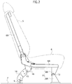
- FIG. 2 is a side view of the folding type seat shown in FIG. 1
- FIG. 3 is a cross-sectional view taken on line X-X of FIG. 1
- FIG. 4 is an enlarged side view of essential parts in an area mounted with a passive supporting bracket for supporting a passive section forming a reclining mechanism shown in FIG. 1
- FIG. 5 is a cross-sectional view showing how a body supporting bracket is caused to deform rearward of a vehicle due to a load applied to the seat frame at a front of the vehicle for thereby absorbing impact energy
- FIG. 6 is a cross-sectional view showing how the passive supporting bracket is caused to deform rearward of the vehicle due to the load applied to the seat frame at the front of the vehicle for thereby absorbing impact energy.
- FIG. 1 shows only seat cushions and seat frames with seat backs being omitted for clarifying structures of the seat frames.
- an arrow "FR" indicates a vehicle front; an arrow "RR” a vehicle rear; an arrow "X” a vehicle width direction; and an arrow “Z” a vehicle height.
- the folding type seat 1 of the present embodiment includes a rear seat formed in a three seater configuration and takes a structure including a single-seater folding type seat 2 and a two-seater folding type seat 3.
- both of these seats take the same structures and, hence, the present invention will be described with reference to the two-seater folding type seat 3 as one example.
- the two-seater folding type seat 3 includes: a seat frame 6 on which a seat cushion 4 and a seat back 5 are mounted; front leg sections 8 pivotally mounted on the seat frame 6 at the front of the vehicle and fixedly secured to a vehicle floor 7; rear leg sections 10 pivotally mounted on the seat frame 6 at the rear of the vehicle and engageable with or disengageable from a striker 9 fixedly secured to the vehicle floor 7; and a reclining mechanism 11 allowing the seat back 5 to be foldable with respect to the seat cushion 4.
- the seat frame 6 includes a seat cushion frame 6A composed of a plurality of steel pipes connected in combination and allowing the seat cushion 4 to be mounted thereon, and a seat back frame 6B on which the seat back 5 is mounted.
- the seat back frame 6B is structured to be pivotable (in folding capability) with respect to the seat cushion frame 6A in the fore and aft direction of the vehicle upon operating a strap 12 (see FIG. 1 ) protruding outside of an upper end of the seat back 5 connected to the reclining mechanism, described later.
- the front leg sections 8 include floor-side legs 8A fixedly secured to the vehicle floor 7, and frame-side legs 8B fixedly secured to the seat cushion frame 6A to be pivotable about pivot shafts 13, respectively.
- the front leg sections 8 are spaced from each other with a predetermined distance in the vehicle width direction in a pair on right and left sides.
- the rear leg sections 10 include locking devices (not shown) causing the rear leg sections 10 to be engageable with and disengageable from the striker 9 and are structured to disengage from the striker 9 when a strap belt 14 is pulled.
- the rear leg sections 10 have leading ends provided with fulcrum pivot shafts 15, respectively, which are pivotally mounted on brackets 16 of the seat cushion frame 6A. In the illustrated embodiment, the rear leg sections 10 are located at two positions spaced from each other with a predetermined distance in the vehicle width direction.
- the reclining mechanism 11 includes a body section 17, mounted on the seat back frame 6B at a central area thereof in the vehicle width direction, and a passive section 19 mounted on the seat back frame 6B on a side thereof and interconnected to the body section 19 via a rod 18.
- An unlocking mechanism 20 is connected to the body section 17.
- the unlocking mechanism 20 is connected to the strap 12 for canceling a locked state of the seat back frame 6B with respect to the seat cushion frame 6A.
- the seat cushion frame 6A is provided with a body section supporting bracket 21, supporting the body section 17 of the reclining mechanism 11, and a passive section supporting bracket 22 supporting the passive section 19.
- the body section supporting bracket 21 is formed in a nearly L-shape configuration, when viewed from the front, with a fixed section 21A fixed on the seat cushion frame 6A by means of fastening means, such as bolts and nuts or the like, and a connecting section 21B vertically standing upright from the fixed section 21A.
- the connecting section 21B is bent in a nearly L-shape as a whole when viewed from the side.
- the connecting section 21B has a rearward portion that is bent upward with respect to a forward portion at a boundary of the central portion in the fore and aft direction.
- the bend section 23 When a load is imparted to the seat frame 6 in the fore and aft direction of the vehicle, the bend section 23 is caused to extend and deform in deployment in the fore and aft direction, enabling impact energy to be absorbed.
- the bend section 23 of the body supporting bracket 21 plays a role as an impact absorbing section 30.
- the body section supporting bracket 21 is located inward (downward and rearward) of the external surfaces the seat cushion 4 and the seat back 5 at a position spaced therefrom by a predetermined distance. That is, the connecting section 21B of the body section supporting bracket 21 has a vehicular forward leading edge that is located at a position downward and rearward of the external surfaces of the seat cushion 4 and the seat back 5 to be spaced by a predetermined distance therefrom. Accordingly, when a vehicle occupant sits on the seat, no body section supporting bracket 21 causes the vehicle occupant to have a sense of incongruity due to the body section supporting bracket 21 located at a position distanced from the body of the vehicle occupant.
- the impact absorbing section 30 is arranged to cause the body section supporting bracket 21 to deform so as to fold rearward of the vehicle with a fulcrum at a main pipe 24, mounted on the seat cushion frame 6A at a rear end thereof and extending along the vehicle width direction, such that impact energy is absorbed.
- the bend section 23 of the body section supporting bracket 21 is caused to deform (particularly in plastic deformation) so as to extend in deployment toward the vehicle rear with the fulcrum at the main pipe 24, thereby absorbing impact energy. This causes the body section supporting bracket 21 not to deform in the vehicle width direction like the related art but to deform rearward of the vehicle.
- the passive section supporting bracket 22 is fixedly secured to the sides of the seat cushion frame 6A by means of fastening means such as bolts and nuts or the like.
- the passive section supporting bracket 22 is formed in a nearly L-shaped flat-plate configuration, when viewed from the side, and fixedly secured to the sides of the seat cushion frame with a plate-thickness direction aligned in a mounting direction.
- the bend section 25 is set to the impact absorbing section 30 that absorbs impact energy upon extending and deforming in deployment in the fore and aft direction of the vehicle due to the load imparted to the seat frame in the fore and aft direction of the vehicle.
- the load when the load is imparted to the seat frame 6 in the fore and aft direction of the vehicle, the load is transferred to the passive section supporting bracket 22 formed in the L-shaped configuration. That is, the bend section 25 is so arranged as to extend and deform (particularly in plastic deformation) in deployment in the fore and aft direction of the vehicle such that impact energy is absorbed.
- the bend section 25, playing as a role as the impact absorbing section 30, allows the passive section supporting bracket 22 to fold deforming rearward of the vehicle with the fulcrum at the main pipe 24 provided on the seat cushion frame 6A at the rear of the vehicle to extend in the vehicle width direction, thereby absorbing impact energy.
- the bend section 25 of the passive section supporting bracket 22 is caused to extend rearward of the vehicle with the fulcrum at the main pipe 24 in response to the load imparted to the seat frame 6 at, for instance, the front of the vehicle, thereby absorbing impact energy.
- This causes the passive section supporting bracket 22, like the body section supporting bracket 21, not to deform in the vehicle width direction as experienced in the related art but to deform rearward of the vehicle.
- the passive section supporting bracket 22 is located at a position inward (downward and rearward) of the external surfaces of the seat cushion 4 and the seat back 5 to be spaced by a predetermined distance. That is, the passive section supporting bracket 22 is located at the position downward and rearward of the external surfaces of the seat cushion 4 and the seat back 5 to be spaced by the predetermined distance. Accordingly, under a situation where the vehicle occupant sits on the seat, the passive section supporting bracket 22 is placed apart from the body of the vehicle occupant and the vehicle occupant has no sense of incongruity resulting from the passive section supporting bracket 22.
- the passive section supporting bracket 22 is formed with a cutout portion 26 for facilitating the deformation of the bend section 25 playing a role as the impact absorbing section 30.
- the cutout portion 26 is cut out in a circular arc shape toward the main pipe 24 when viewed from the side.
- the cutout portion 26 may be formed in a position close proximity to the bend section 23 of the body section supporting bracket 21.
- the bend sections 23 and 25, formed on the body section supporting bracket 21 and the passive section supporting bracket 22, respectively, are located between mount points between the respective brackets and the seat cushion frame 6A and mount points between the body section 17, forming the respective brackets and the reclining mechanism 11, and the passive section 19. That is, the bend section 23 is located between the mount point, at which the body section supporting bracket 21 is mounted on the seat cushion frame 6A, and the mount point at which the body section 17 is mounted onto the bracket. In addition, the bend section 25 is located between the mount point, at which the passive section supporting bracket 22 is mounted on the seat cushion frame 6A, and the mount point at which the passive section 19 is mounted on the bracket.
- bend sections 23 and 25 of the respective brackets 21 and 22 may be set to lie at inclined angles such that the body section supporting bracket 21 and the passive section supporting bracket 22 bear the nearly same amounts of deformations.
- the seat back frame 6B When the load, oriented rearward of the vehicle, is imparted to the seat frame 6 at the front of the vehicle, the seat back frame 6B, made foldable with respect to the seat cushion frame 6A, is pulled rearward of the vehicle.
- the body section supporting bracket 21 allows the bend section 23 to extend in deformation from an initial state, indicated by a chain double-dashed line, so as to deploy rearward of the vehicle with the fulcrum at the main pipe 24 as indicated by a solid line shown in FIG. 5 . If the external force is large, further, the connecting section 21B is caused to deform and lift upward with respect to the fixed section 21A of the body section supporting bracket 21.
- the bend section 25 is caused to deform from an initial state, as shown by a two-dot chain line in FIG. 6 , deploying rearward of the vehicle with a fulcrum on the main pipe 24 in response to an external force applied from the seat back frame 6B similarly pulled rearward of the vehicle as indicated by a solid line.
- the bend section 25 is formed with the cutout portion 26, which allows deformation to easily occur such that deformation is further enhanced thereby facilitating the bracket to deform rearward of the vehicle.
- none of the body section supporting bracket 21 and the passive section supporting bracket 22 is caused to deform so as to protrude toward the vehicle occupant during a collision of the vehicle and these component parts are caused to deform rearward of the vehicle for thereby absorbing impact energy. Further, when the load is imparted from the rear of the vehicle to the seat frame 6 toward the front of the vehicle, the body section supporting bracket 21 and the passive section supporting bracket 22 cause the respective bend sections 23 and 25 to deform in response to an external force, pushing the seat back frame 6B in the vehicle front, such that impact energy is absorbed
- the body section supporting bracket 21 and the passive section supporting bracket 22 are located inward (downward and rearward) of the external surfaces of the seat cushion 4 or the seat back 5 in positions spaced therefrom by a predetermined distance. During a normal mode, therefore, a space can be ensured between the vehicle occupant and the seat frame 6, enabling the vehicle occupant to enhance excellent sitting comfort and performance.
- the body section supporting bracket 21 and/or the passive section supporting bracket 22 are caused to deform at a position distanced from the vehicle occupant such that impact energy is absorbed, resulting in improved efficiency of absorbing impact energy.
- the deformations of the brackets 21 and 22 are not limited to the deformations in the fore and aft direction of the vehicle but involve those occurring in a vehicle width direction.
- the load imparted to the seat frame 6 at the front or the rear of the vehicle causes the bend sections 23 and 25 of the body section supporting bracket 21 and the passive section supporting bracket 22, supporting the body section 17 or the passive section 19 of the reclining mechanism 11, to deform in the fore and aft direction of the vehicle for thereby absorbing impact energy. Accordingly, none of the brackets 21 and 22 is caused to deform in protrusion toward the vehicle occupant and, hence, a space can be enhanced between the vehicle occupant and the seat frame 6 even when an impact load is imparted.
- the load imparted on the seat frame 6 causes the bend sections 23 and 25 of the body section supporting bracket 21 and the passive section supporting bracket 22 to deform for absorbing impact energy. This enables energy to be absorbed with a simplified structure.
- the bend section 25 of the passive section supporting bracket 22 is formed with the cutout portion 26 and the cutout portion 26 facilitates the deformation of the bend section 25.
- the bend sections 23 and 25 are provided between the mount position for the respective brackets 21 and 22 and the seat cushion 6A and the mount position for the respective brackets 21 and 22, the body section 17 and the passive section 19, thereby enabling the brackets to be miniaturized.
- the passive section supporting bracket 22 is formed in the flat-plate configuration and fixed to the side of the seat cushion frame with the plate-thickness direction aligned in the mounting direction.
- the bracket 22 can be placed between adjacent seats and no need arises for wastefully widening a space between the seats 2 and 3.
- FIG. 7 is a cross-sectional view, showing a vicinity of a body section supporting bracket of the second embodiment, which corresponds to FIG. 3 related to the first embodiment.
- FIG. 8 is a side view, showing a vicinity of a passive section supporting bracket of the second embodiment, which corresponds to FIG. 4 related to the first embodiment.
- FIG. 9 is a side view taken on line Y-Y of FIG. 8 .
- the body section supporting bracket 121 and the passive section supporting bracket 122 are provided with convexed sections 131 and 141 in the form of curved sections 130 and 140, which are set to be the impact absorbing section 30.
- the body section supporting bracket 121 has a nearly L-shaped configuration formed with a fixed section 121A, fixedly secured to the seat cushion frame 6A by means of fastening means such as bolts and nuts, and a connecting section 121B vertically standing upright from the fixed section 121A.
- the curved section 130 is formed in the vicinity of the bend section 23 and protruding leftward of the vehicle.
- the passive section supporting bracket 122 is fixedly secured to the side of the seat cushion frame 6A by means of fastening means such as bolts and nuts.
- the passive section supporting bracket 122 is formed in a nearly L-shaped flat-plate configuration and fixedly secured to the side of the seat cushion frame 6A by means of fastening means such as bolts and nuts with a plate-thickness direction aligned on the mounting direction.
- the bend section 25 has a curved section 140 formed of a convexed section 141 protruding rightward of the vehicle in the vicinity of the bend section 25.
- the curve section 140 is formed on the passive section supporting bracket 122 in an area close proximity to the bend section 25 and has a circular arc shape in cross section to play a role as the convexed portion 141 protruding rightward of the vehicle.
- the curved section 140 protrudes rightward of the vehicle toward the outside thereof in the width direction of the seat and, as will be apparent from FIG. 1 , has the convexed shape formed in a direction distanced from the vehicle occupant sitting on the seat.
- the curved section 140 (convexed portion 141) longitudinally extends in a flat shape to move in deformation in the vehicle width direction as shown in FIG. 9 .
- This causes the passive section supporting bracket 122 to deform from a shape, indicated by a solid line, to a shape indicated by a two-dot chain line.
- the convexed section 131 and the curved section 130 have the same cross-sectional shapes as those of the convexed section and the curved section 140 shown in FIG. 9 .
- the curved section 130 (convexed section 131) and the curved section 140 (convexed section 141) extend in a way to expand forward and obliquely upward at an axis center of the main pipe 24.
- the body section supporting bracket 121 and the passive section supporting bracket 122 are located inward (downward and rearward) from the external surfaces of the seat cushion 4 and the seat back 5 at positions spaced by a predetermined distance. During a normal mode, therefore, a space can be ensured between the vehicle occupant and the seat frame 6. Thus, the body section supporting bracket 121 and the passive section supporting bracket 122 allow the vehicle occupant to have excellent sitting comfort with no sense of incongruity.
- the body section supporting bracket 121 and/or the passive section supporting bracket 122 are caused to deform absorbing impact energy at a position spaced from the vehicle occupant, resulting in improved efficiency of absorbing impact energy.
- the body section supporting bracket 121 and the passive section supporting bracket 122 are provided with the convexed portions 131 and 141, formed in the convexed shapes when viewed from the front, which are set to be the impact absorbing member 30. Therefore, when the load is applied to the seat back frame 6B in the fore and aft direction of the vehicle, the convexed portions 131 and 141 (curved portions 130 and 140) extend to deform in the flat shape and in the vehicle width direction, thereby enabling impact energy to be efficiently absorbed.
- the convexed portions 131 and 141 each having a margin of extension, allows the convexed portions 131 and 141 to extend in deformation, enabling impact energy to be absorbed at further increased efficiency.
- the convexed portions 131 and 141 are formed in the curved sections 130 and 140 in circular arc cross sections.
- the curved sections 130 and 140 extend in deformation, thereby enabling impact energy to be absorbed at extremely high efficiency.
Landscapes
- Engineering & Computer Science (AREA)
- Aviation & Aerospace Engineering (AREA)
- Transportation (AREA)
- Mechanical Engineering (AREA)
- Seats For Vehicles (AREA)
Claims (6)
- Siège de type pliable comprenant :un châssis de siège (6) composé d'un châssis de coussin de siège (6A) et d'un châssis de dossier de siège (6B) ;un étrier de support de corps (21) supportant une section de corps (17), formant un mécanisme d'inclinaison (11), et fixé au châssis de coussin de siège (6A) ; etun étrier de support de section passive (22) supportant une section passive (19), formant le mécanisme d'inclinaison (11), et fixé au châssis de coussin de siège (6A) ; etau moins l'un de l'étrier de support de corps (21) et de l'étrier de support de section passive (22) comprenant une section d'absorption d'impact (30) prévue dans une position sous le mécanisme d'inclinaison (11) pour absorber l'énergie d'impact appliquée au châssis de siège (6) dans une direction longitudinale d'un véhicule,caractérisé parl'étrier de support de corps (21) et l'étrier de support de section passive (22) étant positionnés à l'intérieur de surfaces externes du coussin de siège (4) et du dossier de siège (5) par des distances d'espacement prédéterminées,dans lequel la section d'absorption d'impact (30) comprend une section incurvée (23, 25) prévue sur le au moins un de l'étrier de support de corps (21) et de l'étrier de support de section passive (22) et incurvée dans une configuration presque en forme de L lorsque vue de côté ; etdans lequel la section incurvée (23, 25) est amenée à se déformer de manière à s'étendre en déploiement en réponse à la charge imprimée au châssis de siège (6) dans la direction longitudinale du véhicule.
- Siège de type pliable selon la revendication 1, dans lequel :
la section d'absorption d'impact (30) comprend une section découpée (26). - Siège de type pliable selon l'une quelconque des revendications 1 à 2, dans lequel :
la section d'absorption d'impact (30) comprend une section rendue convexe (131,141) prévue sur le au moins un de l'étrier de support de corps (121) et de l'étrier de support de section passive (122), et faisant saillie dans une direction de largeur de véhicule lorsque vue à partir de l'avant. - Siège de type pliable selon la revendication 3, dans lequel :
la section rendue convexe (131, 141) comprend une section incurvée (130, 140) qui est incurvée dans une configuration d'arc presque circulaire lorsque vue à partir de l'avant. - Siège de type pliable selon l'une quelconque des revendications 1 à 4, dans lequel :
la section d'absorption d'impact (30) est prévue entre un point de montage pour les étriers respectifs (21,22) et le châssis de coussin de siège (6A) et un point de montage pour les étriers respectifs (21,22), la section de corps (17) et la section passive (19). - Siège de type pliable selon l'une quelconque des revendications 1 à 5, dans lequel :
l'étrier de support de section passive (22) a une forme de plaque plate et est fixé à un côté du châssis de coussin de siège (6A) avec une direction d'épaisseur de plaque alignée sur une direction de montage.
Applications Claiming Priority (2)
| Application Number | Priority Date | Filing Date | Title |
|---|---|---|---|
| JP2008149335 | 2008-06-06 | ||
| PCT/JP2009/056278 WO2009147892A1 (fr) | 2008-06-06 | 2009-03-27 | Siège pliable |
Publications (3)
| Publication Number | Publication Date |
|---|---|
| EP2298593A1 EP2298593A1 (fr) | 2011-03-23 |
| EP2298593A4 EP2298593A4 (fr) | 2015-05-20 |
| EP2298593B1 true EP2298593B1 (fr) | 2018-05-09 |
Family
ID=41397971
Family Applications (1)
| Application Number | Title | Priority Date | Filing Date |
|---|---|---|---|
| EP09758159.9A Active EP2298593B1 (fr) | 2008-06-06 | 2009-03-27 | Siège pliable |
Country Status (5)
| Country | Link |
|---|---|
| US (1) | US8845019B2 (fr) |
| EP (1) | EP2298593B1 (fr) |
| JP (1) | JP5338813B2 (fr) |
| CN (1) | CN102056764B (fr) |
| WO (1) | WO2009147892A1 (fr) |
Families Citing this family (31)
| Publication number | Priority date | Publication date | Assignee | Title |
|---|---|---|---|---|
| JP5488275B2 (ja) | 2010-07-09 | 2014-05-14 | トヨタ紡織株式会社 | 車両用シートフレームの支持構造 |
| JP5662171B2 (ja) * | 2011-01-07 | 2015-01-28 | テイ・エス テック株式会社 | 格納式リアシート |
| JP5847529B2 (ja) * | 2011-10-14 | 2016-01-27 | トヨタ紡織株式会社 | シートバックフレーム |
| CN103661048B (zh) * | 2012-08-31 | 2017-08-25 | 重庆长安汽车股份有限公司 | 一种汽车后排座椅靠背骨架 |
| JP6007722B2 (ja) * | 2012-10-19 | 2016-10-12 | スズキ株式会社 | 車両用シートバック構造 |
| JP5895810B2 (ja) * | 2012-10-23 | 2016-03-30 | トヨタ紡織株式会社 | 車両用シート |
| JP6166643B2 (ja) * | 2013-01-23 | 2017-07-19 | 株式会社デルタツーリング | 車両用シート |
| FR3012385B1 (fr) * | 2013-10-30 | 2015-12-18 | Antolin Grupo Ing Sa | Siege escamotable anti deversement |
| FR3016862B1 (fr) * | 2014-01-24 | 2016-01-22 | Airbus Helicopters | Banquette pour aeronef comportant des baquets montes individuellement basculants vers le bas et a l'arriere de la banquette en cas de forte deceleration de l'aeronef |
| US10227023B2 (en) * | 2015-03-31 | 2019-03-12 | Safran Seats Usa Llc | Energy absorbing brackets for passenger seats |
| CA2936917C (fr) | 2015-07-23 | 2018-05-22 | Dorel Juvenile Group, Inc. | Dispositif de securite pour enfant dote d'un mecanisme de gestion d'energie |
| WO2017018491A1 (fr) | 2015-07-29 | 2017-02-02 | テイ・エス テック株式会社 | Châssis de siège de véhicule |
| EP3333012B1 (fr) * | 2015-08-04 | 2021-04-14 | TS Tech Co., Ltd. | Cadre de siège pour véhicule |
| CN105109373A (zh) * | 2015-08-27 | 2015-12-02 | 富卓汽车内饰(安徽)有限公司 | 汽车后排座椅固定结构 |
| CN105059160A (zh) * | 2015-08-27 | 2015-11-18 | 富卓汽车内饰(安徽)有限公司 | 汽车后排座椅 |
| DE102017208381A1 (de) | 2016-05-27 | 2017-11-30 | Ford Global Technologies, Llc | Befestigungshalter für konsole |
| DE102017200646B4 (de) * | 2017-01-17 | 2023-03-23 | Lear Corporation | Fahrzeug-Sitzanordnung und Easy-Entry-Löse-System |
| JP2018199383A (ja) * | 2017-05-26 | 2018-12-20 | トヨタ紡織株式会社 | 乗物用シートのバックフレームの取付構造 |
| US10525853B2 (en) * | 2018-03-06 | 2020-01-07 | Honda Motor Co., Ltd. | Apparatus for returning a stow strap to a retained access position |
| KR102404249B1 (ko) * | 2018-12-31 | 2022-05-30 | 한화글로벌에셋 주식회사 | 자동차용 시트백 프레임 |
| JP7470492B2 (ja) * | 2019-03-01 | 2024-04-18 | トヨタ紡織株式会社 | 乗物用シート |
| JP7391089B2 (ja) * | 2019-03-29 | 2023-12-04 | 株式会社タチエス | 車両用シート |
| US11845367B2 (en) | 2019-04-18 | 2023-12-19 | Fisher & Company, Incorporated | Recliner heart having lubricant member |
| JP2021008205A (ja) * | 2019-07-01 | 2021-01-28 | 株式会社タチエス | 衝撃吸収装置及び乗物用シート |
| US11279488B2 (en) * | 2020-02-20 | 2022-03-22 | B/E Aerospace, Inc. | Seat assembly with sacrificial backrest breakover feature |
| US11607976B2 (en) * | 2020-03-06 | 2023-03-21 | Fisher & Company, Incorporated | Recliner mechanism having bracket |
| FR3116482B1 (fr) * | 2020-11-20 | 2022-11-11 | Faurecia Sieges Dautomobile | Banquette pour véhicule automobile utilitaire |
| US11766957B2 (en) | 2021-02-16 | 2023-09-26 | Fisher & Company, Incorporated | Release mechanism for seat recliner assembly |
| US11897372B2 (en) | 2021-05-06 | 2024-02-13 | Fisher & Company, Incorporated | Recliner heart having biasing members |
| US11850975B2 (en) | 2021-06-11 | 2023-12-26 | Fisher & Company, Incorporated | Vehicle seat recliner mechanism with welded spring |
| US11975639B2 (en) * | 2021-12-20 | 2024-05-07 | Lear Corporation | Seat back frame for impact deformation |
Family Cites Families (26)
| Publication number | Priority date | Publication date | Assignee | Title |
|---|---|---|---|---|
| JPS613406Y2 (fr) * | 1979-09-04 | 1986-02-03 | ||
| JPS5638664A (en) | 1980-04-02 | 1981-04-13 | Canon Inc | Character processor |
| JPS611433A (ja) | 1984-06-14 | 1986-01-07 | Tokai Rika Co Ltd | 自動車のステアリングホイ−ル及びその製造方法 |
| FR2612151B1 (fr) * | 1987-03-12 | 1992-04-10 | Sicma Aero Seat | Structure a dispositif d'absorption d'energie et resistant a des efforts dynamiques formant pietement pour siege d'appareil de transport aerien et siege comportant une telle structure |
| JP2540065Y2 (ja) * | 1990-10-23 | 1997-07-02 | 株式会社タチエス | 自動車用シートのフレーム構造 |
| US5303983A (en) * | 1992-04-30 | 1994-04-19 | Itt Corporation | Rotatable seat belt buckle mounting bracket for vehicle seat adjuster |
| JPH07132767A (ja) * | 1993-11-12 | 1995-05-23 | Mitsubishi Motors Corp | シ−ト装置 |
| US5700058A (en) * | 1996-06-18 | 1997-12-23 | Lear Corporation | Retention for vehicle seat and method of assembly |
| US6244656B1 (en) * | 1997-11-21 | 2001-06-12 | Inova Gmbh Technische Entwicklung | Vehicle seat and operation method of such a vehicle seat |
| JP4154756B2 (ja) | 1998-06-12 | 2008-09-24 | トヨタ紡織株式会社 | 車両用シートバックフレーム |
| DE19931894B4 (de) * | 1999-07-08 | 2005-06-30 | Key Safety Systems, Inc., Sterling Heights | Fahrzeugsitz |
| US6554356B1 (en) * | 1999-11-30 | 2003-04-29 | The C.E. White Co. | Shock absorbing vehicle seat frame |
| JP4000731B2 (ja) | 1999-12-28 | 2007-10-31 | スズキ株式会社 | シートバックフレーム構造 |
| JP2001260723A (ja) * | 2000-03-21 | 2001-09-26 | Johnson Controls Automotive Systems Corp | 車両用シート |
| US6491346B1 (en) * | 2000-06-01 | 2002-12-10 | Dow Global Technologies, Inc. | Seating system and method for making the same |
| EP1309467B1 (fr) * | 2000-08-17 | 2005-04-13 | Intier Automotive Inc. | Ensemble siege escamotable a pivot central |
| US6543855B2 (en) * | 2001-08-24 | 2003-04-08 | Bae Industries, Inc. | Cup style spacer for attaching an upper arm to a seat frame forming a part of a seat integrated restraint mechanism |
| US6896324B1 (en) * | 2002-04-19 | 2005-05-24 | Adam Aircraft Industries | Hybrid composite-metal energy absorbing seat |
| US6709053B1 (en) * | 2002-09-30 | 2004-03-23 | Lear Corporation | Vehicle seat assembly with energy managing member |
| JP2005186670A (ja) * | 2003-12-24 | 2005-07-14 | Delta Kogyo Co Ltd | 車両用シート |
| WO2006093644A1 (fr) * | 2005-02-28 | 2006-09-08 | Johnson Controls Technology Company | Appareil d’absorption d’energie |
| US7360832B2 (en) * | 2006-01-12 | 2008-04-22 | Tachi-S Co. Ltd. | Impact absorption structure of vehicle seat |
| JP5223224B2 (ja) * | 2006-05-12 | 2013-06-26 | 日産自動車株式会社 | シートフレーム構造、シートおよびシートフレームの連結方法 |
| FR2904796B1 (fr) * | 2006-08-11 | 2008-10-24 | Faurecia Sieges Automobile | Dispositif d'absorption d'energie en cas de choc pour siege de vehicule automobile, siege et vehicule automobile comprenant le dispositif |
| DE102007018715A1 (de) * | 2007-04-20 | 2008-10-23 | Faurecia Autositze Gmbh | Fahrzeugsitz |
| US8132862B2 (en) * | 2009-01-29 | 2012-03-13 | Aisin Seiki Kabushiki Kaisha | Seat back frame for vehicle |
-
2009
- 2009-03-27 EP EP09758159.9A patent/EP2298593B1/fr active Active
- 2009-03-27 CN CN2009801209971A patent/CN102056764B/zh active Active
- 2009-03-27 JP JP2010515798A patent/JP5338813B2/ja active Active
- 2009-03-27 WO PCT/JP2009/056278 patent/WO2009147892A1/fr not_active Ceased
- 2009-03-27 US US12/996,198 patent/US8845019B2/en active Active
Non-Patent Citations (1)
| Title |
|---|
| None * |
Also Published As
| Publication number | Publication date |
|---|---|
| US20110074189A1 (en) | 2011-03-31 |
| EP2298593A4 (fr) | 2015-05-20 |
| EP2298593A1 (fr) | 2011-03-23 |
| US8845019B2 (en) | 2014-09-30 |
| JP5338813B2 (ja) | 2013-11-13 |
| WO2009147892A1 (fr) | 2009-12-10 |
| JPWO2009147892A1 (ja) | 2011-10-27 |
| CN102056764A (zh) | 2011-05-11 |
| CN102056764B (zh) | 2013-09-25 |
Similar Documents
| Publication | Publication Date | Title |
|---|---|---|
| US8845019B2 (en) | Folding type seat | |
| US8308235B2 (en) | Vehicle seat assembly | |
| US8439440B2 (en) | Vehicle seat assembly | |
| US8714641B2 (en) | Vehicle seat | |
| JP7787444B2 (ja) | 車両用シート | |
| CN104527479A (zh) | 车座 | |
| US20120049603A1 (en) | Vehicle Seat Assembly | |
| JP5431422B2 (ja) | 車両用シート | |
| CN111086426B (zh) | 用于车辆座椅靠背的框架结构 | |
| KR20120049325A (ko) | 충격 로드 전달 구조물을 가지는 시트 조립체 | |
| JP5930304B2 (ja) | 車両用シート | |
| JP2004351957A (ja) | ニーアブソーバ | |
| JPH07132767A (ja) | シ−ト装置 | |
| JP2000118279A (ja) | 自動車用シートバックフレーム構造 | |
| JP4019744B2 (ja) | シート | |
| JP2011105247A (ja) | 車両用シート装置 | |
| JP7103166B2 (ja) | 車両用シート | |
| JP7734071B2 (ja) | シートクッションフレーム、車両用シートフレーム及び車両用シート | |
| JP2010254109A (ja) | 車両用シート | |
| JP5154092B2 (ja) | シートバック | |
| KR100747883B1 (ko) | 3점식 시트 벨트의 보강 구조 | |
| JP7853236B2 (ja) | アウターヒンジブラケット及び車両用シート | |
| JP6527556B2 (ja) | 車両用シート | |
| JP5863509B2 (ja) | 車両用シート装置 | |
| JP7702349B2 (ja) | 車両用シートフレーム及び車両用シート |
Legal Events
| Date | Code | Title | Description |
|---|---|---|---|
| PUAI | Public reference made under article 153(3) epc to a published international application that has entered the european phase |
Free format text: ORIGINAL CODE: 0009012 |
|
| 17P | Request for examination filed |
Effective date: 20110104 |
|
| AK | Designated contracting states |
Kind code of ref document: A1 Designated state(s): AT BE BG CH CY CZ DE DK EE ES FI FR GB GR HR HU IE IS IT LI LT LU LV MC MK MT NL NO PL PT RO SE SI SK TR |
|
| AX | Request for extension of the european patent |
Extension state: AL BA RS |
|
| DAX | Request for extension of the european patent (deleted) | ||
| RA4 | Supplementary search report drawn up and despatched (corrected) |
Effective date: 20150421 |
|
| RIC1 | Information provided on ipc code assigned before grant |
Ipc: B60N 2/42 20060101AFI20150415BHEP Ipc: B60N 2/44 20060101ALI20150415BHEP Ipc: B60N 2/427 20060101ALI20150415BHEP Ipc: B60N 2/30 20060101ALI20150415BHEP Ipc: B60N 2/20 20060101ALI20150415BHEP |
|
| GRAP | Despatch of communication of intention to grant a patent |
Free format text: ORIGINAL CODE: EPIDOSNIGR1 |
|
| STAA | Information on the status of an ep patent application or granted ep patent |
Free format text: STATUS: GRANT OF PATENT IS INTENDED |
|
| INTG | Intention to grant announced |
Effective date: 20171130 |
|
| GRAS | Grant fee paid |
Free format text: ORIGINAL CODE: EPIDOSNIGR3 |
|
| GRAA | (expected) grant |
Free format text: ORIGINAL CODE: 0009210 |
|
| STAA | Information on the status of an ep patent application or granted ep patent |
Free format text: STATUS: THE PATENT HAS BEEN GRANTED |
|
| AK | Designated contracting states |
Kind code of ref document: B1 Designated state(s): AT BE BG CH CY CZ DE DK EE ES FI FR GB GR HR HU IE IS IT LI LT LU LV MC MK MT NL NO PL PT RO SE SI SK TR |
|
| REG | Reference to a national code |
Ref country code: GB Ref legal event code: FG4D |
|
| REG | Reference to a national code |
Ref country code: CH Ref legal event code: EP Ref country code: AT Ref legal event code: REF Ref document number: 997274 Country of ref document: AT Kind code of ref document: T Effective date: 20180515 |
|
| REG | Reference to a national code |
Ref country code: DE Ref legal event code: R096 Ref document number: 602009052227 Country of ref document: DE Ref country code: IE Ref legal event code: FG4D |
|
| REG | Reference to a national code |
Ref country code: NL Ref legal event code: MP Effective date: 20180509 |
|
| REG | Reference to a national code |
Ref country code: LT Ref legal event code: MG4D |
|
| PG25 | Lapsed in a contracting state [announced via postgrant information from national office to epo] |
Ref country code: FI Free format text: LAPSE BECAUSE OF FAILURE TO SUBMIT A TRANSLATION OF THE DESCRIPTION OR TO PAY THE FEE WITHIN THE PRESCRIBED TIME-LIMIT Effective date: 20180509 Ref country code: NO Free format text: LAPSE BECAUSE OF FAILURE TO SUBMIT A TRANSLATION OF THE DESCRIPTION OR TO PAY THE FEE WITHIN THE PRESCRIBED TIME-LIMIT Effective date: 20180809 Ref country code: BG Free format text: LAPSE BECAUSE OF FAILURE TO SUBMIT A TRANSLATION OF THE DESCRIPTION OR TO PAY THE FEE WITHIN THE PRESCRIBED TIME-LIMIT Effective date: 20180809 Ref country code: ES Free format text: LAPSE BECAUSE OF FAILURE TO SUBMIT A TRANSLATION OF THE DESCRIPTION OR TO PAY THE FEE WITHIN THE PRESCRIBED TIME-LIMIT Effective date: 20180509 Ref country code: SE Free format text: LAPSE BECAUSE OF FAILURE TO SUBMIT A TRANSLATION OF THE DESCRIPTION OR TO PAY THE FEE WITHIN THE PRESCRIBED TIME-LIMIT Effective date: 20180509 Ref country code: LT Free format text: LAPSE BECAUSE OF FAILURE TO SUBMIT A TRANSLATION OF THE DESCRIPTION OR TO PAY THE FEE WITHIN THE PRESCRIBED TIME-LIMIT Effective date: 20180509 |
|
| PG25 | Lapsed in a contracting state [announced via postgrant information from national office to epo] |
Ref country code: NL Free format text: LAPSE BECAUSE OF FAILURE TO SUBMIT A TRANSLATION OF THE DESCRIPTION OR TO PAY THE FEE WITHIN THE PRESCRIBED TIME-LIMIT Effective date: 20180509 Ref country code: LV Free format text: LAPSE BECAUSE OF FAILURE TO SUBMIT A TRANSLATION OF THE DESCRIPTION OR TO PAY THE FEE WITHIN THE PRESCRIBED TIME-LIMIT Effective date: 20180509 Ref country code: HR Free format text: LAPSE BECAUSE OF FAILURE TO SUBMIT A TRANSLATION OF THE DESCRIPTION OR TO PAY THE FEE WITHIN THE PRESCRIBED TIME-LIMIT Effective date: 20180509 Ref country code: GR Free format text: LAPSE BECAUSE OF FAILURE TO SUBMIT A TRANSLATION OF THE DESCRIPTION OR TO PAY THE FEE WITHIN THE PRESCRIBED TIME-LIMIT Effective date: 20180810 |
|
| REG | Reference to a national code |
Ref country code: AT Ref legal event code: MK05 Ref document number: 997274 Country of ref document: AT Kind code of ref document: T Effective date: 20180509 |
|
| PG25 | Lapsed in a contracting state [announced via postgrant information from national office to epo] |
Ref country code: DK Free format text: LAPSE BECAUSE OF FAILURE TO SUBMIT A TRANSLATION OF THE DESCRIPTION OR TO PAY THE FEE WITHIN THE PRESCRIBED TIME-LIMIT Effective date: 20180509 Ref country code: EE Free format text: LAPSE BECAUSE OF FAILURE TO SUBMIT A TRANSLATION OF THE DESCRIPTION OR TO PAY THE FEE WITHIN THE PRESCRIBED TIME-LIMIT Effective date: 20180509 Ref country code: AT Free format text: LAPSE BECAUSE OF FAILURE TO SUBMIT A TRANSLATION OF THE DESCRIPTION OR TO PAY THE FEE WITHIN THE PRESCRIBED TIME-LIMIT Effective date: 20180509 Ref country code: PL Free format text: LAPSE BECAUSE OF FAILURE TO SUBMIT A TRANSLATION OF THE DESCRIPTION OR TO PAY THE FEE WITHIN THE PRESCRIBED TIME-LIMIT Effective date: 20180509 Ref country code: RO Free format text: LAPSE BECAUSE OF FAILURE TO SUBMIT A TRANSLATION OF THE DESCRIPTION OR TO PAY THE FEE WITHIN THE PRESCRIBED TIME-LIMIT Effective date: 20180509 Ref country code: CZ Free format text: LAPSE BECAUSE OF FAILURE TO SUBMIT A TRANSLATION OF THE DESCRIPTION OR TO PAY THE FEE WITHIN THE PRESCRIBED TIME-LIMIT Effective date: 20180509 Ref country code: SK Free format text: LAPSE BECAUSE OF FAILURE TO SUBMIT A TRANSLATION OF THE DESCRIPTION OR TO PAY THE FEE WITHIN THE PRESCRIBED TIME-LIMIT Effective date: 20180509 |
|
| REG | Reference to a national code |
Ref country code: CH Ref legal event code: PK Free format text: BERICHTIGUNGEN |
|
| REG | Reference to a national code |
Ref country code: DE Ref legal event code: R097 Ref document number: 602009052227 Country of ref document: DE |
|
| RIC2 | Information provided on ipc code assigned after grant |
Ipc: B60N 2/44 20060101ALI20150415BHEP Ipc: B60N 2/30 20060101ALI20150415BHEP Ipc: B60N 2/42 20060101AFI20150415BHEP Ipc: B60N 2/20 20060101ALI20150415BHEP Ipc: B60N 2/427 20060101ALI20150415BHEP |
|
| PG25 | Lapsed in a contracting state [announced via postgrant information from national office to epo] |
Ref country code: IT Free format text: LAPSE BECAUSE OF FAILURE TO SUBMIT A TRANSLATION OF THE DESCRIPTION OR TO PAY THE FEE WITHIN THE PRESCRIBED TIME-LIMIT Effective date: 20180509 |
|
| PLBE | No opposition filed within time limit |
Free format text: ORIGINAL CODE: 0009261 |
|
| STAA | Information on the status of an ep patent application or granted ep patent |
Free format text: STATUS: NO OPPOSITION FILED WITHIN TIME LIMIT |
|
| 26N | No opposition filed |
Effective date: 20190212 |
|
| PG25 | Lapsed in a contracting state [announced via postgrant information from national office to epo] |
Ref country code: SI Free format text: LAPSE BECAUSE OF FAILURE TO SUBMIT A TRANSLATION OF THE DESCRIPTION OR TO PAY THE FEE WITHIN THE PRESCRIBED TIME-LIMIT Effective date: 20180509 |
|
| PG25 | Lapsed in a contracting state [announced via postgrant information from national office to epo] |
Ref country code: MC Free format text: LAPSE BECAUSE OF FAILURE TO SUBMIT A TRANSLATION OF THE DESCRIPTION OR TO PAY THE FEE WITHIN THE PRESCRIBED TIME-LIMIT Effective date: 20180509 |
|
| REG | Reference to a national code |
Ref country code: CH Ref legal event code: PL |
|
| PG25 | Lapsed in a contracting state [announced via postgrant information from national office to epo] |
Ref country code: LU Free format text: LAPSE BECAUSE OF NON-PAYMENT OF DUE FEES Effective date: 20190327 |
|
| REG | Reference to a national code |
Ref country code: BE Ref legal event code: MM Effective date: 20190331 |
|
| PG25 | Lapsed in a contracting state [announced via postgrant information from national office to epo] |
Ref country code: IE Free format text: LAPSE BECAUSE OF NON-PAYMENT OF DUE FEES Effective date: 20190327 Ref country code: LI Free format text: LAPSE BECAUSE OF NON-PAYMENT OF DUE FEES Effective date: 20190331 Ref country code: CH Free format text: LAPSE BECAUSE OF NON-PAYMENT OF DUE FEES Effective date: 20190331 |
|
| PG25 | Lapsed in a contracting state [announced via postgrant information from national office to epo] |
Ref country code: BE Free format text: LAPSE BECAUSE OF NON-PAYMENT OF DUE FEES Effective date: 20190331 |
|
| PG25 | Lapsed in a contracting state [announced via postgrant information from national office to epo] |
Ref country code: TR Free format text: LAPSE BECAUSE OF FAILURE TO SUBMIT A TRANSLATION OF THE DESCRIPTION OR TO PAY THE FEE WITHIN THE PRESCRIBED TIME-LIMIT Effective date: 20180509 |
|
| PG25 | Lapsed in a contracting state [announced via postgrant information from national office to epo] |
Ref country code: MT Free format text: LAPSE BECAUSE OF NON-PAYMENT OF DUE FEES Effective date: 20190327 Ref country code: PT Free format text: LAPSE BECAUSE OF FAILURE TO SUBMIT A TRANSLATION OF THE DESCRIPTION OR TO PAY THE FEE WITHIN THE PRESCRIBED TIME-LIMIT Effective date: 20180910 |
|
| PG25 | Lapsed in a contracting state [announced via postgrant information from national office to epo] |
Ref country code: CY Free format text: LAPSE BECAUSE OF FAILURE TO SUBMIT A TRANSLATION OF THE DESCRIPTION OR TO PAY THE FEE WITHIN THE PRESCRIBED TIME-LIMIT Effective date: 20180509 |
|
| PG25 | Lapsed in a contracting state [announced via postgrant information from national office to epo] |
Ref country code: IS Free format text: LAPSE BECAUSE OF FAILURE TO SUBMIT A TRANSLATION OF THE DESCRIPTION OR TO PAY THE FEE WITHIN THE PRESCRIBED TIME-LIMIT Effective date: 20180909 |
|
| PG25 | Lapsed in a contracting state [announced via postgrant information from national office to epo] |
Ref country code: HU Free format text: LAPSE BECAUSE OF FAILURE TO SUBMIT A TRANSLATION OF THE DESCRIPTION OR TO PAY THE FEE WITHIN THE PRESCRIBED TIME-LIMIT; INVALID AB INITIO Effective date: 20090327 |
|
| PG25 | Lapsed in a contracting state [announced via postgrant information from national office to epo] |
Ref country code: MK Free format text: LAPSE BECAUSE OF FAILURE TO SUBMIT A TRANSLATION OF THE DESCRIPTION OR TO PAY THE FEE WITHIN THE PRESCRIBED TIME-LIMIT Effective date: 20180509 |
|
| REG | Reference to a national code |
Ref country code: DE Ref legal event code: R084 Ref document number: 602009052227 Country of ref document: DE |
|
| REG | Reference to a national code |
Ref country code: GB Ref legal event code: 746 Effective date: 20230922 |
|
| PGFP | Annual fee paid to national office [announced via postgrant information from national office to epo] |
Ref country code: GB Payment date: 20260219 Year of fee payment: 18 |
|
| PGFP | Annual fee paid to national office [announced via postgrant information from national office to epo] |
Ref country code: DE Payment date: 20260219 Year of fee payment: 18 |
|
| PGFP | Annual fee paid to national office [announced via postgrant information from national office to epo] |
Ref country code: FR Payment date: 20260219 Year of fee payment: 18 |