EP2298619A2 - Kindersitz und Verfahren zur Herstellung eines Kindersitzes - Google Patents
Kindersitz und Verfahren zur Herstellung eines Kindersitzes Download PDFInfo
- Publication number
- EP2298619A2 EP2298619A2 EP10166919A EP10166919A EP2298619A2 EP 2298619 A2 EP2298619 A2 EP 2298619A2 EP 10166919 A EP10166919 A EP 10166919A EP 10166919 A EP10166919 A EP 10166919A EP 2298619 A2 EP2298619 A2 EP 2298619A2
- Authority
- EP
- European Patent Office
- Prior art keywords
- infant seat
- infant
- upper shell
- carrycot
- seat
- Prior art date
- Legal status (The legal status is an assumption and is not a legal conclusion. Google has not performed a legal analysis and makes no representation as to the accuracy of the status listed.)
- Withdrawn
Links
- 238000004519 manufacturing process Methods 0.000 title claims abstract description 10
- 238000000034 method Methods 0.000 title claims description 12
- 238000003856 thermoforming Methods 0.000 claims abstract description 20
- 239000004753 textile Substances 0.000 claims abstract description 6
- 239000002131 composite material Substances 0.000 claims abstract description 5
- 229920001169 thermoplastic Polymers 0.000 claims abstract description 5
- 239000004416 thermosoftening plastic Substances 0.000 claims abstract description 5
- 239000000463 material Substances 0.000 claims description 12
- DQXBYHZEEUGOBF-UHFFFAOYSA-N but-3-enoic acid;ethene Chemical compound C=C.OC(=O)CC=C DQXBYHZEEUGOBF-UHFFFAOYSA-N 0.000 claims description 8
- 239000005038 ethylene vinyl acetate Substances 0.000 claims description 8
- 238000010438 heat treatment Methods 0.000 claims description 8
- 229920001200 poly(ethylene-vinyl acetate) Polymers 0.000 claims description 8
- 239000007858 starting material Substances 0.000 claims description 8
- 239000004744 fabric Substances 0.000 claims description 6
- 239000012815 thermoplastic material Substances 0.000 claims description 6
- 229920003023 plastic Polymers 0.000 claims description 4
- 239000004033 plastic Substances 0.000 claims description 4
- 229920002635 polyurethane Polymers 0.000 claims description 4
- 239000004814 polyurethane Substances 0.000 claims description 4
- 238000001816 cooling Methods 0.000 claims description 3
- 239000006260 foam Substances 0.000 claims description 3
- JOYRKODLDBILNP-UHFFFAOYSA-N Ethyl urethane Chemical compound CCOC(N)=O JOYRKODLDBILNP-UHFFFAOYSA-N 0.000 claims description 2
- 239000010985 leather Substances 0.000 claims description 2
- 239000002649 leather substitute Substances 0.000 claims description 2
- 230000002093 peripheral effect Effects 0.000 claims description 2
- 239000007787 solid Substances 0.000 abstract description 8
- 239000010410 layer Substances 0.000 description 13
- 239000002344 surface layer Substances 0.000 description 3
- 238000005516 engineering process Methods 0.000 description 2
- 238000009958 sewing Methods 0.000 description 2
- 238000003860 storage Methods 0.000 description 2
- 229920005830 Polyurethane Foam Polymers 0.000 description 1
- 238000004026 adhesive bonding Methods 0.000 description 1
- 238000005452 bending Methods 0.000 description 1
- 229920001577 copolymer Polymers 0.000 description 1
- 238000004132 cross linking Methods 0.000 description 1
- 238000005520 cutting process Methods 0.000 description 1
- 239000011796 hollow space material Substances 0.000 description 1
- 238000003780 insertion Methods 0.000 description 1
- 230000037431 insertion Effects 0.000 description 1
- 239000002648 laminated material Substances 0.000 description 1
- 238000005259 measurement Methods 0.000 description 1
- 238000000465 moulding Methods 0.000 description 1
- 239000011496 polyurethane foam Substances 0.000 description 1
- 238000011084 recovery Methods 0.000 description 1
- 230000003014 reinforcing effect Effects 0.000 description 1
- 238000007493 shaping process Methods 0.000 description 1
- 238000007711 solidification Methods 0.000 description 1
- 230000008023 solidification Effects 0.000 description 1
- 230000009466 transformation Effects 0.000 description 1
Images





Classifications
-
- A—HUMAN NECESSITIES
- A47—FURNITURE; DOMESTIC ARTICLES OR APPLIANCES; COFFEE MILLS; SPICE MILLS; SUCTION CLEANERS IN GENERAL
- A47D—FURNITURE SPECIALLY ADAPTED FOR CHILDREN
- A47D1/00—Children's chairs
- A47D1/10—Children's chairs capable of being suspended from, or attached to, tables or other articles
-
- A—HUMAN NECESSITIES
- A47—FURNITURE; DOMESTIC ARTICLES OR APPLIANCES; COFFEE MILLS; SPICE MILLS; SUCTION CLEANERS IN GENERAL
- A47D—FURNITURE SPECIALLY ADAPTED FOR CHILDREN
- A47D13/00—Other nursery furniture
- A47D13/02—Baby-carriers; Carry-cots
-
- A—HUMAN NECESSITIES
- A47—FURNITURE; DOMESTIC ARTICLES OR APPLIANCES; COFFEE MILLS; SPICE MILLS; SUCTION CLEANERS IN GENERAL
- A47D—FURNITURE SPECIALLY ADAPTED FOR CHILDREN
- A47D13/00—Other nursery furniture
- A47D13/02—Baby-carriers; Carry-cots
- A47D13/025—Baby-carriers; Carry-cots for carrying children in seated position
-
- A—HUMAN NECESSITIES
- A47—FURNITURE; DOMESTIC ARTICLES OR APPLIANCES; COFFEE MILLS; SPICE MILLS; SUCTION CLEANERS IN GENERAL
- A47D—FURNITURE SPECIALLY ADAPTED FOR CHILDREN
- A47D13/00—Other nursery furniture
- A47D13/02—Baby-carriers; Carry-cots
- A47D13/027—Baby-carriers with rigid frames
-
- A—HUMAN NECESSITIES
- A47—FURNITURE; DOMESTIC ARTICLES OR APPLIANCES; COFFEE MILLS; SPICE MILLS; SUCTION CLEANERS IN GENERAL
- A47D—FURNITURE SPECIALLY ADAPTED FOR CHILDREN
- A47D9/00—Cradles ; Bassinets
- A47D9/008—Cradles ; Bassinets dismountable
-
- A—HUMAN NECESSITIES
- A47—FURNITURE; DOMESTIC ARTICLES OR APPLIANCES; COFFEE MILLS; SPICE MILLS; SUCTION CLEANERS IN GENERAL
- A47D—FURNITURE SPECIALLY ADAPTED FOR CHILDREN
- A47D9/00—Cradles ; Bassinets
- A47D9/016—Cradles ; Bassinets capable of being suspended from, or attached to, other articles or structures, e.g. adult's bed
-
- B—PERFORMING OPERATIONS; TRANSPORTING
- B62—LAND VEHICLES FOR TRAVELLING OTHERWISE THAN ON RAILS
- B62B—HAND-PROPELLED VEHICLES, e.g. HAND CARTS OR PERAMBULATORS; SLEDGES
- B62B7/00—Carriages for children; Perambulators, e.g. dolls' perambulators
- B62B7/04—Carriages for children; Perambulators, e.g. dolls' perambulators having more than one wheel axis; Steering devices therefor
- B62B7/14—Carriages for children; Perambulators, e.g. dolls' perambulators having more than one wheel axis; Steering devices therefor with detachable or rotatably-mounted body
- B62B7/142—Means for securing the body to the frame
-
- B—PERFORMING OPERATIONS; TRANSPORTING
- B29—WORKING OF PLASTICS; WORKING OF SUBSTANCES IN A PLASTIC STATE IN GENERAL
- B29C—SHAPING OR JOINING OF PLASTICS; SHAPING OF MATERIAL IN A PLASTIC STATE, NOT OTHERWISE PROVIDED FOR; AFTER-TREATMENT OF THE SHAPED PRODUCTS, e.g. REPAIRING
- B29C2791/00—Shaping characteristics in general
- B29C2791/004—Shaping under special conditions
- B29C2791/006—Using vacuum
-
- B—PERFORMING OPERATIONS; TRANSPORTING
- B29—WORKING OF PLASTICS; WORKING OF SUBSTANCES IN A PLASTIC STATE IN GENERAL
- B29C—SHAPING OR JOINING OF PLASTICS; SHAPING OF MATERIAL IN A PLASTIC STATE, NOT OTHERWISE PROVIDED FOR; AFTER-TREATMENT OF THE SHAPED PRODUCTS, e.g. REPAIRING
- B29C51/00—Shaping by thermoforming, i.e. shaping sheets or sheet like preforms after heating, e.g. shaping sheets in matched moulds or by deep-drawing; Apparatus therefor
- B29C51/08—Deep drawing or matched-mould forming, i.e. using mechanical means only
- B29C51/082—Deep drawing or matched-mould forming, i.e. using mechanical means only by shaping between complementary mould parts
-
- B—PERFORMING OPERATIONS; TRANSPORTING
- B29—WORKING OF PLASTICS; WORKING OF SUBSTANCES IN A PLASTIC STATE IN GENERAL
- B29C—SHAPING OR JOINING OF PLASTICS; SHAPING OF MATERIAL IN A PLASTIC STATE, NOT OTHERWISE PROVIDED FOR; AFTER-TREATMENT OF THE SHAPED PRODUCTS, e.g. REPAIRING
- B29C51/00—Shaping by thermoforming, i.e. shaping sheets or sheet like preforms after heating, e.g. shaping sheets in matched moulds or by deep-drawing; Apparatus therefor
- B29C51/10—Forming by pressure difference, e.g. vacuum
-
- B—PERFORMING OPERATIONS; TRANSPORTING
- B62—LAND VEHICLES FOR TRAVELLING OTHERWISE THAN ON RAILS
- B62B—HAND-PROPELLED VEHICLES, e.g. HAND CARTS OR PERAMBULATORS; SLEDGES
- B62B2501/00—Manufacturing; Constructional features
- B62B2501/04—Production features
-
- B—PERFORMING OPERATIONS; TRANSPORTING
- B62—LAND VEHICLES FOR TRAVELLING OTHERWISE THAN ON RAILS
- B62B—HAND-PROPELLED VEHICLES, e.g. HAND CARTS OR PERAMBULATORS; SLEDGES
- B62B7/00—Carriages for children; Perambulators, e.g. dolls' perambulators
- B62B7/04—Carriages for children; Perambulators, e.g. dolls' perambulators having more than one wheel axis; Steering devices therefor
- B62B7/12—Carriages for children; Perambulators, e.g. dolls' perambulators having more than one wheel axis; Steering devices therefor convertible, e.g. into children's furniture or toy
-
- B—PERFORMING OPERATIONS; TRANSPORTING
- B62—LAND VEHICLES FOR TRAVELLING OTHERWISE THAN ON RAILS
- B62B—HAND-PROPELLED VEHICLES, e.g. HAND CARTS OR PERAMBULATORS; SLEDGES
- B62B7/00—Carriages for children; Perambulators, e.g. dolls' perambulators
- B62B7/04—Carriages for children; Perambulators, e.g. dolls' perambulators having more than one wheel axis; Steering devices therefor
- B62B7/14—Carriages for children; Perambulators, e.g. dolls' perambulators having more than one wheel axis; Steering devices therefor with detachable or rotatably-mounted body
- B62B7/145—Carriages for children; Perambulators, e.g. dolls' perambulators having more than one wheel axis; Steering devices therefor with detachable or rotatably-mounted body the body being a rigid seat, e.g. a shell
Definitions
- the present invention refers to an infant seat, particularly for releasable mounting it to a baby carriage, which is shaped it its upper part according to a contour which enables an infant to take a sitting or lying position therein.
- infant seats are manufactured by fixing a cover fabric to a padding material, for example by sewing or adhesive bonding. Because sewing operations need a high expenditure of human labor, there is a need for a new process which enables a cheaper manufacturing in serial production.
- the present invention refers to a new kind of infant seat, which is built up according to a shell technology as it is disclosed in applicant's separate German patent application EP 10000764 filed on January 26, 2010 , which has not yet been published and the whole content of which is incorporated herein by reference.
- Said kind of infant seat includes a separate unit which serves as a carry cot and which is disposed beneath an upper shell of the infant seat, having the shape of a seat. In such a case a removable carry cot is integrated into the infant seat.
- the upper shell must be carried out such that beneath said shell, preferably between said upper shell and an additional lower shell, there is a cavity of sufficient size.
- the upper shell consequently must be of lower material thickness, because the space beneath the upper shell must be available for the storage of the carry cot. This cavity therefore cannot be filled with padding material.
- the upper shell must be designed as to serve as a structural element and at the same time it must provide a seat area(lying area, bearing surface) of sufficient stability and thin material thickness.
- an infant seat with the characterizing features of the main claim.
- said infant seat comprises at least one upper shell which has been formed from a thermoplastic composite material in a thermoforming process.
- thermoforming process a sheet like laminate of thermoplastic material and at least one foam is used.
- plastic material for instance a copolymer may be used, for example this can be ethylene vinyl acetate or the like.
- thermoplastic material as ethylene vinyl acetate is that it is possible to cross-link such a material by thermoforming at elevated temperatures.
- Such material provides an upper shell of an infant seat with a comfortable surface feel, which also exhibits after the forming process a rigidity, which is sufficient for this purpose, as well as certain resilience.
- the surface of such a composite material can be for example smooth and leather-like.
- the foam layer of the laminate for example may comprise polyurethane. If ethylene vinyl acetate is combined with polyurethane-foam the laminate is made more resilient.
- thermoforming process results in a kind of shell made of a composite material, which is dimensionally stable and self-supporting and shaped according to the contour of the seat area, which nevertheless allows a deformation under manual forces within certain limits, the shell thereby showing recovery (resilience).
- a sheet comprising several layers (laminate sheet) comprising a structural layer (prefereably ethylene vinyl acetate) and a soft layer (prefereably polyurethane) is first heated.
- a structural layer prefereably ethylene vinyl acetate
- a soft layer prefereably polyurethane
- the heating may induce a cross-linking of the plastic material of the structural layer, which results in a solidification of the molded article as well.
- the infant seat comprises an upper shell and a lower shell, both shells thereby being formed by a thermoforming process starting from a laminate material, respectively.
- the upper shell exhibits the contour of the seat and the lower shell just has a simple shape, concave at its upper side.
- both shells have a similar perimeter contour and both shells can be joined in a detachable manner in an arrangement where the shells lie one upon the other, resulting in a hollow space (cavity) between them, the upper shell being partly received by the receiving space of the lower shell, which means both shells partly lie one within the other.
- the resulting cavity makes it possible to include a carry cot between the two shells, which then may be uncased if required and may be used separately from the infant seat.
- the principal idea of the present invention is to provide a solid infant seat, which may receive a baby in a sitting/lying position, carrying it safe and comfortably, but which may be detachably mounted to a base frame of a baby carriage in a simple manner as well.
- Said infant seat may be compared to an infant seat for cars, which concerns function and stability rather than to a conventional baby carriage with textile clothing serving as the seating area.
- a carry cot is integrated into said infant seat, which means the carry cot is not the result of a mere transformation of the seat area of a baby carriage.
- a rather simple solution one could provide a detachably mounted upper shell as the seat surface area, the carry cot arranged underneath said upper shell, both parts thereby forming a unit. This has the advantage that the user transporting the infant seat always carries a carry cot with him within the infant seat, which is hidden under the upper shell of the seat.
- the separate unit serving as a carrycot in the seat configuration is disposed between an upper shell and at least one lower shell of the infant seat.
- the infant seat forms a unit consisting of an upper shell and at least one lower shell, whereas both of them each can be composed of several parts as well.
- the carrycot is disposed as in a kind of sandwich structure between upper shell and lower shell of this arrangement.
- the unit serving as carrycot can be housed between upper shell and at least one lower shell and it can be completely encased by upper shell and lower shell, such that in the seat configuration of the infant seat the carrycot is even not visible from outside.
- upper shell and lower shell(s) can be connected to each other in their respective border areas to result in a single unit, preferably a circumferential connection between them is provided using for instance zip fasteners or hook-and-loop fasteners or any other suitable connecting means.
- a circumferential connection between upper shell and lower shell(s) can be easily disconnected and the separate unit serving as a carrycot can be uncased.
- the carrycot preferably presents itself in a folded condition, in which it exhibits a low height only.
- the carrycot can be housed in the space formed between upper shell and lower shell without any difficulties.
- the carrycot preferably comprises an outer (circumferential) frame, a foldable side area and a bottom.
- the height of the carrycot essentially is defined by the height of the frame only.
- the infant seat according to the present invention comprises at least one handle bar, for example a bar or bracket essentially in U-shape, which can be mounted to the infant seat in its seat configuration in a detachable manner and which additionally can be mounted in a detachable manner to the carrycot, too.
- a handle bar the user has means to lift the infant seat in its whole and to carry it conveniently. If the infant seat is to be converted, the user first detaches the handle bar, then releases the connection between upper shell and the further elements of the infant seat, and takes off the upper shell so that then the carrycot can be uncased. Then the carrycot is unfolded in its condition ready for use and the handle bar is mounted to the carrycot, thus it can be carried. It is an advantage that the same handle bar is used in both configurations, so that no separate further element is needed to carry the carrycot.
- the detachable mounting of the handle bar can for example be realized using push-in connecting means, provided at the handle bar and on a frame respectively to which the handle bar is mounted, said frame preferably being part of the carrycot.
- the handle bar is preferably detachably mounted to the infant seat and/or to the carrycot by snap or click connecting means. This presents a connection which can be easily and comfortably released and which is secure as well.
- the infant seat can be detachably mounted to the base frame of a baby carriage in the seat configuration, said infant seat in this seat configuration thereby comprising the carrycot. If the infant seat is dismounted from the base frame the user disposes of a carrycot as well, which forms part of said infant seat, which is a separate element and preferably is located within the infant seat under the upper shell.
- the infant seat can not only be mounted on a base frame of a baby carriage in a detachable manner, but in the seat configuration it can alternatively by means of fastening elements also be mounted for example to a stand as well.
- the use of the infant seat according to the present invention is therefore not limited to the use in connection with a baby carriage.
- a stand for example can be a kind of support frame as it is used to lay down a baby in a raised position, for instance in a bathroom. Said stand can for example form a kind of children high chair in connection with the infant seat.
- This option of the invention has the advantage that the necessary fastening elements can be provided on the infant seat and on the carrycot as well. If said fastening elements are for instance provided on said frame which forms part of the carrycot, the carrycot can also be mounted on the stand after the infant seat has been converted to the carry configuration.
- Connecting elements for mounting the carrycot or the infant seat on a stand or a support frame can be provided on the infant seat and/or on the carrycot.
- Said connecting elements can be designed for instance in such a manner that the infant seat or the carrycot can be mounted to the fastening elements of the stand by hooking the infant seat or the carrycot into a receiving groove or slot which form part of the fastening devices on the stand or on a base frame of a baby carriage.
- a preferred embodiment of the present invention provides that the carrycot can be mounted by connecting elements onto fastening elements of a stand in a tiltable manner, being tilted about a horizontal axis, such that the carrycot can be brought in a desired angle position when mounted on the stand.
- a further subject of the present invention is a process for manufacturing an infant seat of the kind described above, in which at least an upper shell of the infant seat is manufactured by heating first a laminate sheet comprising a structural layer (preferably ethylene vinyl acetate) and a soft layer (preferably an urethane layer), which results in a softening of the thermoplastic material and then bringing said sheet into shape in a thermoforming mold, if necessary under influence of a vacuum and cooling the molded sheet on the surface of the mold.
- a structural layer preferably ethylene vinyl acetate
- a soft layer preferably an urethane layer
- upper shell and lower shell are manufactured separately in such a process and then the perimeter region of both shells are connected by suitable connecting means, which results in an infant seat.
- the infant seat according to the present invention is characterized in that the contour of the upper shell comprises at least one leg rest, one seat part and one back rest. These parts define one possible shape of the upper shell in general.
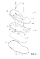
- FIGS. 1 and 2 show a perspective view of an infant seat according to an example of the present invention in assembled condition and as an exploded view of the main elements of said infant seat.
- the infant seat is referred to as 10 in its whole.
- FIG 2 it comprises a lower shell 11, an upper shell 12, a carrycot 20 being stored and encased within the infant seat 10 in a folded condition, a cushion 28 and a handle bar 29 which can be mounted to the infant seat 10 or alternatively to the carrycot 20 in a detachable manner, in order to seize this handle bar and carry the infant seat or the carrycot in a comfortable manner.
- the lower shell 11 has a receiving space 111, it is open to the top and has a concave shape seen from above.
- the space (volume) required for the infant seat 10 essentially is defined by the size and shape of the lower shell 11.
- the overall height of the mounted infant seat 10 only is slightly higher than the lower shell 1 alone, as the further elements, namely the upper shell 12, which has an inclined seat shape on its upper side, and the carrycot 20 are received at least in their major part in the receiving space 11 of the lower shell in the mounted condition.
- This kind of nested configuration of said elements 11, 12, 20 allows the storage of the carrycot within the infant seat of figure 1 . This results in the advantage that the mounted infant seat does not claim essentially more space than a conventional infant seat (without carrycot).
- the handle bar 29 When starting from the mounted condition shown in figure 1 first the handle bar 29 is detached.
- This may be for example a snap or click connection comprising snap buttons 293 at the ends of two legs 291 of the handle bar.
- These two legs 291 each have a push end 292, which can be inserted into a receipt 215 of a socket in the area of the joints 21 on a frame of the infant seat 10.
- These joints 21 are disposed on the frame 22, 23 which belongs to the carrycot 20 (see figure 2 ), which in the mounted condition is also the frame of the infant seat 10 in its whole.
- the joints 21 are accessible from the outside even in the mounted condition of the infant seat as can be seen from figure 1 , the joints each being disposed in the area of a recess in the lower shell 11 which can be seen from figure 2 .
- the snap buttons 293 lie in the snapped condition, the handle bar 29 being mounted, within the snap holes 216 of the sockets 215. If the user pushes onto the snap button from the outside, this moves inwardly, being mounted resiliently for instance with a spring, and the respective leg 291 of the handle bar can be pulled out of the receipt of the socket 215 and can be taken off.
- the upper shell 12 forms a solid rest for the infant and has a feet rest 121, a back rest 122, a seat area 15 with if necessary a cushion and belts 16 can be provided to fasten the infant.
- the lower shell 11 and the upper shell 12 are for example connected to each other by one or several zip fasteners 13, 14. These zip fasteners are disposed on the one hand in the area of the borders 124, 125 of the upper shell 12 and on the other hand in the area of the edges of the lower shell 11. After these zip fasteners have been opened the upper shell 12 can be removed from the lower shell 11. Thereby the carrycot 20 inside is accessible and can be taken out as well as the cushion 12. First the carrycot 20 is arranged in the folded condition wherein it needs little space as can be seen from figure 2 .
- the carrycot 20 in its outer dimensions preferably is somewhat smaller than the receiving space 111 of the lower shell 11 in its upper edge area, where the lower shell has its largest dimensions, such that the carrycot 20 with its outer frame 22, 23 fits into the lower shell 11. In its height the folded carrycot 20 does not claim much more space than itts outer frame as can be seen from figure 2 .
- Said carrycot comprises a bottom 25 which is sufficiently stable to support a baby, a foldable side area 24 comprising the side walls, a circumferential frame 22, 23 comprising two joints 21 being disposed essentially in the median area of the frame and lying opposite to each other.
- the outline shape of the frame 22, 23 may be essentially an elongated oval shape.
- the cushion 28 may be insertable into the foot rest and back rest of the carrycot 20 after taking it out of the infant seat.
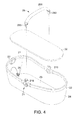
- the handle bar 29 is multifunctional as it can be mounted on the infant seat 10 in the complete seat configuration on one hand as can be seen from figure 1 , in order to carry the infant seat 10. After taking out the encased carrycot 20, the handle bar 29 can be remounted with the ends of its legs 291 to the joints 21 on the frame of the carrycot 20 as can be seen from figures 3 and 4 , such that the carrycot can be carried by means of the same handle bar 29.
- the two joints 21 which receive the respective bars of the frame 22, 23, which is composed of two essentially U-shaped brackets completing the elongated oval shape of the frame, each may have a T-shape with receiving sockets 215 directed to the top and two tubular sockets 213, 241 forming an angle of about 90 ° each to the receiving socket 215, said sockets 213, 241 thereby receiving the bars of the frame 22, 23. Furthermore located at the joints there is disposed a central connecting block 211 with an integrated connecting element 212, which serves to connect the infant seat 10 to the base frame of a baby carriage 30, which shall be explained in more detail referring to figure 5 hereafter.
- the carrycot 20 having been taken out of the infant seat 10 and thus being in the folded configuration as shown in figure 3 , can be unfolded by raising the circumferential frame 22, 23 in a direction perpendicular to the plane of the bottom 25, the fabric of the folded side walls of the side area 24 thereby being tensioned, such that the before low folded carrycot 20 is now transformed into a receptacle as shown in figure 4 , in which a baby can be transported.
- two plate-like support elements 27 are provided in the feet area and in the head area of the space of the carrycot 20, which can be pivoted outwards for about 90 ° from a lying state wherein they are arranged flat and parallel to the bottom 25 as shown in figure 3 into an upright position wherein they can be fixed by inserting them beneath the bars 22, 23 of the circumferential frame.
- One of the two support elements 27 can be seen in figure 4 in the upright position, wherein also hinge elements 26 are shown, on which the support element 27 is mounted pivoting to the bottom 25 of the carrycot.
- the shape of the support element 27 can be seen, which is made of a stiffer material which is, however, still somewhat flexible in order to make it possible to release it from the inserted position.
- the support element has a plate-like shape with a central recess 271 serving as engagement part such that there is the possibility to lay down the support element 27 starting from the vertical support position shown in figure 4 , in which it is seized beneath the rim of the frame 23, by gripping into the recess 271, bulging and slightly bending the support element 27 to release it and lay it down into the flat position before folding the carrycot 20 into the flat configuration, thereby folding the textile side area 24 of the carrycot.
- the tensioning of the side area 24 and thereby unfolding of the carrycot 20 into the upright position ready for use according to figure 4 can be carried out with a small number of hand movements only.
- the frame 22, 23 is arranged in an upper position, the side area 24 is unfolded and tensioned and it is stabilized by the support elements 27, such that the side area cannot be refolded by its own and the side area forms together with the bottom 25 a solid stable receptacle which delivers sufficient space to carry a baby or infant up to a certain age.
- the carrycot 20 may be unfolded (folding of the side area 24, see figure 3 ), such that it fits into the space between upper shell 12 and lower shell 11 and can be received by the receiving space 111 of the lower shell 11 (see figure 2 ) and in the mounted configuration according to figure 1 the device is both visually and functionally taken for an infant seat and can be used as such.
- the carrycot 20 in this mounted state is even not recognized, as it is encased in a kind of sandwich configuration between the inner space of upper shell 12 and lower shell 11.
- FIG. 5A shows in an enlarged scale the region of one of the joints 21 on the infant seat 10.
- connection block 211 comprising a flat protrusion as a connecting element 212, which can be pushed into the undercut receiving groove 311 and fits therein, such that the infant seat 10 may be hooked into the base frame 30 of the baby carriage.
- a snap connection with respective click elements may be provided (which is not shown), thereby avoiding an unintentional lift-off of the infant seat 10.
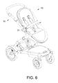
- Figure 5 intends to show the possibility to mount the infant seat 10 in a detachable manner onto the base frame 30 of a baby carriage. The resulting mounted configuration is shown in figure 6 .
- FIG 7 wherein it is shown that the infant seat 10 according to the present invention cannot only be mounted onto a base frame of a baby carriage but also, for instance can be mounted to a stand 40 alternatively, as for example it is used in bath rooms to lay down a baby safely in a high position.
- a stand 40 alternatively, as for example it is used in bath rooms to lay down a baby safely in a high position.
- Such a device as it is shown in figure 7 can also be used as a kind of high chair, in which the infant takes a lying or a sitting position.
- two mounting devices 41 can be arranged on the stand 40, which can be designed in a similar manner as the mounting devices 31 on the base frame 30 as shown in figure 5B .
- said mounting devices 41 can interact in a similar manner with the corresponding connecting elements 212 (see figure 5A ) of the infant seat 10, when mounting the infant seat to the stand 40.
- Figure 8 shows laminate sheet 50 of ethylene vinyl acetate and polyurethane in a flat state as a starting material, which is first put into a heating device 51 and which is heated therein for a time period of for example about 5 minutes up to a temperature of for example about 180 ° C to 190 ° C.
- the laminate sheet 50 which is softened, is then removed from the heating device 51, put into a mold of a thermoforming device and then molded and brought into a desired shape by the stroke of the mold, after said step having a desired pre-contour.
- Figure 9 shows the open thermoforming device with the upper mold 52 and the lower mold 53, which define the contour of the upper shell to be produced, in a state before the insertion of the laminate sheet 50.
- a vacuum force on one side of the sheet is generated and pressurized air on the other side of the sheet is used to push the sheet against the wall of the thermoforming mold.
- the two parts 52, 53 of the mold thereby will be cooled to cool down and solidify the laminate sheet.
- This process of cooling, shaping and solidifying may take some minutes, for example between about 3 and about 5 minutes. Thereafter the mold is opened and the shaped and solidified work piece (upper shell 54) can be taken out.
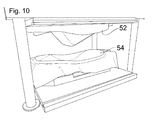
- Figure 10 shows the open mold of the thermoforming device after deformation with the inserting work piece 54 before it is cut.
- the work piece 54 can be cut in its peripheral region into the final shape.
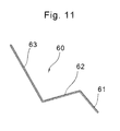
- FIG 11 showing in a schematic view of a section through the upper shell of an infant seat 60 according to a first embodiment of the present invention in order to illustrate the general shape of the infant seat.
- the contour comprises a leg rest 61, a seat part 62 and a back rest 63.
- All these parts of the upper shell can be produced by thermoforming from a single laminate sheet comprising at least two layers, one structural layer and one softer layer.
- the structural layer may for instance be the surface layer, but an additional surface layer also may be added, which may be from fabric, leather, synthetic leather of the like. Alternatively or additionally a further layer for instance from fabric may be added at the lower side (backside) of the laminate.
Landscapes
- Engineering & Computer Science (AREA)
- Chemical & Material Sciences (AREA)
- Combustion & Propulsion (AREA)
- Transportation (AREA)
- Mechanical Engineering (AREA)
- Carriages For Children, Sleds, And Other Hand-Operated Vehicles (AREA)
Applications Claiming Priority (1)
| Application Number | Priority Date | Filing Date | Title |
|---|---|---|---|
| TW098131349A TWI395563B (zh) | 2009-09-17 | 2009-09-17 | Baby seat device |
Publications (2)
| Publication Number | Publication Date |
|---|---|
| EP2298619A2 true EP2298619A2 (de) | 2011-03-23 |
| EP2298619A3 EP2298619A3 (de) | 2012-02-29 |
Family
ID=43333150
Family Applications (2)
| Application Number | Title | Priority Date | Filing Date |
|---|---|---|---|
| EP10000764A Not-in-force EP2298620B1 (de) | 2009-09-17 | 2010-01-26 | Kindersitz |
| EP10166919A Withdrawn EP2298619A3 (de) | 2009-09-17 | 2010-06-22 | Kindersitz und Verfahren zur Herstellung eines Kindersitzes |
Family Applications Before (1)
| Application Number | Title | Priority Date | Filing Date |
|---|---|---|---|
| EP10000764A Not-in-force EP2298620B1 (de) | 2009-09-17 | 2010-01-26 | Kindersitz |
Country Status (4)
| Country | Link |
|---|---|
| US (1) | US8276985B2 (de) |
| EP (2) | EP2298620B1 (de) |
| ES (1) | ES2426262T3 (de) |
| TW (1) | TWI395563B (de) |
Cited By (3)
| Publication number | Priority date | Publication date | Assignee | Title |
|---|---|---|---|---|
| WO2017103122A1 (fr) * | 2015-12-17 | 2017-06-22 | Dorel France | Nacelle pour enfant présentant une armature interne à structure asymétrique |
| CN108146488A (zh) * | 2016-12-13 | 2018-06-12 | 中山市乐瑞婴童用品有限公司 | 用于儿童推车且在躺卧状态和至少一个坐立状态之间进行转换的可转换支撑件及相应的推车 |
| NL2021321B1 (en) * | 2018-07-17 | 2020-01-24 | Royalty Bugaboo Gmbh | An infant supporting apparatus |
Families Citing this family (29)
| Publication number | Priority date | Publication date | Assignee | Title |
|---|---|---|---|---|
| JP2011079514A (ja) * | 2009-09-11 | 2011-04-21 | Phil & Teds Most Excellent Buggy Co Ltd | 小児運搬用押し車、モジュラー支持システム、および構成部品 |
| US8851569B2 (en) * | 2011-09-23 | 2014-10-07 | Chang-Hsien Ho | Full-cover and light-weight safety seat for child |
| CA2886259C (en) * | 2012-10-09 | 2020-03-24 | Dorel Juvenile Group, Inc. | Compactible stroller |
| CN103723181B (zh) * | 2012-10-15 | 2016-12-21 | 明门香港股份有限公司 | 顶篷装置、婴幼儿载具及其顶篷连接机构 |
| GB2511124B (en) * | 2013-02-26 | 2020-04-08 | Box Ltd | Ergonomic infant carrier |
| US9756961B2 (en) * | 2013-06-14 | 2017-09-12 | Wonderland Nurserygoods Company Limited | Adjusting mechanism and related child carrier |
| GB201420312D0 (en) * | 2014-11-14 | 2014-12-31 | Silver Cross Holdings Ltd | Carrier Mounting |
| TWI549847B (zh) * | 2015-02-16 | 2016-09-21 | Fran Wheel Entpr Co Ltd | A baby carriage with an auxiliary wheel device |
| JP6758905B2 (ja) * | 2016-05-09 | 2020-09-23 | コンビ株式会社 | 乳母車 |
| US10618435B2 (en) | 2016-08-25 | 2020-04-14 | Dorel Juvenille Group, Inc. | Infant carrier |
| WO2018039435A1 (en) * | 2016-08-25 | 2018-03-01 | Dorel Juvenile Group, Inc. | Infant carrier |
| USD859862S1 (en) | 2017-09-13 | 2019-09-17 | Kids Ii, Inc. | Rocker |
| US11001288B2 (en) | 2017-09-29 | 2021-05-11 | Stanley Carl Valiulis | Car seat holder |
| US11641952B2 (en) | 2019-06-21 | 2023-05-09 | Kids2, Inc. | Modular cradle |
| CN113116079A (zh) * | 2020-01-10 | 2021-07-16 | 明门瑞士股份有限公司 | 支撑板及睡箱 |
| EP4296118A3 (de) * | 2020-01-10 | 2024-05-01 | Thule Sweden AB | Fahrradkindersitz und verfahren zur montage eines fahrradkindersitzes |
| TWI871928B (zh) * | 2020-05-14 | 2025-02-01 | 瑞士商寶鉅瑞士股份有限公司 | 睡箱以及相關的兒童載具 |
| CN117818736A (zh) * | 2020-05-14 | 2024-04-05 | 宝钜瑞士股份有限公司 | 睡箱、睡箱结构及婴儿载具 |
| US11357338B2 (en) * | 2020-05-31 | 2022-06-14 | Paul Anthony Fulcher, JR. | Wearable baby carriers with multiple operation modes, and baby support systems comprising such wearable baby carriers |
| JP7617246B2 (ja) * | 2020-08-11 | 2025-01-17 | ワンダーランド スイツァーランド アーゲー | 手すりアセンブリ、その製造方法、支持フレーム構造体及び子供用キャリア |
| USD978545S1 (en) | 2020-09-17 | 2023-02-21 | Kids2, Inc. | Modular highchair |
| USD979259S1 (en) | 2020-09-17 | 2023-02-28 | Kids2, Inc. | Modular swing |
| USD958897S1 (en) | 2020-09-17 | 2022-07-26 | Kids2, Inc. | Modular toy bar |
| USD977865S1 (en) | 2020-09-17 | 2023-02-14 | Kids2, Inc. | Modular cradle |
| US11654948B2 (en) | 2021-08-09 | 2023-05-23 | Stanley Carl Valiulis | Car seat holder |
| CN115844166B (zh) * | 2021-09-24 | 2025-04-01 | 明门瑞士股份有限公司 | 婴儿睡篮 |
| USD1042243S1 (en) * | 2022-07-19 | 2024-09-17 | Mima International Holdings Limited | Baby carriage |
| PL441862A1 (pl) * | 2022-07-27 | 2024-01-29 | Czupryna Sławomir Center-Tuning | Gondola wózka, zwłaszcza dziecięcego |
| USD1061351S1 (en) * | 2022-08-11 | 2025-02-11 | Mima International Holdings Limited | Baby carriage |
Family Cites Families (16)
| Publication number | Priority date | Publication date | Assignee | Title |
|---|---|---|---|---|
| DE1654291A1 (de) * | 1967-12-13 | 1971-03-25 | Kusch & Co Gmbh | Moebelstueck aus Kunststoff,insbesondere fuer Kinder |
| US3596986A (en) * | 1970-03-30 | 1971-08-03 | Gen Motors Corp | Baby seat |
| US4664396A (en) * | 1985-07-30 | 1987-05-12 | Eugene Doll & Novelty Co., Inc. | Multi-function baby doll accessory |
| US4743063A (en) * | 1987-06-18 | 1988-05-10 | Foster Jr James W | Convertible multi-function child restraint system |
| US5127120A (en) * | 1991-08-01 | 1992-07-07 | Mason Cynthia A | Infant support pad |
| DE19527351C2 (de) * | 1995-07-26 | 1999-01-07 | Bayerische Motoren Werke Ag | Kindersitz |
| US6010184A (en) * | 1998-02-17 | 2000-01-04 | John A. Helmsderfer | Child support device with removable seat element |
| US6679550B2 (en) * | 1998-10-13 | 2004-01-20 | Xsci, Inc. | Child safety seat |
| DE29903241U1 (de) * | 1999-02-23 | 1999-05-12 | Trends For Kids Vertriebs GmbH, 84032 Landshut | Dreirädiger Schiebewagen für Kinder und/oder Puppen |
| JP2002011781A (ja) * | 2000-06-29 | 2002-01-15 | Tachi S Co Ltd | シートの加熱加圧成形型 |
| EP1363772B1 (de) * | 2001-02-06 | 2004-10-06 | Fagerdala Deutschland GmbH | Verbundmaterial aus einer polypropylen-deckschicht sowie einer polypropylen-schaumfolie |
| GB2419520B (en) * | 2004-09-28 | 2008-04-09 | Armon Ltd | Convertible seat for a baby buggy |
| ES2666274T3 (es) * | 2005-03-23 | 2018-05-03 | Milsco Manufacturing, A Unit Of Jason Incorporated | Montaje de asiento con ajuste integrado |
| JP2007099214A (ja) * | 2005-10-07 | 2007-04-19 | Takata Corp | チャイルドシート |
| TWM311627U (en) * | 2006-10-17 | 2007-05-11 | Link Treasure Ltd | Safety carrier for infant with a one-handed release mechanism |
| US7909400B1 (en) * | 2007-04-02 | 2011-03-22 | Todd Delaney | Modular child safety seat for vehicles |
-
2009
- 2009-09-17 TW TW098131349A patent/TWI395563B/zh not_active IP Right Cessation
-
2010
- 2010-01-26 EP EP10000764A patent/EP2298620B1/de not_active Not-in-force
- 2010-01-26 ES ES10000764T patent/ES2426262T3/es active Active
- 2010-06-22 EP EP10166919A patent/EP2298619A3/de not_active Withdrawn
- 2010-07-12 US US12/834,332 patent/US8276985B2/en active Active
Cited By (5)
| Publication number | Priority date | Publication date | Assignee | Title |
|---|---|---|---|---|
| WO2017103122A1 (fr) * | 2015-12-17 | 2017-06-22 | Dorel France | Nacelle pour enfant présentant une armature interne à structure asymétrique |
| FR3045522A1 (fr) * | 2015-12-17 | 2017-06-23 | Dorel France Sa | Nacelle pour enfant presentant une armature interne a structure asymetrique |
| CN108146488A (zh) * | 2016-12-13 | 2018-06-12 | 中山市乐瑞婴童用品有限公司 | 用于儿童推车且在躺卧状态和至少一个坐立状态之间进行转换的可转换支撑件及相应的推车 |
| CN108146488B (zh) * | 2016-12-13 | 2021-04-16 | 中山市乐瑞婴童用品有限公司 | 用于儿童推车且在躺卧状态和至少一个坐立状态之间进行转换的可转换支撑件及相应的推车 |
| NL2021321B1 (en) * | 2018-07-17 | 2020-01-24 | Royalty Bugaboo Gmbh | An infant supporting apparatus |
Also Published As
| Publication number | Publication date |
|---|---|
| US20110062752A1 (en) | 2011-03-17 |
| EP2298620B1 (de) | 2013-03-27 |
| ES2426262T3 (es) | 2013-10-22 |
| TWI395563B (zh) | 2013-05-11 |
| US8276985B2 (en) | 2012-10-02 |
| EP2298620A2 (de) | 2011-03-23 |
| TW201110916A (en) | 2011-04-01 |
| EP2298619A3 (de) | 2012-02-29 |
| EP2298620A3 (de) | 2012-02-22 |
Similar Documents
| Publication | Publication Date | Title |
|---|---|---|
| EP2298619A2 (de) | Kindersitz und Verfahren zur Herstellung eines Kindersitzes | |
| US5129705A (en) | Head support | |
| US9585494B2 (en) | Infant lounger | |
| US20050241064A1 (en) | Convertible infant care apparatus | |
| US8950808B2 (en) | Stowable baby seat and methods | |
| JP5383103B2 (ja) | 2つの機能を兼ねる子供用椅子 | |
| KR101851415B1 (ko) | 아기 받침대 및 장착 장치 | |
| US8104840B2 (en) | Attachable and detachable type seat pad and method of fabricating the same, and seat using attachable and detachable type seat pad | |
| EP3300636A1 (de) | Kinderstützsystem mit mehreren positionen | |
| US20080217973A1 (en) | Portable booster seat | |
| WO1997043931A1 (en) | Collapsible and convertible baby bed and carrier | |
| US20050146181A1 (en) | Triangular child's booster seat | |
| AU2015215622A1 (en) | Improvements in or related to child carrying units | |
| HK1217620A1 (zh) | 婴儿支承座椅 | |
| CN1212796C (zh) | 襁褓兜袋以及用于襁褓兜袋的婴儿用头部保持件 | |
| CN102316842A (zh) | 按摩椅 | |
| JP2001000281A (ja) | 組み立て式マットレス | |
| KR102228754B1 (ko) | 기능성 하이 체어 | |
| CN112056864A (zh) | 用于可转换的儿童垫高椅的系统、方法和装置 | |
| WO2018150368A1 (en) | Multifunctional baby bassinet | |
| KR20110004620A (ko) | 차량용 유아놀이방 매트 | |
| JP2000023801A (ja) | 乳幼児保持具 | |
| CN223489433U (zh) | 基板和床垫组件 | |
| JP3130455B2 (ja) | 乳幼児保持具 | |
| KR200325460Y1 (ko) | 다기능 유아용 포대기 |
Legal Events
| Date | Code | Title | Description |
|---|---|---|---|
| PUAI | Public reference made under article 153(3) epc to a published international application that has entered the european phase |
Free format text: ORIGINAL CODE: 0009012 |
|
| AK | Designated contracting states |
Kind code of ref document: A2 Designated state(s): AL AT BE BG CH CY CZ DE DK EE ES FI FR GB GR HR HU IE IS IT LI LT LU LV MC MK MT NL NO PL PT RO SE SI SK SM TR |
|
| AX | Request for extension of the european patent |
Extension state: BA ME RS |
|
| PUAL | Search report despatched |
Free format text: ORIGINAL CODE: 0009013 |
|
| AK | Designated contracting states |
Kind code of ref document: A3 Designated state(s): AL AT BE BG CH CY CZ DE DK EE ES FI FR GB GR HR HU IE IS IT LI LT LU LV MC MK MT NL NO PL PT RO SE SI SK SM TR |
|
| AX | Request for extension of the european patent |
Extension state: BA ME RS |
|
| RIC1 | Information provided on ipc code assigned before grant |
Ipc: A47D 13/02 20060101ALI20120120BHEP Ipc: B62B 9/10 20060101ALI20120120BHEP Ipc: B29C 51/08 20060101ALI20120120BHEP Ipc: A47D 1/10 20060101ALI20120120BHEP Ipc: B62B 7/14 20060101AFI20120120BHEP |
|
| STAA | Information on the status of an ep patent application or granted ep patent |
Free format text: STATUS: THE APPLICATION IS DEEMED TO BE WITHDRAWN |
|
| 18D | Application deemed to be withdrawn |
Effective date: 20120830 |