EP2299008A1 - Structure du bonnet pour le moteur d'une machine d'operation - Google Patents
Structure du bonnet pour le moteur d'une machine d'operation Download PDFInfo
- Publication number
- EP2299008A1 EP2299008A1 EP10171851A EP10171851A EP2299008A1 EP 2299008 A1 EP2299008 A1 EP 2299008A1 EP 10171851 A EP10171851 A EP 10171851A EP 10171851 A EP10171851 A EP 10171851A EP 2299008 A1 EP2299008 A1 EP 2299008A1
- Authority
- EP
- European Patent Office
- Prior art keywords
- shield
- structure according
- bonnet
- vertical
- engine
- Prior art date
- Legal status (The legal status is an assumption and is not a legal conclusion. Google has not performed a legal analysis and makes no representation as to the accuracy of the status listed.)
- Granted
Links
- 230000007246 mechanism Effects 0.000 claims abstract description 13
- 238000005273 aeration Methods 0.000 claims abstract description 10
- 210000003660 reticulum Anatomy 0.000 claims description 50
- 239000000463 material Substances 0.000 claims description 5
- 238000012423 maintenance Methods 0.000 description 9
- 230000000903 blocking effect Effects 0.000 description 5
- 238000002485 combustion reaction Methods 0.000 description 5
- 238000001816 cooling Methods 0.000 description 5
- 230000004224 protection Effects 0.000 description 4
- 238000006722 reduction reaction Methods 0.000 description 4
- 230000000694 effects Effects 0.000 description 3
- 238000005553 drilling Methods 0.000 description 2
- 230000008439 repair process Effects 0.000 description 2
- 238000004378 air conditioning Methods 0.000 description 1
- 230000000712 assembly Effects 0.000 description 1
- 238000000429 assembly Methods 0.000 description 1
- 238000013475 authorization Methods 0.000 description 1
- 238000009412 basement excavation Methods 0.000 description 1
- 238000010531 catalytic reduction reaction Methods 0.000 description 1
- 238000004891 communication Methods 0.000 description 1
- 238000007596 consolidation process Methods 0.000 description 1
- 238000010276 construction Methods 0.000 description 1
- 230000001419 dependent effect Effects 0.000 description 1
- 238000009792 diffusion process Methods 0.000 description 1
- 238000006073 displacement reaction Methods 0.000 description 1
- 238000010438 heat treatment Methods 0.000 description 1
- 239000010720 hydraulic oil Substances 0.000 description 1
- 238000003780 insertion Methods 0.000 description 1
- 230000037431 insertion Effects 0.000 description 1
- 238000009434 installation Methods 0.000 description 1
- 239000007788 liquid Substances 0.000 description 1
- 239000002184 metal Substances 0.000 description 1
- 239000002699 waste material Substances 0.000 description 1
- XLYOFNOQVPJJNP-UHFFFAOYSA-N water Substances O XLYOFNOQVPJJNP-UHFFFAOYSA-N 0.000 description 1
Images


Classifications
-
- E—FIXED CONSTRUCTIONS
- E02—HYDRAULIC ENGINEERING; FOUNDATIONS; SOIL SHIFTING
- E02F—DREDGING; SOIL-SHIFTING
- E02F9/00—Component parts of dredgers or soil-shifting machines, not restricted to one of the kinds covered by groups E02F3/00 - E02F7/00
- E02F9/08—Superstructures; Supports for superstructures
- E02F9/0858—Arrangement of component parts installed on superstructures not otherwise provided for, e.g. electric components, fenders, air-conditioning units
- E02F9/0891—Lids or bonnets or doors or details thereof
-
- B—PERFORMING OPERATIONS; TRANSPORTING
- B62—LAND VEHICLES FOR TRAVELLING OTHERWISE THAN ON RAILS
- B62D—MOTOR VEHICLES; TRAILERS
- B62D25/00—Superstructure or monocoque structure sub-units; Parts or details thereof not otherwise provided for
- B62D25/08—Front or rear portions
- B62D25/10—Bonnets or lids, e.g. for trucks, tractors, busses, work vehicles
-
- E—FIXED CONSTRUCTIONS
- E02—HYDRAULIC ENGINEERING; FOUNDATIONS; SOIL SHIFTING
- E02F—DREDGING; SOIL-SHIFTING
- E02F9/00—Component parts of dredgers or soil-shifting machines, not restricted to one of the kinds covered by groups E02F3/00 - E02F7/00
Definitions
- the present invention relates to a bonnet structure for an engine body of a machine.
- the present invention relates to a bonnet structure that can be associated to machines of the type used in the sector of foundations (for example earth-moving machinery, boring machines and cranes, either tracked or on wheels), adapted to cover an opening for access to the compartment of the engine body.
- the part of operating machine that has as casing the bonnet in question is generally defined as: "engine compartment” or "base machine” or "turret”.
- a solution currently adopted envisages adding in the area of the bonnets of the engine compartment traditional external appendages closed on three sides and at the bottom and open only upwards, in such a way as to create a top opening and enable cooling and a good passage of air, and at the same time, since they reflect the noise upwards, they have the effect of reducing the level of noise perceived at operator level.
- the top opening is generally protected by grills to prevent undesirable material from possibly being drawn in (e.g., leaves, stones, etc.).
- the present invention overcomes the aforesaid drawbacks by providing a bonnet structure without aeration openings that, with a substantially vertical movement, can be raised to enable adequate access to the engine compartment for the necessary maintenance operations, with minimum occupation of space outwards during the displacements between the closed position and the raised position and by providing a fall-prevention parapet for the top walkways of the base machine; with a rocking movement (either manual or automatic) it can be opened to guarantee adequate circulation of the air necessary for the radiant masses, in any case reducing the noise perceived at operator level, and can be reclosed, eliminating the need for providing additional components to be removed during the steps of transportation.
- bonnet structure 2 can be applied to an operating machine, already described previously (including in this definition all machines that carry out works for laying foundations, such as: drilling, consolidation, pile driving, excavation, digging of trenches, and hoisting machines, such as for example cranes) in the lateral position (where by "lateral” is meant the left side or right side of the operating machine, not including the front side, which is generally left free for the cab and the rear side, where a counterweight is generally present), in the proximity of a possible parapet P that protects a communication trench C or walkway, used for operations of maintenance, repair, and adjustments, or else for the operations of opening and closing of the bonnet itself or as access to driving cab 40.
- lateral is meant the left side or right side of the operating machine, not including the front side, which is generally left free for the cab and the rear side, where a counterweight is generally present
- a possible parapet P that protects a communication trench C or walkway, used for operations of maintenance, repair, and adjustments, or else for the operations of opening and
- the structure comprises at least one substantially vertical shield 21, preferably without aeration openings, and at least one substantially horizontal cover 22, adapted in a closed position to join along an edge of their own and to shield an opening within which the engine and/or the radiant masses to be subjected to aeration are present.
- Said shield 21 can be brought into a first, open, position, or aeration position, via rotation about a horizontal bottom axis O, so as to set itself inclined with respect to the vertical and to generate an open space between its top edge and top cover 22, said open space having the function of air passage and in particular of air intake in the case where the flow is an intake flow, or emission outlet in the opposite case, i.e., in the case of a forcing flow of air.
- This position is considered as working position; consequently, it has the characteristic of having to remain in this geometrical configuration without creating problems for operation of the internal components of the machine and simultaneously allow full visibility for the operator.
- Said top open space is advantageously occupied by at least one grill 23, which can be purposely pulled shut manually when it is necessary to prevent intrusion of undesirable elements within the compartment that might damage the radiant masses or the components inside the base machine.
- the grill can also be actuated automatically, for example by constraining it to shield 21 and getting it to move simultaneously with opening of the latter. For example by drawing it along an appropriate counterframe (not represented) equipped with guides and fixed to top cover 22 or to frame 24. At least one vertical element 25 is set on each of the side walls of the compartment, created when the shield is brought into an open position, so as to keep the substantially vertical walls shielded.
- the vertical shield is constrained to a frame 24, preferably sized for supporting the structure of the bonnet, by means of said opposed vertical elements 25, made advantageously of rigid soundproofing material.
- elements 25 are connected together to frame 24 and to shield 21 with hinges set on the edges so as to enable their arrangement in a direction parallel to the shield itself when this is in a position with the air intake or the emission mouth closed, thus minimizing the encumbrance thereof.
- elements 25 When the shield is closed, elements 25 will be set on top of one another in bellows fashion.
- the embodiment of elements 25 could be obtained in multiple ways: with proper bellows, with flexible structures made of a material and with a thickness suitable for shielding the noise, telescopic, or again slidable, or else pivoting on a hinge that is fixed with respect to axis of rotation O of vertical shield 21.
- the characteristic that all these embodiments share is that of passing from a position where the shield is entirely contained inside the engine compartment, when it is in a closed position, to a position of lateral shielding, when the shield is open so as to provide a top air passage.
- the top opening hence enables the air to pass in the two directions, i.e., both into and out of the machine, enabling inlet of fresh air for the radiant masses or outlet of hot air (deriving from the forced cooling of the radiant masses or from the internal-combustion engine)that are generally positioned opposed to one another in the internal architecture of the base machine so as not to interfere with one another.
- the outlet of hot air enables the internal temperature to be stabilized at lower values.
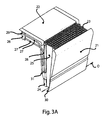
- the bonnet structure further comprises a main support 26 for engagement to the load-bearing structure of the machine, and a mechanism for moving shield 21 and possibly top covering panel 22 and grill 23. Said mechanism is able to move the shield itself substantially in a vertical direction parallel to itself so that the bonnet structure in a raised position presents shield 21 above said opening, substantially aligned and parallel to when it is in a closed position.
- the bonnet structure comprises for each of its sides two rigid arms 27 that constitute the elements of connection between shield 21 and frame 26 typical of articulated-parallelogram or pantograph mechanisms, pivoted at one of their ends 31 to the main support and at the opposite end to frame 24 of the bonnet structure through hinges 29 so as to be able to rotate and keep shield 21 with a substantially vertical orientation when the latter is being raised.
- the points of junction of the arms on the main support enable the entire bonnet to be raised at the same time minimizing the encumbrance outwards.
- the opening systems most widely used in the sector of operating machines are provided by hinges with vertical axis that secure the vertical shield to the frame, making it pivoting with respect thereto.
- the width of the panels for access to the base machine is sized in relation to the required degree of internal accessibility and to the type of components. In many cases, these panels can reach and exceed 2 m in length. It is evident how this represents a severe limit as walkways C equipped with parapet P must consequently be of adequate width such as to enable complete opening of the panel (and hence they must exceed two metres in width, which entails encumbrance and weights that are difficult to handle during transportation). Consequently, providing an opening mechanism that occupies a minimum encumbrance (less than 40 cm) on the parapet, it enables instead provision of narrower walkways and full compatibility with the presence of parapet P. Furthermore, it also enables working with the operating machine on the worksite given that its encumbrance in width are reduced to the bare minimum.
- said arms 27 are preferably shaped substantially at right angles, and the structure is raised preferably with the aid of at least one spring device 28 (typically gas-operated springs such as the ones used in the automotive sector) to facilitate movement thereof as this reduces the effort required by the operator for opening the shield and advantageously blocks the shield itself in the raised position.
- spring device 28 typically gas-operated springs such as the ones used in the automotive sector
- an arrest device not represented for example a bolt, a blocking rod, etc.
- Figure 2d shows a variant of the solution described previously, in which top cover 22 remains fixed to the frame, whilst just the vertical shield is brought into the raised position.
- This solution enables the lifting of lighter structures, but on the other hand does not leave a good degree of accessibility for maintenance operations and freedom of movement on the top walkways.
- the movement mechanism comprises a pair of lateral telescopic guides 31 supported by spring devices 28 (typically gas-operated springs), which are able to assist raising of shield 21 in a vertical direction and possibly to keep it fixed in the raised position.
- spring devices 28 typically gas-operated springs
- this latter type of solution enables yet a further reduction in the external encumbrance in the direction of the walkway, during the raising steps, in which the panel moves parallel to itself and thus enables a reduction to a minimum of the widths of the walkways themselves.
- the absence of the arms of the mechanism leaves the passage free for a top walkway on the bonnets, which allows freedom of movement of working staff.
- the bonnet in the raised position and blocked by an appropriate arrest device (not represented), can function as fall-prevention parapet if appropriately sized for the purpose so as to comply with standard requirements.
- the device for blocking shield 21 in the raised position could be rendered accessible only from the bottom position in such a way that the persons that transit along the top walkway cannot release it in any way, with the risk of causing shield 21 to drop down, thus in effect removing the fall-prevention protection. In this case, then, to guarantee safe access to the top parts of the bonnet it will be sufficient to raise all the bonnets, blocking them in the top position.
- the telescopic guides are able to raise also the cover itself so as to enable opening of a passage in the bonnets, thus creating an access both from the front and from the top and hence making for greater accessibility in the case of maintenance.
- the vertical shield As described previously for the first embodiment and as shown in Figure 3b , it is possible also in this case to get the vertical shield to oscillate about a horizontal bottom axis O so as to set it inclined with respect to the vertical and generate an open space between its top edge and top cover 22. As described previously, there will be present lateral elements with a shielding function. In this way, it is possible not to provide openings on the vertical wall of shield 21, thus reducing the noise emitted at worker level.
- the foldable elements that constitute the side walls of the bonnet in the open position can be made directly of rigid soundproofing material.
- they can be metal shields, bellows, or any type of flexible element that shields noise.
- opening and closing of the embodiments of bonnet described can be carried out manually when the machine passes from an inactive condition to an operating condition, and vice versa. It is possible also to automate the movement and render it remote-controlled, directly from the driving seat (in this case, the system is completed with actuators controlled by appropriate, preferably electrically or hydraulically controlled selectors).
- the system is equipped with an automatic drive, this can be activated either by the operator or by a control of the temperature of the engine compartment, which, once a minimum threshold is reached, will activates opening of the bonnets, enabling the air to pass through the top openings.
- opening is controlled by actuators it could even be partialized and not merely be of an on-off type (i.e., all open or all closed).
- the bonnet Once the bonnet is reclosed, it can be moved from an all-closed position to a raised position (to enable access for maintenance operations), without excessively invading the space at the sides. This enables reduction to a minimum of the widths of the walkways, enabling simultaneous presence of the parapets, to the advantage of safety.
- the bonnets in the raised position can assume the role of fall-prevention protections (parapets) for walkways on the uppermost bonnets, which are required for carrying out maintenance operations.
- the movement of the shield into the open position or position of aeration could occur not only by rocking about a bottom axis, but also by translating possibly in a non-symmetrical way so that the top portion is much more distant from the frame than the bottom one.
- the aeration opening in some cases could even be set facing downwards (if required to increase the air passages or to simplify the structure of the bonnet itself and of its mechanism).
- the shield In the aeration position, the shield can be provided at the bottom with a device 30 for collecting and conveying water, thus preventing the latter from possibly entering the engine compartment.
Landscapes
- Engineering & Computer Science (AREA)
- Mining & Mineral Resources (AREA)
- Civil Engineering (AREA)
- General Engineering & Computer Science (AREA)
- Structural Engineering (AREA)
- Chemical & Material Sciences (AREA)
- Combustion & Propulsion (AREA)
- Transportation (AREA)
- Mechanical Engineering (AREA)
- Superstructure Of Vehicle (AREA)
- Component Parts Of Construction Machinery (AREA)
- Lock And Its Accessories (AREA)
Applications Claiming Priority (1)
| Application Number | Priority Date | Filing Date | Title |
|---|---|---|---|
| ITTO2009A000707A IT1398783B1 (it) | 2009-09-17 | 2009-09-17 | Struttura di cofano per un corpo motore di una macchina operatrice |
Publications (2)
| Publication Number | Publication Date |
|---|---|
| EP2299008A1 true EP2299008A1 (fr) | 2011-03-23 |
| EP2299008B1 EP2299008B1 (fr) | 2013-05-15 |
Family
ID=41667271
Family Applications (1)
| Application Number | Title | Priority Date | Filing Date |
|---|---|---|---|
| EP20100171851 Not-in-force EP2299008B1 (fr) | 2009-09-17 | 2010-08-04 | Structure du bonnet pour le moteur d'une machine d'operation |
Country Status (2)
| Country | Link |
|---|---|
| EP (1) | EP2299008B1 (fr) |
| IT (1) | IT1398783B1 (fr) |
Cited By (3)
| Publication number | Priority date | Publication date | Assignee | Title |
|---|---|---|---|---|
| EP2829663A1 (fr) * | 2013-07-22 | 2015-01-28 | BAUER Maschinen GmbH | Tourelle pour un engin de chantier |
| US9404238B1 (en) | 2015-01-10 | 2016-08-02 | Bauer Maschinen Gmbh | Construction machine |
| CN109306716A (zh) * | 2018-11-14 | 2019-02-05 | 徐州徐工矿山机械有限公司 | 一种多功能护罩结构及挖掘机 |
Citations (3)
| Publication number | Priority date | Publication date | Assignee | Title |
|---|---|---|---|---|
| WO2001076912A1 (fr) * | 2000-04-11 | 2001-10-18 | Volvo Articulated Haulers Ab | Carter-moteur |
| WO2007032242A1 (fr) * | 2005-09-15 | 2007-03-22 | Komatsu Ltd. | Dispositif de refroidissement pour engin de chantier |
| US20090140548A1 (en) * | 2007-12-03 | 2009-06-04 | Caterpillar Paving Products Inc. | Sliding panel arrangement for a vehicle |
-
2009
- 2009-09-17 IT ITTO2009A000707A patent/IT1398783B1/it active
-
2010
- 2010-08-04 EP EP20100171851 patent/EP2299008B1/fr not_active Not-in-force
Patent Citations (3)
| Publication number | Priority date | Publication date | Assignee | Title |
|---|---|---|---|---|
| WO2001076912A1 (fr) * | 2000-04-11 | 2001-10-18 | Volvo Articulated Haulers Ab | Carter-moteur |
| WO2007032242A1 (fr) * | 2005-09-15 | 2007-03-22 | Komatsu Ltd. | Dispositif de refroidissement pour engin de chantier |
| US20090140548A1 (en) * | 2007-12-03 | 2009-06-04 | Caterpillar Paving Products Inc. | Sliding panel arrangement for a vehicle |
Cited By (4)
| Publication number | Priority date | Publication date | Assignee | Title |
|---|---|---|---|---|
| EP2829663A1 (fr) * | 2013-07-22 | 2015-01-28 | BAUER Maschinen GmbH | Tourelle pour un engin de chantier |
| EP3135824A1 (fr) * | 2013-07-22 | 2017-03-01 | BAUER Maschinen GmbH | Tourelle pour un engin |
| US9404238B1 (en) | 2015-01-10 | 2016-08-02 | Bauer Maschinen Gmbh | Construction machine |
| CN109306716A (zh) * | 2018-11-14 | 2019-02-05 | 徐州徐工矿山机械有限公司 | 一种多功能护罩结构及挖掘机 |
Also Published As
| Publication number | Publication date |
|---|---|
| IT1398783B1 (it) | 2013-03-18 |
| ITTO20090707A1 (it) | 2011-03-18 |
| EP2299008B1 (fr) | 2013-05-15 |
Similar Documents
| Publication | Publication Date | Title |
|---|---|---|
| EP2248695B1 (fr) | Engin de chantier | |
| KR101896579B1 (ko) | 건설 기계 | |
| WO2011033732A1 (fr) | Engin de chantier | |
| JP6392707B2 (ja) | 作業機械 | |
| EP2299008B1 (fr) | Structure du bonnet pour le moteur d'une machine d'operation | |
| JP2016069977A (ja) | 建設機械 | |
| JP6600583B2 (ja) | 建設機械および建設機械のエンジンカバー取付方法 | |
| US20130223967A1 (en) | Working Machine | |
| US9670647B2 (en) | Work vehicle | |
| JP6352758B2 (ja) | 建設機械 | |
| JP6225796B2 (ja) | 建設機械 | |
| JP5934637B2 (ja) | 建設機械 | |
| CN104074221A (zh) | 施工机械 | |
| CN204370501U (zh) | 工程机械上部平台外观件的防护装置和工程机械 | |
| JP6286344B2 (ja) | 建設機械 | |
| JP4134013B2 (ja) | 旋回作業機の後上部支持フレーム構造 | |
| JP5891111B2 (ja) | 作業車両 | |
| JP4226506B2 (ja) | 旋回作業機の作業操作部構造 | |
| JP2016216998A (ja) | 建設機械 | |
| KR101559173B1 (ko) | 엔진룸 공기 순환구조 | |
| JP2004257000A (ja) | 建設機械のバッテリ取付装置及び建設機械 | |
| JP2001159152A (ja) | 建設機械の冷却装置 | |
| JP7643375B2 (ja) | 建設機械 | |
| JP2005280485A (ja) | 旋回作業機のカバー装置 | |
| JP2021021188A (ja) | 建設機械 |
Legal Events
| Date | Code | Title | Description |
|---|---|---|---|
| PUAI | Public reference made under article 153(3) epc to a published international application that has entered the european phase |
Free format text: ORIGINAL CODE: 0009012 |
|
| AK | Designated contracting states |
Kind code of ref document: A1 Designated state(s): AL AT BE BG CH CY CZ DE DK EE ES FI FR GB GR HR HU IE IS IT LI LT LU LV MC MK MT NL NO PL PT RO SE SI SK SM TR |
|
| AX | Request for extension of the european patent |
Extension state: BA ME RS |
|
| 17P | Request for examination filed |
Effective date: 20110916 |
|
| 17Q | First examination report despatched |
Effective date: 20120322 |
|
| REG | Reference to a national code |
Ref country code: DE Ref legal event code: R079 Ref document number: 602010007048 Country of ref document: DE Free format text: PREVIOUS MAIN CLASS: E02F0009080000 Ipc: B62D0025100000 |
|
| GRAP | Despatch of communication of intention to grant a patent |
Free format text: ORIGINAL CODE: EPIDOSNIGR1 |
|
| RIC1 | Information provided on ipc code assigned before grant |
Ipc: E02F 9/08 20060101ALI20121030BHEP Ipc: B62D 25/10 20060101AFI20121030BHEP Ipc: E02F 9/00 20060101ALI20121030BHEP |
|
| GRAS | Grant fee paid |
Free format text: ORIGINAL CODE: EPIDOSNIGR3 |
|
| GRAA | (expected) grant |
Free format text: ORIGINAL CODE: 0009210 |
|
| AK | Designated contracting states |
Kind code of ref document: B1 Designated state(s): AL AT BE BG CH CY CZ DE DK EE ES FI FR GB GR HR HU IE IS IT LI LT LU LV MC MK MT NL NO PL PT RO SE SI SK SM TR |
|
| REG | Reference to a national code |
Ref country code: GB Ref legal event code: FG4D Ref country code: CH Ref legal event code: EP |
|
| REG | Reference to a national code |
Ref country code: AT Ref legal event code: REF Ref document number: 611999 Country of ref document: AT Kind code of ref document: T Effective date: 20130615 |
|
| REG | Reference to a national code |
Ref country code: IE Ref legal event code: FG4D |
|
| REG | Reference to a national code |
Ref country code: DE Ref legal event code: R096 Ref document number: 602010007048 Country of ref document: DE Effective date: 20130711 |
|
| REG | Reference to a national code |
Ref country code: AT Ref legal event code: MK05 Ref document number: 611999 Country of ref document: AT Kind code of ref document: T Effective date: 20130515 |
|
| REG | Reference to a national code |
Ref country code: LT Ref legal event code: MG4D |
|
| REG | Reference to a national code |
Ref country code: NL Ref legal event code: VDEP Effective date: 20130515 |
|
| PG25 | Lapsed in a contracting state [announced via postgrant information from national office to epo] |
Ref country code: IS Free format text: LAPSE BECAUSE OF FAILURE TO SUBMIT A TRANSLATION OF THE DESCRIPTION OR TO PAY THE FEE WITHIN THE PRESCRIBED TIME-LIMIT Effective date: 20130915 Ref country code: NO Free format text: LAPSE BECAUSE OF FAILURE TO SUBMIT A TRANSLATION OF THE DESCRIPTION OR TO PAY THE FEE WITHIN THE PRESCRIBED TIME-LIMIT Effective date: 20130815 Ref country code: PT Free format text: LAPSE BECAUSE OF FAILURE TO SUBMIT A TRANSLATION OF THE DESCRIPTION OR TO PAY THE FEE WITHIN THE PRESCRIBED TIME-LIMIT Effective date: 20130916 Ref country code: AT Free format text: LAPSE BECAUSE OF FAILURE TO SUBMIT A TRANSLATION OF THE DESCRIPTION OR TO PAY THE FEE WITHIN THE PRESCRIBED TIME-LIMIT Effective date: 20130515 Ref country code: SI Free format text: LAPSE BECAUSE OF FAILURE TO SUBMIT A TRANSLATION OF THE DESCRIPTION OR TO PAY THE FEE WITHIN THE PRESCRIBED TIME-LIMIT Effective date: 20130515 Ref country code: LT Free format text: LAPSE BECAUSE OF FAILURE TO SUBMIT A TRANSLATION OF THE DESCRIPTION OR TO PAY THE FEE WITHIN THE PRESCRIBED TIME-LIMIT Effective date: 20130515 Ref country code: GR Free format text: LAPSE BECAUSE OF FAILURE TO SUBMIT A TRANSLATION OF THE DESCRIPTION OR TO PAY THE FEE WITHIN THE PRESCRIBED TIME-LIMIT Effective date: 20130816 Ref country code: FI Free format text: LAPSE BECAUSE OF FAILURE TO SUBMIT A TRANSLATION OF THE DESCRIPTION OR TO PAY THE FEE WITHIN THE PRESCRIBED TIME-LIMIT Effective date: 20130515 Ref country code: SE Free format text: LAPSE BECAUSE OF FAILURE TO SUBMIT A TRANSLATION OF THE DESCRIPTION OR TO PAY THE FEE WITHIN THE PRESCRIBED TIME-LIMIT Effective date: 20130515 Ref country code: ES Free format text: LAPSE BECAUSE OF FAILURE TO SUBMIT A TRANSLATION OF THE DESCRIPTION OR TO PAY THE FEE WITHIN THE PRESCRIBED TIME-LIMIT Effective date: 20130826 |
|
| PG25 | Lapsed in a contracting state [announced via postgrant information from national office to epo] |
Ref country code: HR Free format text: LAPSE BECAUSE OF FAILURE TO SUBMIT A TRANSLATION OF THE DESCRIPTION OR TO PAY THE FEE WITHIN THE PRESCRIBED TIME-LIMIT Effective date: 20130515 Ref country code: PL Free format text: LAPSE BECAUSE OF FAILURE TO SUBMIT A TRANSLATION OF THE DESCRIPTION OR TO PAY THE FEE WITHIN THE PRESCRIBED TIME-LIMIT Effective date: 20130515 Ref country code: BG Free format text: LAPSE BECAUSE OF FAILURE TO SUBMIT A TRANSLATION OF THE DESCRIPTION OR TO PAY THE FEE WITHIN THE PRESCRIBED TIME-LIMIT Effective date: 20130815 |
|
| PG25 | Lapsed in a contracting state [announced via postgrant information from national office to epo] |
Ref country code: LV Free format text: LAPSE BECAUSE OF FAILURE TO SUBMIT A TRANSLATION OF THE DESCRIPTION OR TO PAY THE FEE WITHIN THE PRESCRIBED TIME-LIMIT Effective date: 20130515 |
|
| PG25 | Lapsed in a contracting state [announced via postgrant information from national office to epo] |
Ref country code: SK Free format text: LAPSE BECAUSE OF FAILURE TO SUBMIT A TRANSLATION OF THE DESCRIPTION OR TO PAY THE FEE WITHIN THE PRESCRIBED TIME-LIMIT Effective date: 20130515 Ref country code: DK Free format text: LAPSE BECAUSE OF FAILURE TO SUBMIT A TRANSLATION OF THE DESCRIPTION OR TO PAY THE FEE WITHIN THE PRESCRIBED TIME-LIMIT Effective date: 20130515 Ref country code: BE Free format text: LAPSE BECAUSE OF FAILURE TO SUBMIT A TRANSLATION OF THE DESCRIPTION OR TO PAY THE FEE WITHIN THE PRESCRIBED TIME-LIMIT Effective date: 20130515 Ref country code: CZ Free format text: LAPSE BECAUSE OF FAILURE TO SUBMIT A TRANSLATION OF THE DESCRIPTION OR TO PAY THE FEE WITHIN THE PRESCRIBED TIME-LIMIT Effective date: 20130515 Ref country code: EE Free format text: LAPSE BECAUSE OF FAILURE TO SUBMIT A TRANSLATION OF THE DESCRIPTION OR TO PAY THE FEE WITHIN THE PRESCRIBED TIME-LIMIT Effective date: 20130515 |
|
| PG25 | Lapsed in a contracting state [announced via postgrant information from national office to epo] |
Ref country code: RO Free format text: LAPSE BECAUSE OF FAILURE TO SUBMIT A TRANSLATION OF THE DESCRIPTION OR TO PAY THE FEE WITHIN THE PRESCRIBED TIME-LIMIT Effective date: 20130515 Ref country code: NL Free format text: LAPSE BECAUSE OF FAILURE TO SUBMIT A TRANSLATION OF THE DESCRIPTION OR TO PAY THE FEE WITHIN THE PRESCRIBED TIME-LIMIT Effective date: 20130515 |
|
| PLBE | No opposition filed within time limit |
Free format text: ORIGINAL CODE: 0009261 |
|
| STAA | Information on the status of an ep patent application or granted ep patent |
Free format text: STATUS: NO OPPOSITION FILED WITHIN TIME LIMIT |
|
| 26N | No opposition filed |
Effective date: 20140218 |
|
| PG25 | Lapsed in a contracting state [announced via postgrant information from national office to epo] |
Ref country code: MC Free format text: LAPSE BECAUSE OF FAILURE TO SUBMIT A TRANSLATION OF THE DESCRIPTION OR TO PAY THE FEE WITHIN THE PRESCRIBED TIME-LIMIT Effective date: 20130515 |
|
| REG | Reference to a national code |
Ref country code: IE Ref legal event code: MM4A |
|
| REG | Reference to a national code |
Ref country code: DE Ref legal event code: R097 Ref document number: 602010007048 Country of ref document: DE Effective date: 20140218 |
|
| PG25 | Lapsed in a contracting state [announced via postgrant information from national office to epo] |
Ref country code: IE Free format text: LAPSE BECAUSE OF NON-PAYMENT OF DUE FEES Effective date: 20130804 |
|
| REG | Reference to a national code |
Ref country code: CH Ref legal event code: PL |
|
| PG25 | Lapsed in a contracting state [announced via postgrant information from national office to epo] |
Ref country code: LI Free format text: LAPSE BECAUSE OF NON-PAYMENT OF DUE FEES Effective date: 20140831 Ref country code: CH Free format text: LAPSE BECAUSE OF NON-PAYMENT OF DUE FEES Effective date: 20140831 |
|
| PG25 | Lapsed in a contracting state [announced via postgrant information from national office to epo] |
Ref country code: SM Free format text: LAPSE BECAUSE OF FAILURE TO SUBMIT A TRANSLATION OF THE DESCRIPTION OR TO PAY THE FEE WITHIN THE PRESCRIBED TIME-LIMIT Effective date: 20130515 |
|
| PG25 | Lapsed in a contracting state [announced via postgrant information from national office to epo] |
Ref country code: MT Free format text: LAPSE BECAUSE OF FAILURE TO SUBMIT A TRANSLATION OF THE DESCRIPTION OR TO PAY THE FEE WITHIN THE PRESCRIBED TIME-LIMIT Effective date: 20130515 Ref country code: CY Free format text: LAPSE BECAUSE OF FAILURE TO SUBMIT A TRANSLATION OF THE DESCRIPTION OR TO PAY THE FEE WITHIN THE PRESCRIBED TIME-LIMIT Effective date: 20130515 Ref country code: TR Free format text: LAPSE BECAUSE OF FAILURE TO SUBMIT A TRANSLATION OF THE DESCRIPTION OR TO PAY THE FEE WITHIN THE PRESCRIBED TIME-LIMIT Effective date: 20130515 |
|
| PG25 | Lapsed in a contracting state [announced via postgrant information from national office to epo] |
Ref country code: HU Free format text: LAPSE BECAUSE OF FAILURE TO SUBMIT A TRANSLATION OF THE DESCRIPTION OR TO PAY THE FEE WITHIN THE PRESCRIBED TIME-LIMIT; INVALID AB INITIO Effective date: 20100804 Ref country code: LU Free format text: LAPSE BECAUSE OF NON-PAYMENT OF DUE FEES Effective date: 20130804 Ref country code: MK Free format text: LAPSE BECAUSE OF FAILURE TO SUBMIT A TRANSLATION OF THE DESCRIPTION OR TO PAY THE FEE WITHIN THE PRESCRIBED TIME-LIMIT Effective date: 20130515 |
|
| REG | Reference to a national code |
Ref country code: FR Ref legal event code: PLFP Year of fee payment: 7 |
|
| REG | Reference to a national code |
Ref country code: FR Ref legal event code: PLFP Year of fee payment: 8 |
|
| REG | Reference to a national code |
Ref country code: FR Ref legal event code: PLFP Year of fee payment: 9 |
|
| PGFP | Annual fee paid to national office [announced via postgrant information from national office to epo] |
Ref country code: FR Payment date: 20180612 Year of fee payment: 9 |
|
| PG25 | Lapsed in a contracting state [announced via postgrant information from national office to epo] |
Ref country code: AL Free format text: LAPSE BECAUSE OF FAILURE TO SUBMIT A TRANSLATION OF THE DESCRIPTION OR TO PAY THE FEE WITHIN THE PRESCRIBED TIME-LIMIT Effective date: 20130515 |
|
| PGFP | Annual fee paid to national office [announced via postgrant information from national office to epo] |
Ref country code: IT Payment date: 20180820 Year of fee payment: 9 Ref country code: DE Payment date: 20180724 Year of fee payment: 9 |
|
| PGFP | Annual fee paid to national office [announced via postgrant information from national office to epo] |
Ref country code: GB Payment date: 20180801 Year of fee payment: 9 |
|
| REG | Reference to a national code |
Ref country code: DE Ref legal event code: R119 Ref document number: 602010007048 Country of ref document: DE |
|
| GBPC | Gb: european patent ceased through non-payment of renewal fee |
Effective date: 20190804 |
|
| PG25 | Lapsed in a contracting state [announced via postgrant information from national office to epo] |
Ref country code: FR Free format text: LAPSE BECAUSE OF NON-PAYMENT OF DUE FEES Effective date: 20190831 Ref country code: DE Free format text: LAPSE BECAUSE OF NON-PAYMENT OF DUE FEES Effective date: 20200303 |
|
| PG25 | Lapsed in a contracting state [announced via postgrant information from national office to epo] |
Ref country code: IT Free format text: LAPSE BECAUSE OF NON-PAYMENT OF DUE FEES Effective date: 20190804 Ref country code: GB Free format text: LAPSE BECAUSE OF NON-PAYMENT OF DUE FEES Effective date: 20190804 |