EP2299058A2 - Aube rotorique ou statorique refroidie et conduite de fluide associée - Google Patents
Aube rotorique ou statorique refroidie et conduite de fluide associée Download PDFInfo
- Publication number
- EP2299058A2 EP2299058A2 EP10173689A EP10173689A EP2299058A2 EP 2299058 A2 EP2299058 A2 EP 2299058A2 EP 10173689 A EP10173689 A EP 10173689A EP 10173689 A EP10173689 A EP 10173689A EP 2299058 A2 EP2299058 A2 EP 2299058A2
- Authority
- EP
- European Patent Office
- Prior art keywords
- bend
- passage portion
- passage
- divider member
- fluid flow
- Prior art date
- Legal status (The legal status is an assumption and is not a legal conclusion. Google has not performed a legal analysis and makes no representation as to the accuracy of the status listed.)
- Granted
Links
- 239000012530 fluid Substances 0.000 title claims abstract description 40
- 230000008719 thickening Effects 0.000 claims abstract description 39
- 239000012809 cooling fluid Substances 0.000 claims abstract description 31
- 230000008602 contraction Effects 0.000 claims abstract description 9
- 238000011144 upstream manufacturing Methods 0.000 claims abstract description 8
- 230000000750 progressive effect Effects 0.000 claims abstract description 7
- 230000002829 reductive effect Effects 0.000 claims description 6
- 238000001816 cooling Methods 0.000 description 25
- 239000007789 gas Substances 0.000 description 10
- 239000002826 coolant Substances 0.000 description 9
- 230000003068 static effect Effects 0.000 description 5
- 230000002411 adverse Effects 0.000 description 3
- 230000001154 acute effect Effects 0.000 description 1
- 238000004378 air conditioning Methods 0.000 description 1
- 238000009792 diffusion process Methods 0.000 description 1
- 230000000694 effects Effects 0.000 description 1
- 238000002474 experimental method Methods 0.000 description 1
- 230000002349 favourable effect Effects 0.000 description 1
- 238000009434 installation Methods 0.000 description 1
- 230000000670 limiting effect Effects 0.000 description 1
- 238000004519 manufacturing process Methods 0.000 description 1
- 238000000034 method Methods 0.000 description 1
- 238000012986 modification Methods 0.000 description 1
- 230000004048 modification Effects 0.000 description 1
- 238000009428 plumbing Methods 0.000 description 1
- 230000001737 promoting effect Effects 0.000 description 1
- 230000002441 reversible effect Effects 0.000 description 1
Images



Classifications
-
- F—MECHANICAL ENGINEERING; LIGHTING; HEATING; WEAPONS; BLASTING
- F01—MACHINES OR ENGINES IN GENERAL; ENGINE PLANTS IN GENERAL; STEAM ENGINES
- F01D—NON-POSITIVE DISPLACEMENT MACHINES OR ENGINES, e.g. STEAM TURBINES
- F01D5/00—Blades; Blade-carrying members; Heating, heat-insulating, cooling or antivibration means on the blades or the members
- F01D5/12—Blades
- F01D5/14—Form or construction
- F01D5/18—Hollow blades, i.e. blades with cooling or heating channels or cavities; Heating, heat-insulating or cooling means on blades
- F01D5/187—Convection cooling
-
- F—MECHANICAL ENGINEERING; LIGHTING; HEATING; WEAPONS; BLASTING
- F05—INDEXING SCHEMES RELATING TO ENGINES OR PUMPS IN VARIOUS SUBCLASSES OF CLASSES F01-F04
- F05D—INDEXING SCHEME FOR ASPECTS RELATING TO NON-POSITIVE-DISPLACEMENT MACHINES OR ENGINES, GAS-TURBINES OR JET-PROPULSION PLANTS
- F05D2250/00—Geometry
- F05D2250/10—Two-dimensional
- F05D2250/18—Two-dimensional patterned
- F05D2250/185—Two-dimensional patterned serpentine-like
-
- F—MECHANICAL ENGINEERING; LIGHTING; HEATING; WEAPONS; BLASTING
- F05—INDEXING SCHEMES RELATING TO ENGINES OR PUMPS IN VARIOUS SUBCLASSES OF CLASSES F01-F04
- F05D—INDEXING SCHEME FOR ASPECTS RELATING TO NON-POSITIVE-DISPLACEMENT MACHINES OR ENGINES, GAS-TURBINES OR JET-PROPULSION PLANTS
- F05D2250/00—Geometry
- F05D2250/30—Arrangement of components
- F05D2250/32—Arrangement of components according to their shape
- F05D2250/324—Arrangement of components according to their shape divergent
-
- F—MECHANICAL ENGINEERING; LIGHTING; HEATING; WEAPONS; BLASTING
- F05—INDEXING SCHEMES RELATING TO ENGINES OR PUMPS IN VARIOUS SUBCLASSES OF CLASSES F01-F04
- F05D—INDEXING SCHEME FOR ASPECTS RELATING TO NON-POSITIVE-DISPLACEMENT MACHINES OR ENGINES, GAS-TURBINES OR JET-PROPULSION PLANTS
- F05D2270/00—Control
- F05D2270/01—Purpose of the control system
- F05D2270/17—Purpose of the control system to control boundary layer
Definitions
- the present invention relates to a cooled aerofoil blade or vane for use in gas turbine engines.
- Film cooling involves the fluid being exhausted through a plurality of small holes connecting the internal cooling passages with the blade/vane exterior. Any loss in pressure when traversing the bends in the passages will reduce the amount of fluid that can be exhausted to the blade/vane exterior, so reducing the overall film cooling.
- Several methods of reducing the loss in pressure caused by bends in the cooling passages have been suggested.
- One example is to provide turning vanes in the bends. Although these reduce the overall pressure loss, they increase the weight of the blade or vane and its manufacturing complexity.
- Another possibility is to vary the shape of a wall member that divides the two passage portions on either side of a bend.
- US patent number 5,073,086 describes an aerofoil blade having pressure and suction flanks, in which the flanks are interconnected internally of the aerofoil portion by a generally longitudinally extending wall member to partially define first and second cooling fluid passage portions.
- the first and second passage portions are interconnected in series fluid flow relationship by a bend passage portion, and the wall member is locally thickened in the region of the bend passage portion to provide a localised progressive series narrowing and opening of the upstream end of the second passage portion in the general direction of cooling fluid flow.
- a first aspect of the invention provides an aerofoil blade or vane suitable for the turbine of a gas turbine engine including:
- the present invention can help to reduce the loss in pressure that occurs when coolant passes round a bend.
- the flow can be accelerated by contracting the flow path before the flow starts to turn, increasing the flow momentum and promoting a favourable pressure gradient on the inside wall of the bend.
- the blade or vane may include any one or any combination of the following optional features.
- the wall parts respectively form the pressure and surface flanks of the aerofoil portion.
- the first local thickening of the divider member may be greater along the centre line of the divider member than along the edges of the divider member where the divider member connects with the wall parts.
- the flow attached to the wall parts can overturn because boundary layers at the wall parts tend to cause the flow to have less momentum than the flow away from the wall parts. Overturning of the flow can produce a pair of counter-rotating vortices.
- the thickening along the centre line produces turning of the flow towards the wall parts in the opposite sense to the counter-rotating pair, and thus helps to eliminate or reduce the strength of such vortices.
- the thickening along the centre line helps to increase the radius of curvature of the divider member around the bend passage portion, which can reduce a tendency for the flow to separate from the surface of the divider member after the bend due to an adverse pressure gradient at the centre line.
- the first local thickening pre-turns the flow in the opposite sense to the turn of the bend passage portion. This also helps to increase the radius of curvature of the divider member around the bend passage portion.
- the second local thickening of the divider member may be reduced along the centre line of the divider member relative to along the edges of the divider member where the divider member connects with the wall parts. This shape helps direct the secondary flows in this region, reducing the tendency of the flow to separate from the surface of the dividing member under the adverse pressure gradient.
- the second local thickening of the divider member may have a portion in which the thickening is greatest at positions between the centre line of the divider member and the edges.
- the second passage portion By increasing the thickness of the divider member between the centre line and the edges, it is possible for the second passage portion to have acute angles, ie to define cusps, at the boundaries between the divider member and the facing wall parts.
- the cusps can interact with secondary flows which form on the wall portions and the inner surface of the bend in a way that reduces the extent of separated flow, ie the flow can be helped to remain attached to the inner wall, allowing it to be slowed down reversibly.
- the promotion of reversible diffusion can allow the static pressure to increase and helps reduce the net total pressure loss caused by the bend.
- the bend passage portion may be located adjacent one of the longitudinal extents of the aerofoil portion, and, in the case of a blade, preferably adjacent the radially inward extent when the blade is mounted in the turbine of a gas turbine engine.
- first and second passage portions are parallel with each other.
- a second aspect of the invention provides a gas turbine engine having one or more aerofoil blades and/or vanes according to the first aspect of the invention, and the or each blade or vane optionally having any one or combination of the optional features described above in relation to the first aspect.
- a third aspect of the invention provides a fluid flow conduit having first and second substantially straight flow passage portions interconnected in series fluid flow relationship by a bend passage portion which turns the fluid flow through at least 90° (although preferably through at least 135° and more preferably through about 180°), the first passage portion being adapted to direct fluid to the bend passage portion and the second passage portion being adapted to exhaust fluid from the bend passage portion, wherein the first and second flow passage portions and the bend passage portion are partially defined by: two substantially parallel side walls, and an inside bend wall which connects the side walls along the first and second flow passage portions and forms the inside of the bend made by the bend passage portion, and wherein the inside bend wall has a first local prominence in the region of the bend passage portion to provide a localised contraction of the downstream end of the first passage portion to accelerate the fluid flow before it enters the bend passage portion, and the inside bend wall has a second local prominence in the region of the bend passage portion to provide a localised progressive series narrowing and opening of the upstream end of the second passage portion in the general direction of fluid flow.
- the fluid flow conduit can be provided by the passage portions of an aerofoil blade or vane of the first aspect, the first and second substantially straight flow passages and bend passage portion of the third aspect being respectively the first and second cooling fluid passage portions and bend passage portions of the first aspect, the two substantially parallel side walls of the third aspect being the facing wall parts of the first aspect, the inside bend wall of the third aspect being formed by a surface of the divider member of the first aspect, and the first and second local prominences of the third aspect being provided by respectively the first and second local thickenings of the first aspect.
- the fluid flow conduit may have any one or any combination of suitable optional features described above in relation to the first aspect.
- the first local prominence may be higher along the centre line of the inside bend wall than along the edges of the inside bend wall where the inside bend wall connects with the side walls.
- the first local prominence may pre-turn the flow in the opposite sense to the turn of the bend passage portion.
- the second local prominence may be reduced along the centre line of the inside bend wall relative to along the edges of the inside bend wall where the inside bend wall connects with the side walls.
- the second local prominence may have a portion in which the prominence is higher at positions between the centre line of the inside bend wall and the edges of the inner wall where the inside bend wall connects with the side walls.
- the fluid flow conduit can have wider fields of application than carrying cooling fluid through an aerofoil blade or vane.
- the fluid flow conduit can be used beneficially in other fields where tight fluid flow turns have to be made, and it is desirable to reduce pressure losses.
- the fluid flow conduit can be a conduit in an air conditioning system, in a heat exchanger (such as a cross flow heat exchanger), in a hydro-electric installation, in an automotive intercooler or exhaust system, or in an industrial or domestic plumbing system.
- a heat exchanger such as a cross flow heat exchanger
- hydro-electric installation in an automotive intercooler or exhaust system, or in an industrial or domestic plumbing system.
- Figure 1 (a) shows a conventional aerofoil blade 1 for the high pressure turbine of a gas turbine engine.
- the blade is mounted with a plurality of similar blades on the periphery of a disc which rotates within the gas turbine engine.
- the blade comprises a root portion 3 for attachment to the disc.
- a platform 5 is located radially outward of the root portion, and an aerofoil portion 7 is located radially outward of the platform.
- a shroud portion 9 is located on the radially outmost extent of the aerofoil portion. The shroud and platform serve to define a portion of the turbine gas passage in which the aerofoil portion is located.
- the aerofoil portion Since the gases which flow over the aerofoil portion are usually at very high temperature, the aerofoil portion has interior passages through which a coolant, typically air, can circulate. The air flows through the passages before being ejected from the blade. The arrows show the direction of flow through the passages.
- a coolant typically air
- the interior passages make several passes through the blade. This requires the coolant to follow a U-shaped path as it completes one pass and begins another. Such a path is shown in Figures 1(a) and 1(b) .
- the coolant flows in a generally radially inward direction through a generally longitudinally extending first passage portion 11 until it reaches a bend 13 in the region of the blade platform.
- the bend turns the coolant through a 180° angle to exhaust it into a second passage portion 15, through which it flows in a radially outward direction.
- the first and second passage portions are in a side-by-side relationship.
- the passage portions are divided and partially defined by a longitudinal divider member 17 which is generally planar in configuration.
- FIG. 1(c) shows a cross section along the line C-C in Figure 1(a) .
- Figure 2 shows CFD simulated flow paths for a coolant traversing a bend in a conventional aerofoil blade cooling passage.
- Figure 2(a) shows an isometric projection of the bend
- Figure 2(b) shows an end on view of the bend
- Figure 2(c) shows a longitudinal cross section of the bend.
- the cooling passage is similar to that shown in Figure 1 , but without the local thickening at the end of the divider member.
- Figure 2 labelled with the same numbers as Figure 1 correspond to equivalent parts of the cooling passage.
- Figure 2 shows that the flow passing around the inside of the bend is retarded on entering the second passage portion, separates from the divider member and forms large eddy currents 21.
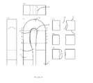
- FIG. 3 shows views of an aerofoil blade cooling passage having a bend geometry according to an embodiment of the present invention.
- the blade has facing wall parts 20, 22 that are interconnected by a generally longitudinally extending divider member 23 to partially define first 25 and second 27 cooling fluid passage portions disposed in side-by-side generally longitudinally extending relationship.
- the wall parts are formed by pressure and suction flanks of the aerofoil portion of the blade.
- the first and second passage portions are interconnected in series fluid flow relationship by a bend passage portion 29.
- the first passage portion is adapted to direct cooling fluid to the bend passage portion and the second passage portion is adapted to exhaust cooling fluid from the bend passage portion.
- the divider member 23 has a first local thickening 33 in the region of the bend portion to provide a localised contraction of the downstream end of the first passage portion.
- the first local thickening helps to accelerate the cooling fluid flow before it enters the bend passage portion. It also pre-turns the flow in the opposite sense to the turn of the bend passage portion.
- the divider member also has a second local thickening 31 in the region of the bend portion that provides a localised progressive series narrowing and opening of the upstream end of the second passage portion in the general direction of cooling fluid flow.
- the shading in Figures 3(a) and 3(b) shows the surface contouring of the divider member on respectively its bend passage portion surface and its first passage portion surface, the contouring arising from local variations in the thickness of the divider member.
- the surface of the divider member 23 may be considered as an inside bend wall connecting the wall parts 20, 22 along the first 25 and second 27 flow passage portions and forming the inside of the bend made by the bend passage portion 29, the first 33 and second 31 local thickenings forming respective local prominences on the inside bend wall.
- the divider member has a centre line 35 which runs along its surface, midway between the facing wall parts.
- the first local thickening 33 of the divider member is greater along the centre line of the divider member than along the edges of the divider member where it connects with the wall parts.
- the flow path is therefore contracted earlier in the region midway between the facing wall parts than in the region where the divider member meets the facing wall parts.
- the convex shape of the divider member surface at its centre line at the first local thickening eases the passage of the flow towards the facing wall parts, which reduces the strength of the secondary flows on those parts. Pre-turning the flow in the opposite sense to the turn of the bend passage portion also reduces a tendency for the flow to separate from the surface of the divider member after the bend due to an adverse pressure gradient at the centre line.
- Figure 4 shows how the contraction in the flow path varies throughout the course of the bend.
- the local variations in thickness of the divider member shape the inside walls of the passage portions, and cause the flow path to narrow to different extents depending on the lateral distance from the facing wall parts.
- the first local thickening of the divider member is greater along the centre line of the divider member than along the edges of the divider member where the divider member connects with the wall parts.
- Figure 4(d) shows how this causes a narrowing 37 of the flow path in the first fluid passage portion which is greater towards the centre line of the divider member than at the edges where the divider member connects with the wall parts.
- Figures 4(e) and 4(f) show cross sections taken through the cooling passage at distances further away from the bend than that shown in 4(d).
- the second local thickening of the divider member is reduced along the centre line of the divider member relative to along the edges where the divider member connects with the facing wall parts, and so the flow path in this portion of the second fluid passage portion is less narrowed towards the centre line of the divider member than at the edges where the divider member meets the facing wall parts.
- Figure 4(f) shows that further downstream in the second fluid passage portion, the second local thickening is reduced at the edges where the divider member meets the facing wall parts, and is greatest at positions between the centre line and these edges.
- Figure 4(f) shows how the second local thickening defines a pair of cusps 39 at the boundaries between the divider member and the facing wall parts in the second fluid passage portion.
- the cusps can interact with secondary flows which form on the wall portions and the inner surface of the bend in a way that reduces the extent of separated flow, i.e. the flow can be helped to remain attached to the inner wall, allowing it to be slowed down reversibly.
- Figure 5 shows a cross section through an aerofoil blade having a cooling path geometry according to the present invention.
- the fluid flows through the first fluid passage portion 25 and around a U-bend to return back through the second fluid passage portion 27.
- the dotted lines 33 and 31 indicate the outline of the respective first and second local thickenings of the divider member 23 that the fluid encounters as it circulates around the U-bend.
- the wall parts 20, 22 are respectively formed in this case by suction and pressure flanks of the aerofoil portion of the blade.
- the CFD predicted line and experimental points labelled "Friction Factor” are results for a reference straight passage of square cross-section. For this passage the correspondence between prediction and experiment was very good. The other results are for passages in which the first passage portion begins at the left hand end of the horizontal axis, the bend passage extends from about 30 to about 35 on the horizontal axis, and the second passage portion extends to the right hand end of the horizontal axis.
- the CFD predicted line and experimental points labelled "Datum” are results for a passage in which there were no local thickenings in the region of the bend portion.
- the CFD predicted line and experimental points labelled "Optimum 2D/Opt 2D” are results for a 2D passage in which there were local thickenings in the region of the bend portion according to the present invention.
- the CFD predicted line and experimental points labelled "Optimum 3D/Opt 3D” are results for a 3D passage in which there were local thickenings in the region of the bend portion according to the present invention.
- a fluid flow conduit can be provided having advantageous pressure-loss reducing features equivalent to those associated with a bend made by an interior passage of a rotor blade or vane of the present invention described above, but for use in other technical fields where tight (ie at least 90°) fluid flow turns have to be made.
Landscapes
- Engineering & Computer Science (AREA)
- Mechanical Engineering (AREA)
- General Engineering & Computer Science (AREA)
- Turbine Rotor Nozzle Sealing (AREA)
Applications Claiming Priority (1)
| Application Number | Priority Date | Filing Date | Title |
|---|---|---|---|
| GBGB0915680.3A GB0915680D0 (en) | 2009-09-09 | 2009-09-09 | Cooled aerofoil blade or vane |
Publications (3)
| Publication Number | Publication Date |
|---|---|
| EP2299058A2 true EP2299058A2 (fr) | 2011-03-23 |
| EP2299058A3 EP2299058A3 (fr) | 2013-10-16 |
| EP2299058B1 EP2299058B1 (fr) | 2015-10-07 |
Family
ID=41203375
Family Applications (1)
| Application Number | Title | Priority Date | Filing Date |
|---|---|---|---|
| EP10173689.0A Not-in-force EP2299058B1 (fr) | 2009-09-09 | 2010-08-23 | Aube profilée rotorique ou statorique et moteur à turbine à gaz associé |
Country Status (3)
| Country | Link |
|---|---|
| US (1) | US8662825B2 (fr) |
| EP (1) | EP2299058B1 (fr) |
| GB (1) | GB0915680D0 (fr) |
Cited By (1)
| Publication number | Priority date | Publication date | Assignee | Title |
|---|---|---|---|---|
| WO2019040272A1 (fr) * | 2017-08-24 | 2019-02-28 | Siemens Aktiengesellschaft | Profil aérodynamique de rotor de turbine et procédé correspondant pour la réduction de la perte de pression dans une cavité à l'intérieur d'une pale |
Families Citing this family (9)
| Publication number | Priority date | Publication date | Assignee | Title |
|---|---|---|---|---|
| US20140219813A1 (en) * | 2012-09-14 | 2014-08-07 | Rafael A. Perez | Gas turbine engine serpentine cooling passage |
| US9797258B2 (en) * | 2013-10-23 | 2017-10-24 | General Electric Company | Turbine bucket including cooling passage with turn |
| US9638041B2 (en) | 2013-10-23 | 2017-05-02 | General Electric Company | Turbine bucket having non-axisymmetric base contour |
| US9551226B2 (en) | 2013-10-23 | 2017-01-24 | General Electric Company | Turbine bucket with endwall contour and airfoil profile |
| US9528379B2 (en) | 2013-10-23 | 2016-12-27 | General Electric Company | Turbine bucket having serpentine core |
| US9670784B2 (en) | 2013-10-23 | 2017-06-06 | General Electric Company | Turbine bucket base having serpentine cooling passage with leading edge cooling |
| US10107108B2 (en) | 2015-04-29 | 2018-10-23 | General Electric Company | Rotor blade having a flared tip |
| US11000077B2 (en) * | 2017-07-10 | 2021-05-11 | ThermoBionics LLC | System, method, and apparatus for providing cooling |
| DE102018119572A1 (de) * | 2018-08-13 | 2020-02-13 | Man Energy Solutions Se | Kühlsystem zum aktiven Kühlen einer Turbinenschaufel |
Citations (1)
| Publication number | Priority date | Publication date | Assignee | Title |
|---|---|---|---|---|
| US5073086A (en) | 1990-07-03 | 1991-12-17 | Rolls-Royce Plc | Cooled aerofoil blade |
Family Cites Families (7)
| Publication number | Priority date | Publication date | Assignee | Title |
|---|---|---|---|---|
| US5536143A (en) * | 1995-03-31 | 1996-07-16 | General Electric Co. | Closed circuit steam cooled bucket |
| US6422817B1 (en) | 2000-01-13 | 2002-07-23 | General Electric Company | Cooling circuit for and method of cooling a gas turbine bucket |
| JP4064778B2 (ja) * | 2002-10-09 | 2008-03-19 | 三菱重工業株式会社 | ガスタービン翼体およびガスタービン |
| US7137780B2 (en) * | 2004-06-17 | 2006-11-21 | Siemens Power Generation, Inc. | Internal cooling system for a turbine blade |
| US7168921B2 (en) | 2004-11-18 | 2007-01-30 | General Electric Company | Cooling system for an airfoil |
| US7744347B2 (en) | 2005-11-08 | 2010-06-29 | United Technologies Corporation | Peripheral microcircuit serpentine cooling for turbine airfoils |
| US8591189B2 (en) | 2006-11-20 | 2013-11-26 | General Electric Company | Bifeed serpentine cooled blade |
-
2009
- 2009-09-09 GB GBGB0915680.3A patent/GB0915680D0/en not_active Ceased
-
2010
- 2010-08-23 EP EP10173689.0A patent/EP2299058B1/fr not_active Not-in-force
- 2010-08-23 US US12/861,560 patent/US8662825B2/en active Active
Patent Citations (1)
| Publication number | Priority date | Publication date | Assignee | Title |
|---|---|---|---|---|
| US5073086A (en) | 1990-07-03 | 1991-12-17 | Rolls-Royce Plc | Cooled aerofoil blade |
Cited By (2)
| Publication number | Priority date | Publication date | Assignee | Title |
|---|---|---|---|---|
| WO2019040272A1 (fr) * | 2017-08-24 | 2019-02-28 | Siemens Aktiengesellschaft | Profil aérodynamique de rotor de turbine et procédé correspondant pour la réduction de la perte de pression dans une cavité à l'intérieur d'une pale |
| US11111795B2 (en) | 2017-08-24 | 2021-09-07 | Siemens Energy Global GmbH & Co. KG | Turbine rotor airfoil and corresponding method for reducing pressure loss in a cavity within a blade |
Also Published As
| Publication number | Publication date |
|---|---|
| US20110058958A1 (en) | 2011-03-10 |
| US8662825B2 (en) | 2014-03-04 |
| EP2299058B1 (fr) | 2015-10-07 |
| EP2299058A3 (fr) | 2013-10-16 |
| GB0915680D0 (en) | 2009-10-07 |
Similar Documents
| Publication | Publication Date | Title |
|---|---|---|
| US8662825B2 (en) | Cooled aerofoil blade or vane | |
| JP6607566B2 (ja) | 空気冷却式のエンジン表面冷却器 | |
| EP2924239B1 (fr) | Aube de turbine et turbine á gaz | |
| US4714407A (en) | Aerofoil section members for turbine engines | |
| US5073086A (en) | Cooled aerofoil blade | |
| US11549393B2 (en) | Air-oil heat exchanger | |
| RU2711204C2 (ru) | Узел спрямления воздушного потока газотурбинного двигателя и газотурбинный двигатель, содержащий такой узел | |
| EP2725201A2 (fr) | Turbine à flux axial | |
| JP6435188B2 (ja) | タービン翼における構造的構成および冷却回路 | |
| EP3399149B1 (fr) | Couvercles de dérivation pour aubes dans des moteurs à turbine à gaz | |
| EP2103781B1 (fr) | Microcircuit de refroidissement de bord de fuite avec des sorties alternées convergentes | |
| EP2518269A2 (fr) | Aube de stator de turbine à gaz | |
| EP3336312A1 (fr) | Ensemble de refroidissement destiné à un ensemble turbine | |
| CN107152419A (zh) | 一种根部串联多段叶型的大弯折角压气机静子叶片 | |
| EP2518429A1 (fr) | Surface de refroidissement améliorée | |
| Joly et al. | Full design of a highly loaded fan by multi-objective optimization of through-flow and high-fidelity aero-mechanical performances | |
| CN113123832B (zh) | 用于冲击扰流气膜复合冷却的双层壁人字形扰流柱结构 | |
| CN108412555B (zh) | 阵列的凹腔射流改善叶顶泄漏流动及换热的涡轮动叶片 | |
| US10208604B2 (en) | Cooling features with three dimensional chevron geometry | |
| EP3163020B1 (fr) | Cascade de pales de rotor de turbine, étage de turbine et turbine à écoulement axial | |
| JP2014148938A (ja) | ターボ機械のためのフィルム冷却されるタービンブレード | |
| Andreoli et al. | Aerothermal optimization of fully cooled turbine blade tips | |
| JP5910461B2 (ja) | ターボチャージャー | |
| CN115045721B (zh) | 一种串联式旋流冲击涡轮叶片冷却单元及涡轮叶片 | |
| JP6397414B2 (ja) | 排気ガスターボチャージャ |
Legal Events
| Date | Code | Title | Description |
|---|---|---|---|
| PUAI | Public reference made under article 153(3) epc to a published international application that has entered the european phase |
Free format text: ORIGINAL CODE: 0009012 |
|
| AK | Designated contracting states |
Kind code of ref document: A2 Designated state(s): AL AT BE BG CH CY CZ DE DK EE ES FI FR GB GR HR HU IE IS IT LI LT LU LV MC MK MT NL NO PL PT RO SE SI SK SM TR |
|
| AX | Request for extension of the european patent |
Extension state: BA ME RS |
|
| PUAL | Search report despatched |
Free format text: ORIGINAL CODE: 0009013 |
|
| AK | Designated contracting states |
Kind code of ref document: A3 Designated state(s): AL AT BE BG CH CY CZ DE DK EE ES FI FR GB GR HR HU IE IS IT LI LT LU LV MC MK MT NL NO PL PT RO SE SI SK SM TR |
|
| AX | Request for extension of the european patent |
Extension state: BA ME RS |
|
| RIC1 | Information provided on ipc code assigned before grant |
Ipc: F01D 5/18 20060101AFI20130912BHEP |
|
| 17P | Request for examination filed |
Effective date: 20140416 |
|
| RBV | Designated contracting states (corrected) |
Designated state(s): AL AT BE BG CH CY CZ DE DK EE ES FI FR GB GR HR HU IE IS IT LI LT LU LV MC MK MT NL NO PL PT RO SE SI SK SM TR |
|
| RAP1 | Party data changed (applicant data changed or rights of an application transferred) |
Owner name: ROLLS-ROYCE PLC |
|
| GRAP | Despatch of communication of intention to grant a patent |
Free format text: ORIGINAL CODE: EPIDOSNIGR1 |
|
| GRAS | Grant fee paid |
Free format text: ORIGINAL CODE: EPIDOSNIGR3 |
|
| INTG | Intention to grant announced |
Effective date: 20150804 |
|
| GRAA | (expected) grant |
Free format text: ORIGINAL CODE: 0009210 |
|
| AK | Designated contracting states |
Kind code of ref document: B1 Designated state(s): AL AT BE BG CH CY CZ DE DK EE ES FI FR GB GR HR HU IE IS IT LI LT LU LV MC MK MT NL NO PL PT RO SE SI SK SM TR |
|
| REG | Reference to a national code |
Ref country code: GB Ref legal event code: FG4D |
|
| REG | Reference to a national code |
Ref country code: AT Ref legal event code: REF Ref document number: 753890 Country of ref document: AT Kind code of ref document: T Effective date: 20151015 Ref country code: CH Ref legal event code: EP |
|
| REG | Reference to a national code |
Ref country code: IE Ref legal event code: FG4D |
|
| REG | Reference to a national code |
Ref country code: DE Ref legal event code: R096 Ref document number: 602010028019 Country of ref document: DE |
|
| REG | Reference to a national code |
Ref country code: NL Ref legal event code: MP Effective date: 20151007 |
|
| REG | Reference to a national code |
Ref country code: AT Ref legal event code: MK05 Ref document number: 753890 Country of ref document: AT Kind code of ref document: T Effective date: 20151007 |
|
| REG | Reference to a national code |
Ref country code: LT Ref legal event code: MG4D |
|
| PG25 | Lapsed in a contracting state [announced via postgrant information from national office to epo] |
Ref country code: ES Free format text: LAPSE BECAUSE OF FAILURE TO SUBMIT A TRANSLATION OF THE DESCRIPTION OR TO PAY THE FEE WITHIN THE PRESCRIBED TIME-LIMIT Effective date: 20151007 Ref country code: IS Free format text: LAPSE BECAUSE OF FAILURE TO SUBMIT A TRANSLATION OF THE DESCRIPTION OR TO PAY THE FEE WITHIN THE PRESCRIBED TIME-LIMIT Effective date: 20160207 Ref country code: NO Free format text: LAPSE BECAUSE OF FAILURE TO SUBMIT A TRANSLATION OF THE DESCRIPTION OR TO PAY THE FEE WITHIN THE PRESCRIBED TIME-LIMIT Effective date: 20160107 Ref country code: IT Free format text: LAPSE BECAUSE OF FAILURE TO SUBMIT A TRANSLATION OF THE DESCRIPTION OR TO PAY THE FEE WITHIN THE PRESCRIBED TIME-LIMIT Effective date: 20151007 Ref country code: LT Free format text: LAPSE BECAUSE OF FAILURE TO SUBMIT A TRANSLATION OF THE DESCRIPTION OR TO PAY THE FEE WITHIN THE PRESCRIBED TIME-LIMIT Effective date: 20151007 Ref country code: HR Free format text: LAPSE BECAUSE OF FAILURE TO SUBMIT A TRANSLATION OF THE DESCRIPTION OR TO PAY THE FEE WITHIN THE PRESCRIBED TIME-LIMIT Effective date: 20151007 Ref country code: NL Free format text: LAPSE BECAUSE OF FAILURE TO SUBMIT A TRANSLATION OF THE DESCRIPTION OR TO PAY THE FEE WITHIN THE PRESCRIBED TIME-LIMIT Effective date: 20151007 |
|
| REG | Reference to a national code |
Ref country code: DE Ref legal event code: R082 Ref document number: 602010028019 Country of ref document: DE Representative=s name: HERNANDEZ, YORCK, DIPL.-ING., DE |
|
| PG25 | Lapsed in a contracting state [announced via postgrant information from national office to epo] |
Ref country code: LV Free format text: LAPSE BECAUSE OF FAILURE TO SUBMIT A TRANSLATION OF THE DESCRIPTION OR TO PAY THE FEE WITHIN THE PRESCRIBED TIME-LIMIT Effective date: 20151007 Ref country code: FI Free format text: LAPSE BECAUSE OF FAILURE TO SUBMIT A TRANSLATION OF THE DESCRIPTION OR TO PAY THE FEE WITHIN THE PRESCRIBED TIME-LIMIT Effective date: 20151007 Ref country code: SE Free format text: LAPSE BECAUSE OF FAILURE TO SUBMIT A TRANSLATION OF THE DESCRIPTION OR TO PAY THE FEE WITHIN THE PRESCRIBED TIME-LIMIT Effective date: 20151007 Ref country code: PL Free format text: LAPSE BECAUSE OF FAILURE TO SUBMIT A TRANSLATION OF THE DESCRIPTION OR TO PAY THE FEE WITHIN THE PRESCRIBED TIME-LIMIT Effective date: 20151007 Ref country code: PT Free format text: LAPSE BECAUSE OF FAILURE TO SUBMIT A TRANSLATION OF THE DESCRIPTION OR TO PAY THE FEE WITHIN THE PRESCRIBED TIME-LIMIT Effective date: 20160208 Ref country code: AT Free format text: LAPSE BECAUSE OF FAILURE TO SUBMIT A TRANSLATION OF THE DESCRIPTION OR TO PAY THE FEE WITHIN THE PRESCRIBED TIME-LIMIT Effective date: 20151007 Ref country code: GR Free format text: LAPSE BECAUSE OF FAILURE TO SUBMIT A TRANSLATION OF THE DESCRIPTION OR TO PAY THE FEE WITHIN THE PRESCRIBED TIME-LIMIT Effective date: 20160108 |
|
| REG | Reference to a national code |
Ref country code: DE Ref legal event code: R097 Ref document number: 602010028019 Country of ref document: DE |
|
| PG25 | Lapsed in a contracting state [announced via postgrant information from national office to epo] |
Ref country code: CZ Free format text: LAPSE BECAUSE OF FAILURE TO SUBMIT A TRANSLATION OF THE DESCRIPTION OR TO PAY THE FEE WITHIN THE PRESCRIBED TIME-LIMIT Effective date: 20151007 |
|
| PLBE | No opposition filed within time limit |
Free format text: ORIGINAL CODE: 0009261 |
|
| STAA | Information on the status of an ep patent application or granted ep patent |
Free format text: STATUS: NO OPPOSITION FILED WITHIN TIME LIMIT |
|
| REG | Reference to a national code |
Ref country code: FR Ref legal event code: PLFP Year of fee payment: 7 |
|
| PG25 | Lapsed in a contracting state [announced via postgrant information from national office to epo] |
Ref country code: RO Free format text: LAPSE BECAUSE OF FAILURE TO SUBMIT A TRANSLATION OF THE DESCRIPTION OR TO PAY THE FEE WITHIN THE PRESCRIBED TIME-LIMIT Effective date: 20151007 Ref country code: SK Free format text: LAPSE BECAUSE OF FAILURE TO SUBMIT A TRANSLATION OF THE DESCRIPTION OR TO PAY THE FEE WITHIN THE PRESCRIBED TIME-LIMIT Effective date: 20151007 Ref country code: DK Free format text: LAPSE BECAUSE OF FAILURE TO SUBMIT A TRANSLATION OF THE DESCRIPTION OR TO PAY THE FEE WITHIN THE PRESCRIBED TIME-LIMIT Effective date: 20151007 Ref country code: SM Free format text: LAPSE BECAUSE OF FAILURE TO SUBMIT A TRANSLATION OF THE DESCRIPTION OR TO PAY THE FEE WITHIN THE PRESCRIBED TIME-LIMIT Effective date: 20151007 Ref country code: EE Free format text: LAPSE BECAUSE OF FAILURE TO SUBMIT A TRANSLATION OF THE DESCRIPTION OR TO PAY THE FEE WITHIN THE PRESCRIBED TIME-LIMIT Effective date: 20151007 |
|
| 26N | No opposition filed |
Effective date: 20160708 |
|
| PG25 | Lapsed in a contracting state [announced via postgrant information from national office to epo] |
Ref country code: SI Free format text: LAPSE BECAUSE OF FAILURE TO SUBMIT A TRANSLATION OF THE DESCRIPTION OR TO PAY THE FEE WITHIN THE PRESCRIBED TIME-LIMIT Effective date: 20151007 |
|
| PG25 | Lapsed in a contracting state [announced via postgrant information from national office to epo] |
Ref country code: BE Free format text: LAPSE BECAUSE OF FAILURE TO SUBMIT A TRANSLATION OF THE DESCRIPTION OR TO PAY THE FEE WITHIN THE PRESCRIBED TIME-LIMIT Effective date: 20151007 |
|
| PG25 | Lapsed in a contracting state [announced via postgrant information from national office to epo] |
Ref country code: MC Free format text: LAPSE BECAUSE OF FAILURE TO SUBMIT A TRANSLATION OF THE DESCRIPTION OR TO PAY THE FEE WITHIN THE PRESCRIBED TIME-LIMIT Effective date: 20151007 |
|
| REG | Reference to a national code |
Ref country code: CH Ref legal event code: PL |
|
| PG25 | Lapsed in a contracting state [announced via postgrant information from national office to epo] |
Ref country code: LI Free format text: LAPSE BECAUSE OF NON-PAYMENT OF DUE FEES Effective date: 20160831 Ref country code: CH Free format text: LAPSE BECAUSE OF NON-PAYMENT OF DUE FEES Effective date: 20160831 |
|
| REG | Reference to a national code |
Ref country code: IE Ref legal event code: MM4A |
|
| PG25 | Lapsed in a contracting state [announced via postgrant information from national office to epo] |
Ref country code: IE Free format text: LAPSE BECAUSE OF NON-PAYMENT OF DUE FEES Effective date: 20160823 |
|
| REG | Reference to a national code |
Ref country code: FR Ref legal event code: PLFP Year of fee payment: 8 |
|
| PG25 | Lapsed in a contracting state [announced via postgrant information from national office to epo] |
Ref country code: LU Free format text: LAPSE BECAUSE OF NON-PAYMENT OF DUE FEES Effective date: 20160823 |
|
| PGFP | Annual fee paid to national office [announced via postgrant information from national office to epo] |
Ref country code: GB Payment date: 20170829 Year of fee payment: 8 Ref country code: DE Payment date: 20170829 Year of fee payment: 8 Ref country code: FR Payment date: 20170825 Year of fee payment: 8 |
|
| PG25 | Lapsed in a contracting state [announced via postgrant information from national office to epo] |
Ref country code: CY Free format text: LAPSE BECAUSE OF FAILURE TO SUBMIT A TRANSLATION OF THE DESCRIPTION OR TO PAY THE FEE WITHIN THE PRESCRIBED TIME-LIMIT Effective date: 20151007 Ref country code: HU Free format text: LAPSE BECAUSE OF FAILURE TO SUBMIT A TRANSLATION OF THE DESCRIPTION OR TO PAY THE FEE WITHIN THE PRESCRIBED TIME-LIMIT; INVALID AB INITIO Effective date: 20100823 |
|
| PG25 | Lapsed in a contracting state [announced via postgrant information from national office to epo] |
Ref country code: MK Free format text: LAPSE BECAUSE OF FAILURE TO SUBMIT A TRANSLATION OF THE DESCRIPTION OR TO PAY THE FEE WITHIN THE PRESCRIBED TIME-LIMIT Effective date: 20151007 Ref country code: MT Free format text: LAPSE BECAUSE OF NON-PAYMENT OF DUE FEES Effective date: 20160831 Ref country code: TR Free format text: LAPSE BECAUSE OF FAILURE TO SUBMIT A TRANSLATION OF THE DESCRIPTION OR TO PAY THE FEE WITHIN THE PRESCRIBED TIME-LIMIT Effective date: 20151007 |
|
| PG25 | Lapsed in a contracting state [announced via postgrant information from national office to epo] |
Ref country code: BG Free format text: LAPSE BECAUSE OF FAILURE TO SUBMIT A TRANSLATION OF THE DESCRIPTION OR TO PAY THE FEE WITHIN THE PRESCRIBED TIME-LIMIT Effective date: 20151007 |
|
| PG25 | Lapsed in a contracting state [announced via postgrant information from national office to epo] |
Ref country code: AL Free format text: LAPSE BECAUSE OF FAILURE TO SUBMIT A TRANSLATION OF THE DESCRIPTION OR TO PAY THE FEE WITHIN THE PRESCRIBED TIME-LIMIT Effective date: 20151007 |
|
| REG | Reference to a national code |
Ref country code: DE Ref legal event code: R119 Ref document number: 602010028019 Country of ref document: DE |
|
| GBPC | Gb: european patent ceased through non-payment of renewal fee |
Effective date: 20180823 |
|
| PG25 | Lapsed in a contracting state [announced via postgrant information from national office to epo] |
Ref country code: DE Free format text: LAPSE BECAUSE OF NON-PAYMENT OF DUE FEES Effective date: 20190301 |
|
| PG25 | Lapsed in a contracting state [announced via postgrant information from national office to epo] |
Ref country code: FR Free format text: LAPSE BECAUSE OF NON-PAYMENT OF DUE FEES Effective date: 20180831 |
|
| PG25 | Lapsed in a contracting state [announced via postgrant information from national office to epo] |
Ref country code: GB Free format text: LAPSE BECAUSE OF NON-PAYMENT OF DUE FEES Effective date: 20180823 |