EP2299092A2 - Luftteilchentrenner für einen Gasturbinenmotor - Google Patents
Luftteilchentrenner für einen Gasturbinenmotor Download PDFInfo
- Publication number
- EP2299092A2 EP2299092A2 EP20100251537 EP10251537A EP2299092A2 EP 2299092 A2 EP2299092 A2 EP 2299092A2 EP 20100251537 EP20100251537 EP 20100251537 EP 10251537 A EP10251537 A EP 10251537A EP 2299092 A2 EP2299092 A2 EP 2299092A2
- Authority
- EP
- European Patent Office
- Prior art keywords
- baffle
- bearing compartment
- seal
- debris
- assembly
- Prior art date
- Legal status (The legal status is an assumption and is not a legal conclusion. Google has not performed a legal analysis and makes no representation as to the accuracy of the status listed.)
- Granted
Links
Images
Classifications
-
- F—MECHANICAL ENGINEERING; LIGHTING; HEATING; WEAPONS; BLASTING
- F02—COMBUSTION ENGINES; HOT-GAS OR COMBUSTION-PRODUCT ENGINE PLANTS
- F02C—GAS-TURBINE PLANTS; AIR INTAKES FOR JET-PROPULSION PLANTS; CONTROLLING FUEL SUPPLY IN AIR-BREATHING JET-PROPULSION PLANTS
- F02C7/00—Features, components parts, details or accessories, not provided for in, or of interest apart form groups F02C1/00 - F02C6/00; Air intakes for jet-propulsion plants
- F02C7/04—Air intakes for gas-turbine plants or jet-propulsion plants
- F02C7/05—Air intakes for gas-turbine plants or jet-propulsion plants having provisions for obviating the penetration of damaging objects or particles
- F02C7/052—Air intakes for gas-turbine plants or jet-propulsion plants having provisions for obviating the penetration of damaging objects or particles with dust-separation devices
-
- F—MECHANICAL ENGINEERING; LIGHTING; HEATING; WEAPONS; BLASTING
- F05—INDEXING SCHEMES RELATING TO ENGINES OR PUMPS IN VARIOUS SUBCLASSES OF CLASSES F01-F04
- F05D—INDEXING SCHEME FOR ASPECTS RELATING TO NON-POSITIVE-DISPLACEMENT MACHINES OR ENGINES, GAS-TURBINES OR JET-PROPULSION PLANTS
- F05D2240/00—Components
- F05D2240/10—Stators
- F05D2240/12—Fluid guiding means, e.g. vanes
- F05D2240/126—Baffles or ribs
Definitions
- the present invention relates to gas turbine engines, and more particularly, to bearing compartments in gas turbine engines.
- the rotating shafts and other rotating turbomachinery of gas turbine engines are supported from a non-rotating structure by arrays of anti-friction bearings.
- the anti-friction bearings are enclosed in bearing compartments that are in part bounded by an outer wall circumscribing the engine shafts.
- a lubricant such as oil is supplied to the bearing compartments to lubricate and cool the anti-friction bearings during operation of the gas turbine engine.
- the bearing compartments are sealed to protect the anti-friction bearings from debris introduced into the gas turbine engine and to restrict the lubricant from entering undesired areas of the engine.
- carbon seals are commonly used.
- a high pressure buffer air (also called pressurization air) flow is commonly supplied to the bearing compartments through the seals from sources within the gas turbine engine such as the compressor section. The buffer air aids in restricting the lubricant to bearing compartments.
- the high pressure buffer air flow is also used for other purposes including providing a nose cap of an engine fan with anti-icing heat.
- an additional seal must be positioned upstream of each bearing compartment seal to create a sufficient back pressure to induce flow.
- the upstream seal has been known to generate debris that can be introduced into the bearing compartment seal causing its premature failure.
- An assembly for separating debris from a pressurization air flow adjacent to a bearing compartment seal includes a baffle and a capture annulus.
- the baffle is disposed in the pressurization air flow upstream of the compartment seal.
- the capture annulus is positioned adjacent the baffle and has a cavity to collect the debris.
- a method for separating debris from a pressurization air flow adjacent a bearing compartment seal comprises directing the pressurization air stream around a baffle disposed upstream of the bearing compartment seal, and capturing the debris in a cavity of a member disposed adjacent the baffle.
- a gas turbine engine comprising a bearing compartment mounted within the gas turbine engine, the bearing compartment including a bearing compartment seal that is operably supplied with a pressurization air flow, a shaft rotatably mounted within the gas turbine engine adjacent the bearing compartment, the shaft having a baffle positioned in the pressurization air flow upstream of the compartment seal and a capture annulus disposed adjacent the baffle and having a cavity to collect the debris.
- the present application describes a method and a baffle and capture annulus assembly for separating debris from buffer or pressurization air flow adjacent a bearing compartment seal.
- the baffle and capture annulus assembly utilizes baffle separation and/or cyclonic or centrifugal separation to allow the debris to be removed and captured from the buffer air flow leaving a cleaner buffer air flow to contact the bearing compartment seal.
- the baffle is disposed in the pressurization air flow upstream (as defined by the direction of flow of the pressurization air) of the bearing compartment seal.
- the capture annulus is disposed adjacent the baffle and has a cavity to collect the debris.
- the capture annulus can include channels that extend through the capture annulus to allow for evacuation of the debris from the cavity to a buffer air supply plenum away from the bearing compartment seal. In this manner, cleaner pressurization air is supplied to the bearing compartment seal and to the bearing compartment within the gas turbine engine. The cleaner buffer air flow helps to reduce the rate of premature failure of the bearing compartment seal.
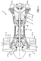
- FIG. 1 shows a schematic cross section of a gas turbine engine 10 in which bearing compartments 12A and 12B are used to house anti-friction bearings 14A and 14B that support shafts 16A and 16B.
- the gas turbine engine 10 is schematically shown with only two shafts 16A and 16B rather than several shafts.
- the gas turbine engine 10 can comprise a high bypass ratio turbofan engine or another type of gas turbine engine used for aircraft propulsion or power generation.
- the gas turbine engine 10 includes a fan 18, a low pressure compressor (LPC) 20, a high pressure compressor (HPC) 22, a combustor section 24, a high pressure turbine (HPT) 26 and a low pressure turbine (LPT) 28, which are each concentrically disposed around an axial engine centerline CL.
- the fan 18, the LPC 20, the HPC 22, the HPT 26, the LPT 28 and other engine components are enclosed at their outer diameters within various engine casings, including a fan case 30 and a LPC case 32.
- the fan 18 and the LPC 20 are connected to LPT 28 through shaft 16A, which is supported by the anti-friction bearings 14A.
- the anti-friction bearings 14A are housed within bearing compartments 12A.
- lubricant is fed into the bearing compartments 12A and 12B from other portions of the engine 10.
- the fan 18, the LPC 20, the LPT 28 and the shaft 16A comprise the low pressure spool.
- the HPC 22 is connected to the HPT 26 through shaft 16B, which is supported within engine 10 by anti-friction bearings 14B housed in the bearing compartments 12B. Together, the HPC 22, the HPT 26 and the shaft 16B comprise the high pressure spool.
- Inlet air A enters engine 10 whereby it is divided into streams of a primary air A P and a secondary air As after passing through the fan 18.
- the fan 18 is rotated by the low pressure turbine 26 through the shaft 16A to accelerate the secondary air A S (also known as bypass air) through exit guide vanes 34, thereby producing a significant portion of the thrust output of engine 10.
- the primary air A P also known as gas path air
- the LPC 20 and the HPC 22 work together to incrementally increase the pressure and temperature of primary air A P .
- High pressure buffer air A b (also known as pressurization air) is bled off one or more of the stages of the LPC 20 or HPC 22 and is supplied to the bearing compartments 12A and 12B. Buffer air A b is also supplied to other components of the engine 10 for anti-icing purposes and to remove debris from engine 10.
- HPC 22 is rotated by HPT 26 through shaft 16B to provide compressed air to combustor section 24.
- the compressed air is delivered to combustor 24, along with fuel from the injectors, such that a combustion process can be carried out to produce high energy gases necessary to turn high pressure turbine 26 and low pressure turbine 28.
- Primary air A P continues through gas turbine engine 10 whereby it is typically passed through an exhaust nozzle to further produce thrust.
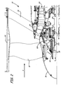
- FIG. 2 shows a forward section of the gas turbine engine 10 above centerline CL ( FIG. 1 ).
- the engine 10 includes a fan nose 36, bearing compartment seals 38, a fan hub 40 and an epicyclic gear assembly 42.
- the bearing compartment 12A shown in FIG. 2 is disposed in a forward portion of the gas turbine engine 10 adjacent the fan 18 and fan nose 36.
- the buffer air A b and lubricating oil are supplied to the bearing compartment 12A.
- the oil lubricates the anti-friction bearings 14A and an interior portion of the bearing compartment seals 38.
- the buffer air A b is initially supplied to the exterior portion of the bearing compartment seals 38 along an air flow path.
- a pressure differential between the interior of the bearing compartment 12A and the buffer air A b along with the configuration of the bearing compartment seals 38 allows the buffer air A b to migrate across the bearing compartment seals 38 into the bearing compartment 12A.
- the operation and configuration of similar bearing compartments and bearing compartment seals are further detailed in U.S. Patent Nos. 7,287,384 and 4,709,545 .
- the buffer air A b is also directed to the fan nose 36 to provide anti-icing heat to that feature.
- the bearing compartment 12A is stationarily mounted within the gas turbine engine 10 adjacent the rotating fan hub 40.
- the epicyclic gear assembly 42 transfers rotation from one of the shafts within the gas turbine engine 10 to other turbomachinery including the rotating fan hub 40 (a shaft).
- the fan hub 40 has a baffle (not shown) and the bearing compartment 12A has a capture annulus (not shown).
- the baffle and capture annulus are disposed upstream (as defined by the direction of flow of the buffer air A b ) of the bearing compartment seals 38 and are configured to separate debris from the buffer air A b prior to the buffer air A b reaching the bearing compartment seals 38.
- the separated debris is then evacuated away from the bearing compartment 12A and is carried by a portion of the buffer air A b into either the anti-icing flow or to other portions of the gas turbine engine 10 before eventually being expelled from the engine 10 altogether.
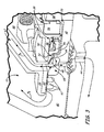
- FIG. 3 shows a perspective cross-sectional view of a forward portion of the bearing compartment 12A and also illustrates the bearing compartment seals 38.
- the bearing compartment 12A includes a seal housing 44, a seal carrier 46, and a capture annulus 48 having a cavity or trench 50 and channel 52.
- the bearing compartment seals 38 include a secondary seal 54, a carbon seal 56, and a seal plate 58.
- An abradable seal land 60 is disposed between the seal housing 44 and the fan hub 40.
- the fan hub 40 includes a labyrinth plate seal 62, a baffle or rib 64, and an anti-icing air supply hole 66.
- the stationary bearing compartment 12A is disposed within the gas turbine engine 10 ( FIGS. 1 and 2 ) adjacent the rotating fan hub 40.
- the seal housing 44 comprises a forward portion of the bearing compartment 12A.
- the seal housing 44 is bolted to an open side of the bearing compartment 12A and holds at least one of the bearing compartment seals 38.
- the seal carrier 46 is partially disposed within the seal housing 44.
- the radially inner portion of the seal housing 44 adjacent the seal carrier 46 comprises the capture annulus 48.
- the trench 50 extends generally radially inward into the capture annulus 48.
- the capture annulus 48 and trench 50 extend arcuately adjacent the fan hub 40.
- the channel 52 (in one embodiment a plurality of about 15 to 50 channels) extends through the capture annulus 48 to communicate with the cavity 50.
- the number and diameter of the channels can very depending on design criteria such as the model of turbine engine utilized.
- the seal housing 44 and seal carrier 46 support the secondary seal 54 therebetween.
- the secondary seal 54 is one of the bearing compartment seals 38.
- the seal carrier 46 connects to the carbon seal 56 and helps to keep the carbon seal 56 in contact with the seal plate 58.
- the seal housing 44 defines a buffer air supply channel 67 that allows the flow of buffer air A b into a buffer air supply cavity 68 adjacent the seal housing 44 and the fan hub 40. From the buffer air supply cavity 68 the buffer air A b can communicate with and become the anti-icing air flow and can also communicate (through a passage 70 between the seal housing 44 and the fan hub 40) with the secondary seal 54, the carbon seal 56, and the seal plate 58 (together collectively the bearing compartment seals 38).
- the anti-icing air supply hole 66 in one embodiment a plurality of anti-icing holes 66 are utilized to allow for communication between the fan nose 36 ( FIG. 2 ) and the buffer air supply cavity 68. During operation a portion of the buffer air A b enters the anti-icing holes 66 and is sent to the fan nose 36 ( FIG. 2 ) to perform anti-icing functions. After performing these functions the air is then expelled from the gas turbine engine 10.
- a forward portion of the seal housing 44 is adapted with a flange that receives the abradable seal land 60.
- the abradable seal land 60 is disposed adjacent the labyrinth plate seal 62 upstream (as defined by the direction of buffer air A b flow) of the secondary seal 54, the carbon seal 56, and the seal plate 58. Together the abradable seal land 60 and the labyrinth plate seal 62 create a back pressure sufficient to generate the buffer air A b flow for anti-icing and sealing.
- the baffle 64 extends radially outward from and is integral with the fan hub 40. The baffle 64 is disposed along passage 70 such that it is positioned in the buffer air A b flow upstream (as defined by the direction of buffer air A b flow) of the secondary seal 54, the carbon seal 56, and the seal plate 58.
- the seal housing 44 is hollow and arcuate in shape and separates the lubrication fluid from the buffer air A b entering the buffer air supply cavity 68.
- the secondary seal 54 disposed between the seal housing 44 and seal carrier 46, is configured to create a lubricant seal in the forward and aft directions.
- the outwardly radial portions (interior portion of the bearing compartment 12A) of the seal carrier 46, the carbon seal 56, and the seal plate 58 are similarly wetted by lubricant.
- the carbon seal 56 rubs against the rotating seal plate 58 and seals the lubricant within the bearing compartment 12A.
- the seal plate 58 and carbon seal 56 are configured to allow as small amount of "cleaner" buffer air A bc into the bearing compartment 12A to aid in the prevention of lubricant leakage out of the bearing compartment 12A.
- the buffer air A b which may contain debris, flows into the buffer air supply cavity 68 from the buffer air supply channel 67. From the buffer air supply cavity 68, a portion of the buffer air A b communicates between the abradable seal land 60 and the labyrinth plate seal 62 which provide backpressure to the system. Some portion of the buffer air A b passes across the abradable seal land 60 and the labyrinth plate seal 62 away from the buffer air supply cavity 68 and enters an outer cavity 72 before being expelled from the gas turbine engine 10 ( FIGS. 1 and 2 ). In some instances, the abradable seal land 60 and the rotating labyrinth plate seal 62 can introduce debris into the buffer air A b .
- This debris enters the buffer air supply cavity 68 upstream of the bearing compartment seals 38. From the buffer air supply cavity 68, a portion of the buffer air A b flows toward the passage 70 and encounters the rotating baffle 64, which is positioned in the flow path of the buffer air A b upstream of the bearing compartment seals 38.
- the annular baffle 64 is disposed adjacent the capture annulus 48, and in particular, is disposed radially inward of the cavity 50.
- the baffle 64 is shaped to direct the debris laden buffer air A b flow radially upward away from the baffle 64 toward the capture annulus 48 and cavity 50.
- the shape of the baffle 64 and the direction of the flow toward the bearing compartment seals 38 then forces the debris laden buffer air A b to make a sharp turn (in the embodiment shown a turn of about 90 degrees).
- the larger inertia of the debris does not allow the debris to make this turn.
- the debris continues along a flow path into the cavity 50 that is separate from that of the cleaner buffer air A bc which continues on to passage 70 and the bearing compartment seals 38.
- the rotation of the baffle 64 relative to the debris laden buffer air A b flow energizes and accelerates the buffer air A b to induce a swirl or rotation therein.
- the centrifugal forces resulting from the rotation of the buffer air A b flow push the heavier debris radially away from the rotating baffle 64.
- the debris is centrifuged radially outward from the baffle 64 into the cavity 50 where it is captured.
- the cavity 50 captures the debris, and holds it separate from the cleaner buffer air A bc flow which continues around baffle 64 to passage 70 and the bearing compartment seals 38.
- the cavity 50 is configured to extend radially inward into the capture annulus 48 and axially forward and aft of the baffle 64 to a sufficient distance to allow the debris captured within the cavity 50 to be substantially outside of the flow path of the cleaner buffer air A bc stream. In one embodiment, this is achieved by configuring the radial depth of the cavity 50 to have a ratio of about 1:1 when compared to the radial height of the baffle 64. In other embodiments, the ratio of the radial depth of the cavity 50 to the radial height of the baffle 64 can be greater or less than 1:1 depending on design criteria, for example, the rate of flow of the buffer air A b .
- the channel 52 extends through the capture annulus 48 forward of the baffle 64 to allow for evacuation and re-circulation of the debris from the cavity 50 to the buffer air supply plenum 68. From the buffer air supply plenum 68 the re-circulated debris enters the anti-icing flow or crosses the seal land 60 and the labyrinth plate seal 62, and in either instance, is eventually expelled from the gas turbine engine 10 ( FIGS. 1 and 2 ).
Landscapes
- Engineering & Computer Science (AREA)
- Chemical & Material Sciences (AREA)
- Combustion & Propulsion (AREA)
- Mechanical Engineering (AREA)
- General Engineering & Computer Science (AREA)
- Sealing Using Fluids, Sealing Without Contact, And Removal Of Oil (AREA)
- Turbine Rotor Nozzle Sealing (AREA)
- Cyclones (AREA)
Applications Claiming Priority (1)
| Application Number | Priority Date | Filing Date | Title |
|---|---|---|---|
| US12/552,490 US8561411B2 (en) | 2009-09-02 | 2009-09-02 | Air particle separator for a gas turbine engine |
Publications (3)
| Publication Number | Publication Date |
|---|---|
| EP2299092A2 true EP2299092A2 (de) | 2011-03-23 |
| EP2299092A3 EP2299092A3 (de) | 2014-10-29 |
| EP2299092B1 EP2299092B1 (de) | 2020-01-22 |
Family
ID=43231147
Family Applications (1)
| Application Number | Title | Priority Date | Filing Date |
|---|---|---|---|
| EP10251537.6A Active EP2299092B1 (de) | 2009-09-02 | 2010-09-01 | Luftteilchentrenner für einen Gasturbinenmotor |
Country Status (2)
| Country | Link |
|---|---|
| US (1) | US8561411B2 (de) |
| EP (1) | EP2299092B1 (de) |
Cited By (6)
| Publication number | Priority date | Publication date | Assignee | Title |
|---|---|---|---|---|
| JP2013108500A (ja) * | 2011-11-23 | 2013-06-06 | United Technologies Corp <Utc> | ガスタービンエンジン |
| EP2325458A3 (de) * | 2009-11-20 | 2014-01-08 | United Technologies Corporation | Balgvorladung und Zentrierschraube für ein Lüfterantriebsgetriebesystem |
| US9163522B2 (en) | 2012-08-21 | 2015-10-20 | United Technologies Corporation | Spring carrier and removable seal carrier |
| WO2015181326A1 (en) * | 2014-05-30 | 2015-12-03 | Nuovo Pignone Srl | Sealing device for turbomachines |
| US9784181B2 (en) | 2009-11-20 | 2017-10-10 | United Technologies Corporation | Gas turbine engine architecture with low pressure compressor hub between high and low rotor thrust bearings |
| FR3062679A1 (fr) * | 2017-02-07 | 2018-08-10 | Safran Aircraft Engines | Virole de reduction de la surpression au voisinage du joint amont d'une enceinte de palier de turboreacteur |
Families Citing this family (38)
| Publication number | Priority date | Publication date | Assignee | Title |
|---|---|---|---|---|
| US10286407B2 (en) | 2007-11-29 | 2019-05-14 | General Electric Company | Inertial separator |
| US8777793B2 (en) | 2011-04-27 | 2014-07-15 | United Technologies Corporation | Fan drive planetary gear system integrated carrier and torque frame |
| US10400629B2 (en) | 2012-01-31 | 2019-09-03 | United Technologies Corporation | Gas turbine engine shaft bearing configuration |
| US8863491B2 (en) | 2012-01-31 | 2014-10-21 | United Technologies Corporation | Gas turbine engine shaft bearing configuration |
| US9038366B2 (en) | 2012-01-31 | 2015-05-26 | United Technologies Corporation | LPC flowpath shape with gas turbine engine shaft bearing configuration |
| US10415468B2 (en) | 2012-01-31 | 2019-09-17 | United Technologies Corporation | Gas turbine engine buffer system |
| US10502135B2 (en) | 2012-01-31 | 2019-12-10 | United Technologies Corporation | Buffer system for communicating one or more buffer supply airs throughout a gas turbine engine |
| US10018116B2 (en) | 2012-01-31 | 2018-07-10 | United Technologies Corporation | Gas turbine engine buffer system providing zoned ventilation |
| US9309775B2 (en) * | 2012-05-21 | 2016-04-12 | United Technologies Corporation | Rotational debris discourager for gas turbine engine bearing |
| US20140140824A1 (en) * | 2012-10-26 | 2014-05-22 | United Technologies Corporation | Oil system bearing compartment architecture for gas turbine engine |
| US9353685B2 (en) | 2012-12-21 | 2016-05-31 | United Technologies Corporation | Turbine engine nosecone with deformation region |
| US10823058B2 (en) | 2013-01-29 | 2020-11-03 | Raytheon Technologies Corporation | Thermoplastic nosecone for a turbine engine |
| US10145302B2 (en) * | 2013-03-04 | 2018-12-04 | United Technologies Corporation | Gas turbine engine lubrication system |
| US9067163B2 (en) | 2013-04-26 | 2015-06-30 | Hamilton Sundstrand Corporation | Particle separator |
| US9272293B2 (en) | 2013-04-29 | 2016-03-01 | Hamilton Sundstrand Corporation | Particle separator |
| DE102013213517A1 (de) | 2013-07-10 | 2015-01-15 | Rolls-Royce Deutschland Ltd & Co Kg | Flugtriebwerk |
| US9915176B2 (en) | 2014-05-29 | 2018-03-13 | General Electric Company | Shroud assembly for turbine engine |
| US11033845B2 (en) | 2014-05-29 | 2021-06-15 | General Electric Company | Turbine engine and particle separators therefore |
| WO2016032585A2 (en) | 2014-05-29 | 2016-03-03 | General Electric Company | Turbine engine, components, and methods of cooling same |
| WO2016025056A2 (en) | 2014-05-29 | 2016-02-18 | General Electric Company | Turbine engine and particle separators therefore |
| US10036319B2 (en) | 2014-10-31 | 2018-07-31 | General Electric Company | Separator assembly for a gas turbine engine |
| US10167725B2 (en) | 2014-10-31 | 2019-01-01 | General Electric Company | Engine component for a turbine engine |
| US9777642B2 (en) | 2014-11-21 | 2017-10-03 | General Electric Company | Gas turbine engine and method of assembling the same |
| US9897006B2 (en) | 2015-06-15 | 2018-02-20 | General Electric Company | Hot gas path component cooling system having a particle collection chamber |
| US9828915B2 (en) | 2015-06-15 | 2017-11-28 | General Electric Company | Hot gas path component having near wall cooling features |
| US9938899B2 (en) | 2015-06-15 | 2018-04-10 | General Electric Company | Hot gas path component having cast-in features for near wall cooling |
| US9970302B2 (en) | 2015-06-15 | 2018-05-15 | General Electric Company | Hot gas path component trailing edge having near wall cooling features |
| US10012147B2 (en) | 2015-08-17 | 2018-07-03 | United Technologies Corporation | Apparatus and method for air particle separator in gas turbine engine |
| US10835848B2 (en) | 2015-09-21 | 2020-11-17 | Raytheon Technologies Corporation | Apparatus and method for air particle capture in a gas turbine engine |
| US10202903B2 (en) | 2015-09-22 | 2019-02-12 | United Technologies Corporation | Apparatus and method for air particle separation in a gas turbine engine |
| US9988936B2 (en) | 2015-10-15 | 2018-06-05 | General Electric Company | Shroud assembly for a gas turbine engine |
| US10428664B2 (en) | 2015-10-15 | 2019-10-01 | General Electric Company | Nozzle for a gas turbine engine |
| US10724436B2 (en) | 2016-01-21 | 2020-07-28 | General Electric Company | Inlet particle separator for a turbine engine |
| US10400670B2 (en) | 2016-06-15 | 2019-09-03 | General Electric Company | Inlet particle separator for a turbine engine |
| US10704425B2 (en) | 2016-07-14 | 2020-07-07 | General Electric Company | Assembly for a gas turbine engine |
| US10695704B2 (en) | 2016-07-20 | 2020-06-30 | General Electric Company | Multi-station debris separation system |
| US10830138B2 (en) | 2016-07-20 | 2020-11-10 | General Electric Company | Fine debris multi-stage separation system |
| US10400795B2 (en) | 2016-07-20 | 2019-09-03 | General Electric Company | High pressure cyclonic separator for turbomachinery |
Citations (2)
| Publication number | Priority date | Publication date | Assignee | Title |
|---|---|---|---|---|
| US4709545A (en) | 1983-05-31 | 1987-12-01 | United Technologies Corporation | Bearing compartment protection system |
| US7287384B2 (en) | 2004-12-13 | 2007-10-30 | Pratt & Whitney Canada Corp. | Bearing chamber pressurization system |
Family Cites Families (14)
| Publication number | Priority date | Publication date | Assignee | Title |
|---|---|---|---|---|
| GB1098058A (en) * | 1965-11-03 | 1968-01-03 | Bristol Siddeley Engines Ltd | Intake assemblies for gas turbine engines |
| US3733814A (en) * | 1972-02-22 | 1973-05-22 | Gen Electric | Translatable engine inlet particle separator |
| GB1508212A (en) * | 1975-02-10 | 1978-04-19 | Rolls Royce | Apparatus for separating suspension of liquids in gas |
| US4561246A (en) * | 1983-12-23 | 1985-12-31 | United Technologies Corporation | Bearing compartment for a gas turbine engine |
| US5123240A (en) * | 1990-03-19 | 1992-06-23 | General Electric Co. | Method and apparatus for ejecting foreign matter from the primary flow path of a gas turbine engine |
| US5257903A (en) * | 1991-10-30 | 1993-11-02 | General Electric Company | Low pressure drop radial inflow air-oil separating arrangement and separator employed therein |
| US5402636A (en) * | 1993-12-06 | 1995-04-04 | United Technologies Corporation | Anti-contamination thrust balancing system for gas turbine engines |
| US5619850A (en) * | 1995-05-09 | 1997-04-15 | Alliedsignal Inc. | Gas turbine engine with bleed air buffer seal |
| US5622438A (en) * | 1995-07-12 | 1997-04-22 | United Technologies Corporation | Fire resistant bearing compartment cover |
| US6330790B1 (en) * | 1999-10-27 | 2001-12-18 | Alliedsignal, Inc. | Oil sump buffer seal |
| DE19956919A1 (de) * | 1999-11-26 | 2001-05-31 | Rolls Royce Deutschland | Gasturbinen-Triebwerk mit einer Lagerkammer |
| DE102007019264A1 (de) * | 2007-04-24 | 2008-11-06 | Man Turbo Ag | Filtervorrichtung |
| US7967554B2 (en) * | 2007-06-18 | 2011-06-28 | Honeywell International Inc. | Turbine cooling air centrifugal particle separator |
| US8092145B2 (en) * | 2008-10-28 | 2012-01-10 | Pratt & Whitney Canada Corp. | Particle separator and separating method for gas turbine engine |
-
2009
- 2009-09-02 US US12/552,490 patent/US8561411B2/en not_active Expired - Fee Related
-
2010
- 2010-09-01 EP EP10251537.6A patent/EP2299092B1/de active Active
Patent Citations (2)
| Publication number | Priority date | Publication date | Assignee | Title |
|---|---|---|---|---|
| US4709545A (en) | 1983-05-31 | 1987-12-01 | United Technologies Corporation | Bearing compartment protection system |
| US7287384B2 (en) | 2004-12-13 | 2007-10-30 | Pratt & Whitney Canada Corp. | Bearing chamber pressurization system |
Cited By (11)
| Publication number | Priority date | Publication date | Assignee | Title |
|---|---|---|---|---|
| EP2325458A3 (de) * | 2009-11-20 | 2014-01-08 | United Technologies Corporation | Balgvorladung und Zentrierschraube für ein Lüfterantriebsgetriebesystem |
| US9784181B2 (en) | 2009-11-20 | 2017-10-10 | United Technologies Corporation | Gas turbine engine architecture with low pressure compressor hub between high and low rotor thrust bearings |
| JP2013108500A (ja) * | 2011-11-23 | 2013-06-06 | United Technologies Corp <Utc> | ガスタービンエンジン |
| US9163522B2 (en) | 2012-08-21 | 2015-10-20 | United Technologies Corporation | Spring carrier and removable seal carrier |
| WO2015181326A1 (en) * | 2014-05-30 | 2015-12-03 | Nuovo Pignone Srl | Sealing device for turbomachines |
| US10400787B2 (en) | 2014-05-30 | 2019-09-03 | Nuovo Pignone Srl | Sealing device for turbomachines |
| FR3062679A1 (fr) * | 2017-02-07 | 2018-08-10 | Safran Aircraft Engines | Virole de reduction de la surpression au voisinage du joint amont d'une enceinte de palier de turboreacteur |
| WO2018146404A1 (fr) * | 2017-02-07 | 2018-08-16 | Safran Aircraft Engines | Virole de réduction de la surpression au voisinage du joint amont d'une enceinte de palier de turboreacteur |
| CN110268140A (zh) * | 2017-02-07 | 2019-09-20 | 赛峰飞机发动机公司 | 用于降低涡轮喷气发动机的轴承壳体的上游连接部附近的过压的壳部 |
| US11261754B2 (en) | 2017-02-07 | 2022-03-01 | Safran Aircraft Engines | Shell for reducing overpressure in the vicinity of the upstream seal of a turbojet bearing housing |
| CN110268140B (zh) * | 2017-02-07 | 2022-03-04 | 赛峰飞机发动机公司 | 用于降低涡轮喷气发动机的轴承壳体附近的过压的壳部 |
Also Published As
| Publication number | Publication date |
|---|---|
| US8561411B2 (en) | 2013-10-22 |
| EP2299092A3 (de) | 2014-10-29 |
| EP2299092B1 (de) | 2020-01-22 |
| US20110047959A1 (en) | 2011-03-03 |
Similar Documents
| Publication | Publication Date | Title |
|---|---|---|
| EP2299092B1 (de) | Luftteilchentrenner für einen Gasturbinenmotor | |
| US10890247B2 (en) | Lubrication fluid collection in a gearbox of a gas turbine engine | |
| JP5468244B2 (ja) | 渦流式空気−油セパレータシステム | |
| US10167725B2 (en) | Engine component for a turbine engine | |
| US7993425B2 (en) | Free vortex air-oil separator | |
| US8443843B2 (en) | Air-oil separator | |
| US9988936B2 (en) | Shroud assembly for a gas turbine engine | |
| JP4860963B2 (ja) | 二重反転タービンエンジン及びそれを組立てる方法 | |
| US9915176B2 (en) | Shroud assembly for turbine engine | |
| US10975731B2 (en) | Turbine engine, components, and methods of cooling same | |
| US10247036B2 (en) | Pressure fed oil drain for gas turbine engine sump | |
| RU2584365C2 (ru) | Система отбора воздуха для осевой турбомашины | |
| US11918943B2 (en) | Inducer assembly for a turbine engine | |
| EP2489834B1 (de) | Vorrichtung, Verfahren und System zum Trennen von Partikeln aus einem Fluidsstrom | |
| JP2017082775A (ja) | ガスタービンエンジン用ノズルアセンブリ | |
| CN112443652A (zh) | 具有收集器的用于航空发动机的齿轮组件 | |
| US10550724B2 (en) | System and method for the pressurization of a sump of a gas turbine engine | |
| CN118696166A (zh) | 用于飞行器的涡轮机 | |
| US12049850B1 (en) | Fan drive gear system gutter ejector system |
Legal Events
| Date | Code | Title | Description |
|---|---|---|---|
| PUAI | Public reference made under article 153(3) epc to a published international application that has entered the european phase |
Free format text: ORIGINAL CODE: 0009012 |
|
| AK | Designated contracting states |
Kind code of ref document: A2 Designated state(s): AL AT BE BG CH CY CZ DE DK EE ES FI FR GB GR HR HU IE IS IT LI LT LU LV MC MK MT NL NO PL PT RO SE SI SK SM TR |
|
| AX | Request for extension of the european patent |
Extension state: BA ME RS |
|
| PUAL | Search report despatched |
Free format text: ORIGINAL CODE: 0009013 |
|
| AK | Designated contracting states |
Kind code of ref document: A3 Designated state(s): AL AT BE BG CH CY CZ DE DK EE ES FI FR GB GR HR HU IE IS IT LI LT LU LV MC MK MT NL NO PL PT RO SE SI SK SM TR |
|
| AX | Request for extension of the european patent |
Extension state: BA ME RS |
|
| RIC1 | Information provided on ipc code assigned before grant |
Ipc: F02C 7/052 20060101AFI20140924BHEP |
|
| 17P | Request for examination filed |
Effective date: 20150429 |
|
| RBV | Designated contracting states (corrected) |
Designated state(s): AL AT BE BG CH CY CZ DE DK EE ES FI FR GB GR HR HU IE IS IT LI LT LU LV MC MK MT NL NO PL PT RO SE SI SK SM TR |
|
| RAP1 | Party data changed (applicant data changed or rights of an application transferred) |
Owner name: UNITED TECHNOLOGIES CORPORATION |
|
| STAA | Information on the status of an ep patent application or granted ep patent |
Free format text: STATUS: EXAMINATION IS IN PROGRESS |
|
| 17Q | First examination report despatched |
Effective date: 20161116 |
|
| GRAP | Despatch of communication of intention to grant a patent |
Free format text: ORIGINAL CODE: EPIDOSNIGR1 |
|
| STAA | Information on the status of an ep patent application or granted ep patent |
Free format text: STATUS: GRANT OF PATENT IS INTENDED |
|
| INTG | Intention to grant announced |
Effective date: 20190821 |
|
| RIN1 | Information on inventor provided before grant (corrected) |
Inventor name: DIBENEDETTO, ENZO |
|
| GRAS | Grant fee paid |
Free format text: ORIGINAL CODE: EPIDOSNIGR3 |
|
| GRAA | (expected) grant |
Free format text: ORIGINAL CODE: 0009210 |
|
| STAA | Information on the status of an ep patent application or granted ep patent |
Free format text: STATUS: THE PATENT HAS BEEN GRANTED |
|
| AK | Designated contracting states |
Kind code of ref document: B1 Designated state(s): AL AT BE BG CH CY CZ DE DK EE ES FI FR GB GR HR HU IE IS IT LI LT LU LV MC MK MT NL NO PL PT RO SE SI SK SM TR |
|
| REG | Reference to a national code |
Ref country code: GB Ref legal event code: FG4D |
|
| REG | Reference to a national code |
Ref country code: CH Ref legal event code: EP |
|
| REG | Reference to a national code |
Ref country code: AT Ref legal event code: REF Ref document number: 1227048 Country of ref document: AT Kind code of ref document: T Effective date: 20200215 |
|
| REG | Reference to a national code |
Ref country code: IE Ref legal event code: FG4D |
|
| REG | Reference to a national code |
Ref country code: DE Ref legal event code: R096 Ref document number: 602010062879 Country of ref document: DE |
|
| REG | Reference to a national code |
Ref country code: NL Ref legal event code: MP Effective date: 20200122 |
|
| REG | Reference to a national code |
Ref country code: LT Ref legal event code: MG4D |
|
| PG25 | Lapsed in a contracting state [announced via postgrant information from national office to epo] |
Ref country code: PT Free format text: LAPSE BECAUSE OF FAILURE TO SUBMIT A TRANSLATION OF THE DESCRIPTION OR TO PAY THE FEE WITHIN THE PRESCRIBED TIME-LIMIT Effective date: 20200614 Ref country code: NL Free format text: LAPSE BECAUSE OF FAILURE TO SUBMIT A TRANSLATION OF THE DESCRIPTION OR TO PAY THE FEE WITHIN THE PRESCRIBED TIME-LIMIT Effective date: 20200122 Ref country code: FI Free format text: LAPSE BECAUSE OF FAILURE TO SUBMIT A TRANSLATION OF THE DESCRIPTION OR TO PAY THE FEE WITHIN THE PRESCRIBED TIME-LIMIT Effective date: 20200122 Ref country code: NO Free format text: LAPSE BECAUSE OF FAILURE TO SUBMIT A TRANSLATION OF THE DESCRIPTION OR TO PAY THE FEE WITHIN THE PRESCRIBED TIME-LIMIT Effective date: 20200422 |
|
| PG25 | Lapsed in a contracting state [announced via postgrant information from national office to epo] |
Ref country code: GR Free format text: LAPSE BECAUSE OF FAILURE TO SUBMIT A TRANSLATION OF THE DESCRIPTION OR TO PAY THE FEE WITHIN THE PRESCRIBED TIME-LIMIT Effective date: 20200423 Ref country code: BG Free format text: LAPSE BECAUSE OF FAILURE TO SUBMIT A TRANSLATION OF THE DESCRIPTION OR TO PAY THE FEE WITHIN THE PRESCRIBED TIME-LIMIT Effective date: 20200422 Ref country code: HR Free format text: LAPSE BECAUSE OF FAILURE TO SUBMIT A TRANSLATION OF THE DESCRIPTION OR TO PAY THE FEE WITHIN THE PRESCRIBED TIME-LIMIT Effective date: 20200122 Ref country code: LV Free format text: LAPSE BECAUSE OF FAILURE TO SUBMIT A TRANSLATION OF THE DESCRIPTION OR TO PAY THE FEE WITHIN THE PRESCRIBED TIME-LIMIT Effective date: 20200122 Ref country code: IS Free format text: LAPSE BECAUSE OF FAILURE TO SUBMIT A TRANSLATION OF THE DESCRIPTION OR TO PAY THE FEE WITHIN THE PRESCRIBED TIME-LIMIT Effective date: 20200522 Ref country code: SE Free format text: LAPSE BECAUSE OF FAILURE TO SUBMIT A TRANSLATION OF THE DESCRIPTION OR TO PAY THE FEE WITHIN THE PRESCRIBED TIME-LIMIT Effective date: 20200122 |
|
| REG | Reference to a national code |
Ref country code: DE Ref legal event code: R097 Ref document number: 602010062879 Country of ref document: DE |
|
| PG25 | Lapsed in a contracting state [announced via postgrant information from national office to epo] |
Ref country code: LT Free format text: LAPSE BECAUSE OF FAILURE TO SUBMIT A TRANSLATION OF THE DESCRIPTION OR TO PAY THE FEE WITHIN THE PRESCRIBED TIME-LIMIT Effective date: 20200122 Ref country code: SK Free format text: LAPSE BECAUSE OF FAILURE TO SUBMIT A TRANSLATION OF THE DESCRIPTION OR TO PAY THE FEE WITHIN THE PRESCRIBED TIME-LIMIT Effective date: 20200122 Ref country code: RO Free format text: LAPSE BECAUSE OF FAILURE TO SUBMIT A TRANSLATION OF THE DESCRIPTION OR TO PAY THE FEE WITHIN THE PRESCRIBED TIME-LIMIT Effective date: 20200122 Ref country code: DK Free format text: LAPSE BECAUSE OF FAILURE TO SUBMIT A TRANSLATION OF THE DESCRIPTION OR TO PAY THE FEE WITHIN THE PRESCRIBED TIME-LIMIT Effective date: 20200122 Ref country code: EE Free format text: LAPSE BECAUSE OF FAILURE TO SUBMIT A TRANSLATION OF THE DESCRIPTION OR TO PAY THE FEE WITHIN THE PRESCRIBED TIME-LIMIT Effective date: 20200122 Ref country code: SM Free format text: LAPSE BECAUSE OF FAILURE TO SUBMIT A TRANSLATION OF THE DESCRIPTION OR TO PAY THE FEE WITHIN THE PRESCRIBED TIME-LIMIT Effective date: 20200122 Ref country code: ES Free format text: LAPSE BECAUSE OF FAILURE TO SUBMIT A TRANSLATION OF THE DESCRIPTION OR TO PAY THE FEE WITHIN THE PRESCRIBED TIME-LIMIT Effective date: 20200122 Ref country code: CZ Free format text: LAPSE BECAUSE OF FAILURE TO SUBMIT A TRANSLATION OF THE DESCRIPTION OR TO PAY THE FEE WITHIN THE PRESCRIBED TIME-LIMIT Effective date: 20200122 |
|
| REG | Reference to a national code |
Ref country code: AT Ref legal event code: MK05 Ref document number: 1227048 Country of ref document: AT Kind code of ref document: T Effective date: 20200122 |
|
| PLBE | No opposition filed within time limit |
Free format text: ORIGINAL CODE: 0009261 |
|
| STAA | Information on the status of an ep patent application or granted ep patent |
Free format text: STATUS: NO OPPOSITION FILED WITHIN TIME LIMIT |
|
| 26N | No opposition filed |
Effective date: 20201023 |
|
| PG25 | Lapsed in a contracting state [announced via postgrant information from national office to epo] |
Ref country code: AT Free format text: LAPSE BECAUSE OF FAILURE TO SUBMIT A TRANSLATION OF THE DESCRIPTION OR TO PAY THE FEE WITHIN THE PRESCRIBED TIME-LIMIT Effective date: 20200122 Ref country code: IT Free format text: LAPSE BECAUSE OF FAILURE TO SUBMIT A TRANSLATION OF THE DESCRIPTION OR TO PAY THE FEE WITHIN THE PRESCRIBED TIME-LIMIT Effective date: 20200122 |
|
| PG25 | Lapsed in a contracting state [announced via postgrant information from national office to epo] |
Ref country code: SI Free format text: LAPSE BECAUSE OF FAILURE TO SUBMIT A TRANSLATION OF THE DESCRIPTION OR TO PAY THE FEE WITHIN THE PRESCRIBED TIME-LIMIT Effective date: 20200122 Ref country code: PL Free format text: LAPSE BECAUSE OF FAILURE TO SUBMIT A TRANSLATION OF THE DESCRIPTION OR TO PAY THE FEE WITHIN THE PRESCRIBED TIME-LIMIT Effective date: 20200122 |
|
| PG25 | Lapsed in a contracting state [announced via postgrant information from national office to epo] |
Ref country code: MC Free format text: LAPSE BECAUSE OF FAILURE TO SUBMIT A TRANSLATION OF THE DESCRIPTION OR TO PAY THE FEE WITHIN THE PRESCRIBED TIME-LIMIT Effective date: 20200122 |
|
| REG | Reference to a national code |
Ref country code: CH Ref legal event code: PL |
|
| REG | Reference to a national code |
Ref country code: BE Ref legal event code: MM Effective date: 20200930 |
|
| PG25 | Lapsed in a contracting state [announced via postgrant information from national office to epo] |
Ref country code: LU Free format text: LAPSE BECAUSE OF NON-PAYMENT OF DUE FEES Effective date: 20200901 |
|
| PG25 | Lapsed in a contracting state [announced via postgrant information from national office to epo] |
Ref country code: IE Free format text: LAPSE BECAUSE OF NON-PAYMENT OF DUE FEES Effective date: 20200901 Ref country code: LI Free format text: LAPSE BECAUSE OF NON-PAYMENT OF DUE FEES Effective date: 20200930 Ref country code: BE Free format text: LAPSE BECAUSE OF NON-PAYMENT OF DUE FEES Effective date: 20200930 Ref country code: CH Free format text: LAPSE BECAUSE OF NON-PAYMENT OF DUE FEES Effective date: 20200930 |
|
| PG25 | Lapsed in a contracting state [announced via postgrant information from national office to epo] |
Ref country code: TR Free format text: LAPSE BECAUSE OF FAILURE TO SUBMIT A TRANSLATION OF THE DESCRIPTION OR TO PAY THE FEE WITHIN THE PRESCRIBED TIME-LIMIT Effective date: 20200122 Ref country code: MT Free format text: LAPSE BECAUSE OF FAILURE TO SUBMIT A TRANSLATION OF THE DESCRIPTION OR TO PAY THE FEE WITHIN THE PRESCRIBED TIME-LIMIT Effective date: 20200122 Ref country code: CY Free format text: LAPSE BECAUSE OF FAILURE TO SUBMIT A TRANSLATION OF THE DESCRIPTION OR TO PAY THE FEE WITHIN THE PRESCRIBED TIME-LIMIT Effective date: 20200122 |
|
| PG25 | Lapsed in a contracting state [announced via postgrant information from national office to epo] |
Ref country code: MK Free format text: LAPSE BECAUSE OF FAILURE TO SUBMIT A TRANSLATION OF THE DESCRIPTION OR TO PAY THE FEE WITHIN THE PRESCRIBED TIME-LIMIT Effective date: 20200122 Ref country code: AL Free format text: LAPSE BECAUSE OF FAILURE TO SUBMIT A TRANSLATION OF THE DESCRIPTION OR TO PAY THE FEE WITHIN THE PRESCRIBED TIME-LIMIT Effective date: 20200122 |
|
| REG | Reference to a national code |
Ref country code: DE Ref legal event code: R081 Ref document number: 602010062879 Country of ref document: DE Owner name: RAYTHEON TECHNOLOGIES CORPORATION (N.D.GES.D.S, US Free format text: FORMER OWNER: UNITED TECHNOLOGIES CORPORATION, FARMINGTON, CONN., US Ref country code: DE Ref legal event code: R081 Ref document number: 602010062879 Country of ref document: DE Owner name: RTX CORPORATION (N.D.GES.D. STAATES DELAWARE),, US Free format text: FORMER OWNER: UNITED TECHNOLOGIES CORPORATION, FARMINGTON, CONN., US |
|
| P01 | Opt-out of the competence of the unified patent court (upc) registered |
Effective date: 20230519 |
|
| PGFP | Annual fee paid to national office [announced via postgrant information from national office to epo] |
Ref country code: DE Payment date: 20250820 Year of fee payment: 16 |
|
| PGFP | Annual fee paid to national office [announced via postgrant information from national office to epo] |
Ref country code: GB Payment date: 20250822 Year of fee payment: 16 |
|
| PGFP | Annual fee paid to national office [announced via postgrant information from national office to epo] |
Ref country code: FR Payment date: 20250820 Year of fee payment: 16 |
|
| REG | Reference to a national code |
Ref country code: DE Ref legal event code: R081 Ref document number: 602010062879 Country of ref document: DE Owner name: RTX CORPORATION (N.D.GES.D. STAATES DELAWARE),, US Free format text: FORMER OWNER: RAYTHEON TECHNOLOGIES CORPORATION (N.D.GES.D.STAATES DELAWARE), ARLINGTON, VA, US |