EP2299108A2 - Éolienne dotée d'un rotor hautement résistant - Google Patents
Éolienne dotée d'un rotor hautement résistant Download PDFInfo
- Publication number
- EP2299108A2 EP2299108A2 EP10251600A EP10251600A EP2299108A2 EP 2299108 A2 EP2299108 A2 EP 2299108A2 EP 10251600 A EP10251600 A EP 10251600A EP 10251600 A EP10251600 A EP 10251600A EP 2299108 A2 EP2299108 A2 EP 2299108A2
- Authority
- EP
- European Patent Office
- Prior art keywords
- teeter
- wind turbine
- support body
- bearing
- hollow shaft
- Prior art date
- Legal status (The legal status is an assumption and is not a legal conclusion. Google has not performed a legal analysis and makes no representation as to the accuracy of the status listed.)
- Withdrawn
Links
- 230000009471 action Effects 0.000 claims description 3
- 238000000926 separation method Methods 0.000 claims description 3
- 230000008901 benefit Effects 0.000 description 5
- 239000000463 material Substances 0.000 description 5
- 230000000295 complement effect Effects 0.000 description 2
- 238000010276 construction Methods 0.000 description 2
- 238000004519 manufacturing process Methods 0.000 description 2
- 239000007787 solid Substances 0.000 description 2
- 230000001133 acceleration Effects 0.000 description 1
- 210000000080 chela (arthropods) Anatomy 0.000 description 1
- 230000008878 coupling Effects 0.000 description 1
- 238000010168 coupling process Methods 0.000 description 1
- 238000005859 coupling reaction Methods 0.000 description 1
- 238000013016 damping Methods 0.000 description 1
- 238000006073 displacement reaction Methods 0.000 description 1
- 238000012423 maintenance Methods 0.000 description 1
- 238000012986 modification Methods 0.000 description 1
- 230000004048 modification Effects 0.000 description 1
- 230000003287 optical effect Effects 0.000 description 1
- 238000004806 packaging method and process Methods 0.000 description 1
- 230000009467 reduction Effects 0.000 description 1
- 230000008439 repair process Effects 0.000 description 1
Images

Classifications
-
- F—MECHANICAL ENGINEERING; LIGHTING; HEATING; WEAPONS; BLASTING
- F03—MACHINES OR ENGINES FOR LIQUIDS; WIND, SPRING, OR WEIGHT MOTORS; PRODUCING MECHANICAL POWER OR A REACTIVE PROPULSIVE THRUST, NOT OTHERWISE PROVIDED FOR
- F03D—WIND MOTORS
- F03D1/00—Wind motors with rotation axis substantially parallel to the air flow entering the rotor
-
- F—MECHANICAL ENGINEERING; LIGHTING; HEATING; WEAPONS; BLASTING
- F03—MACHINES OR ENGINES FOR LIQUIDS; WIND, SPRING, OR WEIGHT MOTORS; PRODUCING MECHANICAL POWER OR A REACTIVE PROPULSIVE THRUST, NOT OTHERWISE PROVIDED FOR
- F03D—WIND MOTORS
- F03D15/00—Transmission of mechanical power
- F03D15/20—Gearless transmission, i.e. direct-drive
-
- F—MECHANICAL ENGINEERING; LIGHTING; HEATING; WEAPONS; BLASTING
- F03—MACHINES OR ENGINES FOR LIQUIDS; WIND, SPRING, OR WEIGHT MOTORS; PRODUCING MECHANICAL POWER OR A REACTIVE PROPULSIVE THRUST, NOT OTHERWISE PROVIDED FOR
- F03D—WIND MOTORS
- F03D80/00—Details, components or accessories not provided for in groups F03D1/00 - F03D17/00
-
- F—MECHANICAL ENGINEERING; LIGHTING; HEATING; WEAPONS; BLASTING
- F03—MACHINES OR ENGINES FOR LIQUIDS; WIND, SPRING, OR WEIGHT MOTORS; PRODUCING MECHANICAL POWER OR A REACTIVE PROPULSIVE THRUST, NOT OTHERWISE PROVIDED FOR
- F03D—WIND MOTORS
- F03D80/00—Details, components or accessories not provided for in groups F03D1/00 - F03D17/00
- F03D80/70—Bearing or lubricating arrangements
-
- F—MECHANICAL ENGINEERING; LIGHTING; HEATING; WEAPONS; BLASTING
- F05—INDEXING SCHEMES RELATING TO ENGINES OR PUMPS IN VARIOUS SUBCLASSES OF CLASSES F01-F04
- F05B—INDEXING SCHEME RELATING TO WIND, SPRING, WEIGHT, INERTIA OR LIKE MOTORS, TO MACHINES OR ENGINES FOR LIQUIDS COVERED BY SUBCLASSES F03B, F03D AND F03G
- F05B2240/00—Components
- F05B2240/60—Shafts
- F05B2240/61—Shafts hollow
-
- F—MECHANICAL ENGINEERING; LIGHTING; HEATING; WEAPONS; BLASTING
- F05—INDEXING SCHEMES RELATING TO ENGINES OR PUMPS IN VARIOUS SUBCLASSES OF CLASSES F01-F04
- F05B—INDEXING SCHEME RELATING TO WIND, SPRING, WEIGHT, INERTIA OR LIKE MOTORS, TO MACHINES OR ENGINES FOR LIQUIDS COVERED BY SUBCLASSES F03B, F03D AND F03G
- F05B2260/00—Function
- F05B2260/70—Adjusting of angle of incidence or attack of rotating blades
- F05B2260/79—Bearing, support or actuation arrangements therefor
-
- Y—GENERAL TAGGING OF NEW TECHNOLOGICAL DEVELOPMENTS; GENERAL TAGGING OF CROSS-SECTIONAL TECHNOLOGIES SPANNING OVER SEVERAL SECTIONS OF THE IPC; TECHNICAL SUBJECTS COVERED BY FORMER USPC CROSS-REFERENCE ART COLLECTIONS [XRACs] AND DIGESTS
- Y02—TECHNOLOGIES OR APPLICATIONS FOR MITIGATION OR ADAPTATION AGAINST CLIMATE CHANGE
- Y02E—REDUCTION OF GREENHOUSE GAS [GHG] EMISSIONS, RELATED TO ENERGY GENERATION, TRANSMISSION OR DISTRIBUTION
- Y02E10/00—Energy generation through renewable energy sources
- Y02E10/70—Wind energy
- Y02E10/72—Wind turbines with rotation axis in wind direction
Definitions
- the present disclosure relates to a wind turbine, and more particularly to a wind turbine rotor having a shell construction.
- a common goal for commercial wind-turbine manufacturers is to design and produce a wind-turbine that provides the lowest possible cost of energy (COE) throughout the operational life of a wind-turbine.
- COE cost of energy
- the COE is determined by a comparison of total yearly costs to yearly energy produced.
- the COE is minimized by lowering turbine cost while simultaneously increasing the yearly energy capture.
- Wind turbines with 2-bladed rotors may offer weight and cost advantages over three-bladed rotors which are typically used with large, multi-megawatt turbines.
- One issue with conventional 2-bladed rotors has been noise emissions.
- Each individual blade in conventional 2-bladed rotors is typically comparable in solidity, e.g. blade chord, to blades on 3-bladed rotors. Consequently, peak rotor efficiency of the 2-bladed rotors is obtained at relatively higher tip-speed ratios, which results in high tip velocity and the associated increase in noise emissions.
- Three-bladed rotors are sometimes requested when factors such as optical appeal outweigh cost savings.
- a turbine manufacturer is required to design and produce two different wind turbines which share few common elements. Consequently, the manufacturing, inventory, packaging and other costs are increased.
- a wind turbine includes a nacelle support structure rotationally mounted to a tower through a yaw bearing for rotation about a yaw axis.
- a hollow shaft is rotationally mounted to the nacelle support structure through a rotor bearing for rotation about a rotor axis of rotation.
- a blade support body is mounted to the hollow shaft though a teeter system which permits teetering action of the blade support body with respect to the hollow shaft.
- a first shaft arm and a second shaft arm extend from the hollow shaft to engage with a respective first teeter bearing and second teeter bearing of the teeter system, the first teeter bearing and the second teeter bearing being defined along a teeter axis.
- a first teeter restraint and a second teeter restraint are aligned along a restraint axis generally perpendicular to the teetering axis, the first teeter restraint and the second teeter restraint being mounted between the blade support body and the hollow shaft on a blade support body of the rotor bearing.
- a generator is supported by the nacelle support structure opposite the hollow shaft.
- a wind turbine includes a nacelle support structure rotationally mounted to the tower through a yaw bearing for rotation about a yaw axis.
- a hollow shaft is rotationally mounted to the nacelle support structure through a rotor bearing for rotation about a rotor axis of rotation.
- a blade support body is mounted to the hollow shaft, and the blade support body supports either of a two-bladed rotor system and a three-bladed rotor system, the two-bladed rotor system and the three-bladed rotor system having essentially equal solidity.
- Figure 1 schematically illustrates a wind turbine 20 which generally includes three main structural systems including a tower 22, a rotor 24, and a nacelle 26 that is rotationally attached to the tower 22 for rotation about a yaw axis Z. Aerodynamic power generated by the rotor 24 is controlled by changing a yaw-angle of the nacelle 26.
- the rotor 24 is connected with the nacelle 26 through a teeter system 28 to minimize gyroscopic forces produced during yawing so as to avoid potential damage to the wind-turbine structures.
- the teetering motion facilitates balance of the gyroscopic forces through blade acceleration and aerodynamic damping forces.
- the rotor 24 includes a hub 30 which supports a multiple of blades 32.
- the blades 32 are fixedly attached to the hub 30.
- the portion of each blade 32 which contacts the hub 30 is defined herein as a blade root.
- the blade 32 may be defined along the span, i.e., distance from root to tip, into three sections: (1) an area of the blade extending from the blade root to essentially about 15% of the span is called a blade-root region; (2) an area from 15% of the span to about 25% of the span is called an inner blade region; and a remainder area of the span is called an outer blade region.
- a three-bladed hub is disclosed in the illustrated non-limiting embodiment, it should be understood that any number of blades may alternatively be provided.
- the hub 30 is supported upon a nacelle support structure 34 and rotates about a rotor axis of rotation A through a rotor bearing 36 to drive a generator G contained in the nacelle 26.
- the rotor bearing 36 is of a relatively large diameter which, in one non-limiting embodiment, is approximately equivalent to the diameter of the hub 30.
- the nacelle support structure 34 provides a horizontal displacement from the tower 22 and is angled relative to the tower 22 such that a drive-train 33 from the hub 30 will extend generally along the rotor axis of rotation A to drive the generator G.
- the nacelle support structure 34 is rotationally attached to the tower 22 through a yaw bearing 38.
- the entire tower-top assembly i.e. the components above the yaw bearing 38, may be rotated about the yaw axis Z through at least one yaw drive system D (illustrated schematically).
- a rotor 40 includes a hub 42 to which is mounted a multiple of blades 44.
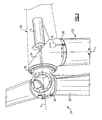
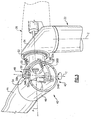
- the hub 42 includes a blade support body 46 rotationally attached through a teeter system 48 to a hollow shaft 50 which permits a teetering motion of the blade support body 46 with respect to the hollow shaft 50.
- the hollow shaft 50 defines a diameter commensurate with a rotor bearing 52, which defines the rotor axis of rotation A relative to the nacelle support structure 34 to provide for an essentially interchangeable rotor 24.
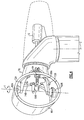
- the hollow shaft 50 may be attached to the rotor bearing 52 via bolts, and is thus "bolt-compatible" and interchangeable with a three ( Figure 2 ) or two ( Figures 3 and 4 ) bladed rotor which will attach to the same rotor bearing 52. That is, the drive-train 33 is located opposite the hollow shaft 50 with respect to the rotor bearing 52 to provide interchangeability.
- This interchangeability is an attractive feature in the wind-energy market, because such interchangeability offers the option of a two-bladed rotor, when cost minimization is the highest priority or a three-bladed rotor for alternative reasons such as aesthetics.
- Interchangeability is also advantageous for the manufacturer of the turbine as a single drive train 33 may be used for multiple bladed rotors to facilitate lower inventory, tooling, and manufacturing costs.
- the rotor rotational velocity at peak aerodynamic efficiency of both the three-bladed and two bladed rotor should be essentially equal. This allows the same gearbox ratio and generator to be used, i.e., the drive train 33 stays the same.
- the solidity must be essentially equal. This solidity is achieved through the large, hollow shaft 50.
- the blades 44 may be fixedly attached to the blade support body 46 without a blade pitch bearing for use with an active yaw system which controls aerodynamic power. The avoidance of blade pitch bearings frees the blade shape from blade-root "necking" restrictions typically associated with pitch capable blades and facilitates the solidity.
- the strength and stiffness of a body is proportional to the body's elastic modulus, times the body's second moment of inertia, about axis A. Since the inertia term increases with the square of the distance between a parcel of material and the centroidal axis, the hollow shaft 50, having most of the mass located far from the axis A, displays higher strength to weight ratios than a conventional solid shaft.
- the blade support body 46 maintains a majority of mass far from the centroidal axis and thus provides higher strength to weight ratios. This lower weight to strength ratio leads to a low-weight rotor.
- the blades 44 are fixedly attached to the blade support body 46, and are characterized by a large root cross-section, that places material as far from the centroidal axis as possible, thereby, increasing the second moment of inertia, and the blade strength and stiffness, as discussed above.
- the teeter system 48 includes a teeter bearing system 54 and teeter restraint system 55 which permits teetering action of the blade support body 46 with respect to the hollow shaft 50.
- At least one teeter restraint 55A, 55B connects the blade support body 46 to the hollow shaft 50 such that the relatively large diameter of the hollow shaft 50 provides widely spaced apart attachment points for the teeter bearing system 54 which lowers teeter-bearing stresses and provides widely spaced apart attachment points for the teeter-restraint system 55 which results in relatively lower stresses on the teeter restraint system 55.
- the relatively large diameter of the hollow shaft 50 also accommodates a relatively large-diameter blade support body - or more generally, a large cross-sectional area when the cross-section of the blade support body is not circular - and blades with a matching large-diameter blade-root section which provides for optimal noise reduction and blade shape.
- the hollow shaft 50 includes shaft arms 58A, 58B which mount to the blade support body 46 through a first teeter bearing 54A and a second teeter bearing 54B.
- the teeter bearings 54A, 54B may be supported upon a reinforced area 59 formed within the blade support body 46.
- the shaft arms 58A, 58B are mounted essentially outside and around the blade support body 46 to provide a pincer arrangement.
- the teeter restraint system 55 must be inside the hub 50 or, at least, on the hub side of the support bearing 52. This placement of the teeter restraint devices facilitates rotor interchangeability.
- the first teeter bearing 54A and the second teeter bearing 54B are aligned along a teetering axis T oriented perpendicular to the axis of rotation A of the blade support body 46, or at a small angle, commonly referred to as "delta.3" by those skilled in the art.
- the first teeter bearing 54A and the second teeter bearing 54B are attached at essentially diametrically opposite locations on the blade support body 46 to permit a teetering motion of the blade support body 46 about the teeter axis T relative to the hollow shaft 50 yet otherwise exclude essentially all other types of relative motion between the blade support body 46 and the hollow shaft 50.
- the teeter restraint system 55 is mounted to the blade support body 46 to extend through an opening 60 defined therethrough to engage with the hollow shaft 50.
- the teeter restraint system 55 includes a first teeter restraint 55A and a second teeter restraint 55B aligned generally perpendicular to the teetering axis T to resist rotation therearound.
- the teeter restraint system 55 limits the teetering motion of the hollow shaft 50.
- the blade support body 46 in this non-limiting embodiment provides a circular cross-section as a compromise between efficient coupling with the hollow shaft 50 which results in a generally equal dimension between separation of the teeter bearings 54A, 54B and the rotor bearing 52 diameter to maximize the blade-root cross-sectional area.
- the circular cross-section facilitates use of a pitch bearing, if desired.
- Both the teeter bearings 54A, 54B and the teeter restraints 55A, 55B produce a moment force on the blade support body 46.
- the hollow shaft 50 having a diameter commensurate with the diameter of the single, relatively large rotor bearing 52, provides for a much larger separation distance between the teeter bearings 54A, 54B and the teeter restraints 55A, 55B from the axis of rotation A. This large spacing reduces the forces, and hence the stresses which provides longer life and lower weight.
- placing the teeter restraint system 55 inside the blade support body 46 provides protection for the teeter restraints 55A, 55B and associated control units (not shown) from harsh weather conditions while facilitating routine maintenance and repair from within the blade support body 46.
- the use of the hollow shaft 50 essentially removes both of these constraints by providing a low-weight hub with a blade-root attachment with large cross-sectional area.
- no pitch bearings are provided which allows the blade root cross-section to grow to dimensions limited only by the transportation restrictions.
- the consequence of the large blade-root cross-section is a blade with higher solidity (i.e. larger chord) with essentially no weight penalty. This is because the increase in the second-moment of inertia provides a material benefit that offsets the increased material needed by the increased blade surface area.
- the net benefit thus, is a two-bladed rotor having essentially the same solidity, hence maximal tip speed and noise emissions, as a three-bladed rotor.
- the noise from a 2-blade rotor will be about the square-root of 2/3 times lower than that of the three-bladed rotor, due to less total trailing-edge length and resultant broad-band noise.
- a blade support body 60 in another non-limiting embodiment defines an elliptical cross-section.
- a set of teeter bearings 62A, 62b are mounted inside the blade support body 60 adjacent the focus points of the elliptical cross-section shape which facilitates a maximal cross-sectional area for both the blade support body 60 and the blade-root cross-section.
- a set of teeter restraints 66A, 66B are pivotally mounted to the blade support body 60 and extend through a respective opening 64 defined thereby to pivotally engage with a hollow shaft 70.
- the first teeter restraint 66A and the second teeter restraint 66B are aligned generally perpendicular to the teetering axis T.
- the hollow shaft 70 includes shaft arms 72A, 72B which penetrate through the blade support body 60 at openings 74A, 74B. Additional material may be required about the openings 74A, 74B to compensate for stress-concentrations. Furthermore, the shaft arms 72A, 72B and the openings 74A, 74B may include complementary shapes. The complementary shapes may be arcuate as illustrated in the disclosed non-limiting embodiment. With an elliptical cross-section, blade pitch bearings are absent and aerodynamic control is achieved through active yaw as readily understood.
- the disclosure provides a two-bladed rotor for wind turbines having a blade support body with a shell-like construction to move all forces and stresses onto the shell and join to the drivetrain via a single large bearing.
- the rotor provides aerodynamic properties for a two-bladed rotor, including tip-speed-ratio at maximum aerodynamic performance, essentially equal to a three-bladed rotor, and integral teeter-restraint devices. These factors provide for cost and weight advantages, as well as for interchangeable, "bolt-compatible" 2 and 3 bladed rotors attachable to a common drive-train.
- the disclosure provides interchangeability with a three-bladed rotor through a common drive-train to allow a manufacturer to offer a lower-cost turbine with two blades when cost is of primary importance to the customer, or with three blades when requirements such as aesthetic reasons are stipulated in the wind-shaft arm development permit. Moreover, the disclosure operates a drive-train for either a two-bladed or three-bladed rotor at optimal aerodynamic efficiency during normal turbine operation.
Landscapes
- Engineering & Computer Science (AREA)
- Life Sciences & Earth Sciences (AREA)
- Sustainable Development (AREA)
- Sustainable Energy (AREA)
- Chemical & Material Sciences (AREA)
- Combustion & Propulsion (AREA)
- Mechanical Engineering (AREA)
- General Engineering & Computer Science (AREA)
- Wind Motors (AREA)
Applications Claiming Priority (1)
| Application Number | Priority Date | Filing Date | Title |
|---|---|---|---|
| US12/558,861 US8562300B2 (en) | 2009-09-14 | 2009-09-14 | Wind turbine with high solidity rotor |
Publications (2)
| Publication Number | Publication Date |
|---|---|
| EP2299108A2 true EP2299108A2 (fr) | 2011-03-23 |
| EP2299108A3 EP2299108A3 (fr) | 2014-12-03 |
Family
ID=43530429
Family Applications (1)
| Application Number | Title | Priority Date | Filing Date |
|---|---|---|---|
| EP10251600.2A Withdrawn EP2299108A3 (fr) | 2009-09-14 | 2010-09-14 | Éolienne dotée d'un rotor hautement résistant |
Country Status (3)
| Country | Link |
|---|---|
| US (1) | US8562300B2 (fr) |
| EP (1) | EP2299108A3 (fr) |
| IL (1) | IL208150A (fr) |
Cited By (1)
| Publication number | Priority date | Publication date | Assignee | Title |
|---|---|---|---|---|
| EP4549727A1 (fr) * | 2023-11-03 | 2025-05-07 | Siemens Gamesa Renewable Energy A/S | Transmission d'éolienne |
Families Citing this family (8)
| Publication number | Priority date | Publication date | Assignee | Title |
|---|---|---|---|---|
| US9797368B2 (en) * | 2008-09-19 | 2017-10-24 | Cortenergy Bv | Wind turbine with low induction tips |
| US8807923B2 (en) * | 2011-02-07 | 2014-08-19 | Vestas Wind Systems A/S | Access apparatus for a wind turbine and method of using same |
| US9041240B2 (en) * | 2011-05-02 | 2015-05-26 | Tadashi Ishimine | Wind turbine apparatus |
| DE102011050777A1 (de) * | 2011-05-31 | 2012-12-06 | Dewind Europe Gmbh | Rotor und Rotorblatt für eine Windkraftanlage |
| US20120025538A1 (en) * | 2011-06-20 | 2012-02-02 | Michael James Luneau | Unitary support frame for use in wind turbines and methods for fabricating same |
| DK2685098T3 (en) * | 2012-07-10 | 2015-05-04 | Siemens Ag | Base frame structure for a wind turbine |
| KR101517759B1 (ko) * | 2014-07-10 | 2015-05-06 | 삼성중공업 주식회사 | 풍력발전기의 요 시스템 조립장치 |
| EP3139033B1 (fr) * | 2015-09-07 | 2019-02-20 | Siemens Aktiengesellschaft | Accès de maintenance pour palier de pale d'éolienne |
Family Cites Families (43)
| Publication number | Priority date | Publication date | Assignee | Title |
|---|---|---|---|---|
| US4083651A (en) | 1976-08-17 | 1978-04-11 | United Technologies Corporation | Wind turbine with automatic pitch and yaw control |
| DE2655026C2 (de) | 1976-12-04 | 1979-01-18 | Ulrich Prof. Dr.-Ing. 7312 Kirchheim Huetter | Windenergiekonverter |
| US4219308A (en) | 1977-11-21 | 1980-08-26 | Ventus Energy Corp. | Torque control system for wind energy conversion devices |
| US4160170A (en) | 1978-06-15 | 1979-07-03 | United Technologies Corporation | Wind turbine generator pitch control system |
| US4189648A (en) | 1978-06-15 | 1980-02-19 | United Technologies Corporation | Wind turbine generator acceleration control |
| US4161658A (en) | 1978-06-15 | 1979-07-17 | United Technologies Corporation | Wind turbine generator having integrator tracking |
| US4342539A (en) | 1979-02-13 | 1982-08-03 | Potter James A | Retractable wind machine |
| US4269563A (en) | 1979-08-09 | 1981-05-26 | Errol W. Sharak | Wind turbine |
| US4352634A (en) | 1980-03-17 | 1982-10-05 | United Technologies Corporation | Wind turbine blade pitch control system |
| US4353681A (en) | 1980-05-19 | 1982-10-12 | United Technologies Corporation | Wind turbine with yaw trimming |
| US4339666A (en) | 1980-12-24 | 1982-07-13 | United Technologies Corporation | Blade pitch angle control for a wind turbine generator |
| US4366386A (en) | 1981-05-11 | 1982-12-28 | Hanson Thomas F | Magnus air turbine system |
| US4632637A (en) | 1981-06-04 | 1986-12-30 | Analytics, Inc. | Wind turbine |
| US4352629A (en) | 1981-10-19 | 1982-10-05 | United Technologies Corporation | Wind turbine |
| US4545728A (en) * | 1983-08-30 | 1985-10-08 | Cheney Jr Marvin C | Wind turbine generator with improved operating subassemblies |
| US4703189A (en) | 1985-11-18 | 1987-10-27 | United Technologies Corporation | Torque control for a variable speed wind turbine |
| US4792700A (en) | 1987-04-14 | 1988-12-20 | Ammons Joe L | Wind driven electrical generating system |
| US5213470A (en) | 1991-08-16 | 1993-05-25 | Robert E. Lundquist | Wind turbine |
| US5295793A (en) | 1992-03-02 | 1994-03-22 | Telect, Inc. | Wind turbine |
| US5354175A (en) * | 1992-03-16 | 1994-10-11 | Northern Power Systems, Inc. | Wind turbine rotor hub and teeter joint |
| US5584655A (en) * | 1994-12-21 | 1996-12-17 | The Wind Turbine Company | Rotor device and control for wind turbine |
| US6327957B1 (en) | 1998-01-09 | 2001-12-11 | Wind Eagle Joint Venture | Wind-driven electric generator apparatus of the downwind type with flexible changeable-pitch blades |
| WO2000009885A1 (fr) | 1998-08-13 | 2000-02-24 | Neg Micon A/S | Procede et dispositif de reglage du pas et d'arret de la rotation des pales d'une eolienne |
| US6441507B1 (en) | 2000-03-22 | 2002-08-27 | The Wind Turbine Company | Rotor pitch control method and apparatus for parking wind turbine |
| US6523781B2 (en) | 2000-08-30 | 2003-02-25 | Gary Dean Ragner | Axial-mode linear wind-turbine |
| US6782667B2 (en) | 2000-12-05 | 2004-08-31 | Z-Tek, Llc | Tilt-up and telescopic support tower for large structures |
| US6465902B1 (en) | 2001-04-18 | 2002-10-15 | The United States Of America As Represented By The Secretary Of The Navy | Controllable camber windmill blades |
| ES2179785B1 (es) | 2001-06-12 | 2006-10-16 | Ivan Lahuerta Antoune | Turbina eolica autotimonante. |
| US7071578B1 (en) | 2002-01-10 | 2006-07-04 | Mitsubishi Heavy Industries, Ltd. | Wind turbine provided with a controller for adjusting active annular plane area and the operating method thereof |
| US6769873B2 (en) | 2002-10-08 | 2004-08-03 | The United States Of America As Represented By The Secretary Of The Navy | Dynamically reconfigurable wind turbine blade assembly |
| US7160083B2 (en) | 2003-02-03 | 2007-01-09 | General Electric Company | Method and apparatus for wind turbine rotor load control |
| US7004724B2 (en) | 2003-02-03 | 2006-02-28 | General Electric Company | Method and apparatus for wind turbine rotor load control based on shaft radial displacement |
| EP1597476A1 (fr) | 2003-02-18 | 2005-11-23 | Forskningscenter Riso | Methode de commande de la charge aerodynamique d'une eolienne en fonction de la mesure de l'ecoulement local au niveau des pales |
| GB0316241D0 (en) | 2003-07-11 | 2003-08-13 | Qinetiq Ltd | Wind speed measurement apparatus and method |
| US7317260B2 (en) | 2004-05-11 | 2008-01-08 | Clipper Windpower Technology, Inc. | Wind flow estimation and tracking using tower dynamics |
| US7344360B2 (en) | 2004-09-29 | 2008-03-18 | General Electric Company | Wind turbine rotor blade with in-plane sweep and devices using same, and methods for making same |
| EP1856408B1 (fr) * | 2005-02-22 | 2017-04-05 | Vestas Wind Systems A/S | Pale d'eolienne |
| ES2370420T3 (es) * | 2005-07-12 | 2011-12-15 | Hamilton Sundstrand Corporation | Turbina eólica con revestimiento de soporte de carga. |
| US7740450B2 (en) * | 2005-11-23 | 2010-06-22 | General Electric Company | Lightweight hub for rotors |
| US7442009B2 (en) | 2006-01-06 | 2008-10-28 | Hamilton Sundstrand Corporation | Driving device for raising or lowering an airfoil |
| US7682126B2 (en) | 2006-06-09 | 2010-03-23 | David Joseph Parker | Tethered propgen |
| US7528497B2 (en) * | 2006-07-11 | 2009-05-05 | Hamilton Sundstrand Corporation | Wind-turbine with load-carrying skin |
| US8246302B2 (en) * | 2007-09-06 | 2012-08-21 | Hamilton Sundstrand Corporation | Teeter-restraint device for wind turbines |
-
2009
- 2009-09-14 US US12/558,861 patent/US8562300B2/en not_active Expired - Fee Related
-
2010
- 2010-09-14 EP EP10251600.2A patent/EP2299108A3/fr not_active Withdrawn
- 2010-09-14 IL IL208150A patent/IL208150A/en not_active IP Right Cessation
Non-Patent Citations (1)
| Title |
|---|
| None |
Cited By (2)
| Publication number | Priority date | Publication date | Assignee | Title |
|---|---|---|---|---|
| EP4549727A1 (fr) * | 2023-11-03 | 2025-05-07 | Siemens Gamesa Renewable Energy A/S | Transmission d'éolienne |
| US12553416B2 (en) | 2023-11-03 | 2026-02-17 | Siemens Gamesa Renewable Energy A/S | Wind turbine drivetrain |
Also Published As
| Publication number | Publication date |
|---|---|
| IL208150A0 (en) | 2011-01-31 |
| US8562300B2 (en) | 2013-10-22 |
| EP2299108A3 (fr) | 2014-12-03 |
| IL208150A (en) | 2015-06-30 |
| US20110064578A1 (en) | 2011-03-17 |
Similar Documents
| Publication | Publication Date | Title |
|---|---|---|
| US8562300B2 (en) | Wind turbine with high solidity rotor | |
| EP2304227B1 (fr) | Éolienne à pales portées du côté sous le vent | |
| EP2194267B1 (fr) | Manche pour le pied d'une pale d'éolienne | |
| EP1861619B1 (fr) | Roue de tension dans un systeme de rotor pour turbines hydrauliques et eoliennes | |
| EP1890034B1 (fr) | Moulin à vent à axe horizontal | |
| KR101411057B1 (ko) | 풍력 터빈 로터 | |
| DK178423B1 (en) | Rotor Blade Assembly | |
| EP2341245B1 (fr) | Appareil pour augmenter la portance d'une pale d'éolienne | |
| US20090148291A1 (en) | Multi-section wind turbine rotor blades and wind turbines incorporating same | |
| EP2075464A2 (fr) | Partie supérieure d'une tour inclinée en avant | |
| US20090297355A1 (en) | Wind turbine blade planforms with twisted and tapered tips | |
| WO2011134985A1 (fr) | Pale d'éolienne pourvue d'un ensemble bec | |
| WO2010133649A2 (fr) | Turbine éolienne et pale de turbine éolienne | |
| US8408877B2 (en) | Wind turbine blades with twisted tips | |
| AU2008235238A1 (en) | Wind wheel | |
| WO2010056599A1 (fr) | Pale d'éolienne à axe vertical | |
| WO2010048958A2 (fr) | Aérogénérateur comprenant un rotor à pales inclinées vers l'arrière | |
| EP4684124A1 (fr) | Éolienne à pas variable | |
| US20180017037A1 (en) | Hub and Rotor Assemby for Wind Turbines with Conjoined Turbine Blades |
Legal Events
| Date | Code | Title | Description |
|---|---|---|---|
| PUAI | Public reference made under article 153(3) epc to a published international application that has entered the european phase |
Free format text: ORIGINAL CODE: 0009012 |
|
| AK | Designated contracting states |
Kind code of ref document: A2 Designated state(s): AL AT BE BG CH CY CZ DE DK EE ES FI FR GB GR HR HU IE IS IT LI LT LU LV MC MK MT NL NO PL PT RO SE SI SK SM TR |
|
| AX | Request for extension of the european patent |
Extension state: BA ME RS |
|
| RIN1 | Information on inventor provided before grant (corrected) |
Inventor name: BERTOLOTTI, FABIO P. |
|
| PUAL | Search report despatched |
Free format text: ORIGINAL CODE: 0009013 |
|
| AK | Designated contracting states |
Kind code of ref document: A3 Designated state(s): AL AT BE BG CH CY CZ DE DK EE ES FI FR GB GR HR HU IE IS IT LI LT LU LV MC MK MT NL NO PL PT RO SE SI SK SM TR |
|
| AX | Request for extension of the european patent |
Extension state: BA ME RS |
|
| RIC1 | Information provided on ipc code assigned before grant |
Ipc: F03D 11/00 20060101ALI20141028BHEP Ipc: F03D 1/00 20060101AFI20141028BHEP |
|
| 17P | Request for examination filed |
Effective date: 20150513 |
|
| RBV | Designated contracting states (corrected) |
Designated state(s): AL AT BE BG CH CY CZ DE DK EE ES FI FR GB GR HR HU IE IS IT LI LT LU LV MC MK MT NL NO PL PT RO SE SI SK SM TR |
|
| STAA | Information on the status of an ep patent application or granted ep patent |
Free format text: STATUS: THE APPLICATION HAS BEEN WITHDRAWN |
|
| 18W | Application withdrawn |
Effective date: 20160309 |