EP2299111A2 - Procédé et système de vérification de fonctionnement d'une éolienne - Google Patents
Procédé et système de vérification de fonctionnement d'une éolienne Download PDFInfo
- Publication number
- EP2299111A2 EP2299111A2 EP10173657A EP10173657A EP2299111A2 EP 2299111 A2 EP2299111 A2 EP 2299111A2 EP 10173657 A EP10173657 A EP 10173657A EP 10173657 A EP10173657 A EP 10173657A EP 2299111 A2 EP2299111 A2 EP 2299111A2
- Authority
- EP
- European Patent Office
- Prior art keywords
- wind turbine
- verification
- controller
- verification device
- user
- Prior art date
- Legal status (The legal status is an assumption and is not a legal conclusion. Google has not performed a legal analysis and makes no representation as to the accuracy of the status listed.)
- Granted
Links
- 238000000034 method Methods 0.000 title description 38
- 238000012795 verification Methods 0.000 claims abstract description 107
- 230000007246 mechanism Effects 0.000 claims abstract description 19
- 238000012360 testing method Methods 0.000 description 62
- 238000004891 communication Methods 0.000 description 10
- 238000010586 diagram Methods 0.000 description 8
- 230000009471 action Effects 0.000 description 3
- 230000008878 coupling Effects 0.000 description 3
- 238000010168 coupling process Methods 0.000 description 3
- 238000005859 coupling reaction Methods 0.000 description 3
- 230000004044 response Effects 0.000 description 3
- 238000013518 transcription Methods 0.000 description 3
- 230000035897 transcription Effects 0.000 description 3
- 230000006870 function Effects 0.000 description 2
- 230000006698 induction Effects 0.000 description 2
- 239000007787 solid Substances 0.000 description 2
- 230000033228 biological regulation Effects 0.000 description 1
- 239000003990 capacitor Substances 0.000 description 1
- 230000001413 cellular effect Effects 0.000 description 1
- 230000000875 corresponding effect Effects 0.000 description 1
- 238000001514 detection method Methods 0.000 description 1
- 230000000694 effects Effects 0.000 description 1
- 230000005611 electricity Effects 0.000 description 1
- 238000004146 energy storage Methods 0.000 description 1
- 239000000835 fiber Substances 0.000 description 1
- 230000001939 inductive effect Effects 0.000 description 1
- 239000004973 liquid crystal related substance Substances 0.000 description 1
- 238000007726 management method Methods 0.000 description 1
- 238000012986 modification Methods 0.000 description 1
- 230000004048 modification Effects 0.000 description 1
- 238000005457 optimization Methods 0.000 description 1
- 230000008569 process Effects 0.000 description 1
- 230000003252 repetitive effect Effects 0.000 description 1
- 238000012549 training Methods 0.000 description 1
- 238000012546 transfer Methods 0.000 description 1
- 230000001131 transforming effect Effects 0.000 description 1
- 238000013024 troubleshooting Methods 0.000 description 1
- 238000011179 visual inspection Methods 0.000 description 1
Images



Classifications
-
- F—MECHANICAL ENGINEERING; LIGHTING; HEATING; WEAPONS; BLASTING
- F03—MACHINES OR ENGINES FOR LIQUIDS; WIND, SPRING, OR WEIGHT MOTORS; PRODUCING MECHANICAL POWER OR A REACTIVE PROPULSIVE THRUST, NOT OTHERWISE PROVIDED FOR
- F03D—WIND MOTORS
- F03D7/00—Controlling wind motors
- F03D7/02—Controlling wind motors the wind motors having rotation axis substantially parallel to the air flow entering the rotor
- F03D7/04—Automatic control; Regulation
- F03D7/042—Automatic control; Regulation by means of an electrical or electronic controller
- F03D7/047—Automatic control; Regulation by means of an electrical or electronic controller characterised by the controller architecture, e.g. multiple processors or data communications
-
- F—MECHANICAL ENGINEERING; LIGHTING; HEATING; WEAPONS; BLASTING
- F03—MACHINES OR ENGINES FOR LIQUIDS; WIND, SPRING, OR WEIGHT MOTORS; PRODUCING MECHANICAL POWER OR A REACTIVE PROPULSIVE THRUST, NOT OTHERWISE PROVIDED FOR
- F03D—WIND MOTORS
- F03D17/00—Monitoring or testing of wind motors, e.g. diagnostics
-
- Y—GENERAL TAGGING OF NEW TECHNOLOGICAL DEVELOPMENTS; GENERAL TAGGING OF CROSS-SECTIONAL TECHNOLOGIES SPANNING OVER SEVERAL SECTIONS OF THE IPC; TECHNICAL SUBJECTS COVERED BY FORMER USPC CROSS-REFERENCE ART COLLECTIONS [XRACs] AND DIGESTS
- Y02—TECHNOLOGIES OR APPLICATIONS FOR MITIGATION OR ADAPTATION AGAINST CLIMATE CHANGE
- Y02E—REDUCTION OF GREENHOUSE GAS [GHG] EMISSIONS, RELATED TO ENERGY GENERATION, TRANSMISSION OR DISTRIBUTION
- Y02E10/00—Energy generation through renewable energy sources
- Y02E10/70—Wind energy
- Y02E10/72—Wind turbines with rotation axis in wind direction
Definitions
- the present application relates generally to wind turbines and, more particularly, to a method and system for verifying wind turbine operation.
- wind turbines are complicated machines that may include a large number of mechanical and electrical components.
- a wind turbine When a wind turbine is assembled at a site, typically one or more tests are performed to verify proper wind turbine operation. More specifically, often a wind turbine is tested at various stages of assembly before being delivered to a customer. For example, a wind turbine may undergo a pre-commissioning acceptance test (PCAT), a field commissioning acceptance test (FCAT), and a customer commissioning test (CCT). Only after these tests have been completed may the wind turbine be delivered to the customer.
- PCAT pre-commissioning acceptance test
- FCAT field commissioning acceptance test
- CCT customer commissioning test
- the commissioning tests, PCAT, FCAT, and CCT may be performed by a wind turbine commissioning technician (also known as a commissioner).
- the commissioner performs at least one of a PCAT, FCAT, and CCT using a paper copy of commissioning verification procedures.
- the paper copies of such verification procedures may be large and cumbersome.
- many of the tests are performed within a nacelle of a wind turbine, where space may be limited.
- Commissioners may also need to bring other equipment into the wind turbine and/or nacelle. As such, commissioners may not have sufficient room for the voluminous paper copies.
- commissioners must undergo a lengthy training process regarding proper wind turbine verification procedures. Moreover, commissioners may make mistakes in following the wind turbine verification procedures from the paper copy. For example, often the results of the tests are recorded on a paper copy, and transcription errors may occur when such recorded results are transferred into a centralized database or other data repository. Moreover, such transcriptions may be costly and/or time-consuming.
- a wind turbine verification system in one embodiment, includes a wind turbine controller having a plurality of wind turbine operating parameters stored therein, and a verification device that includes a processor, a memory device, and a user input mechanism.
- the verification device is configured to communicatively couple to the wind turbine controller via a data link.
- the verification device is also configured to receive at least one parameter from the wind turbine controller and execute a verification program on the wind turbine controller, wherein the verification program is configured to iterate through a plurality of predefined tasks.
- the verification device is configured to verify at least one operating condition of a wind turbine based on the executed verification program.
- a method for verifying proper operation of a wind turbine includes providing a wind turbine controller having a plurality of wind turbine operating parameters stored therein, and a verification device having a processor, a memory device, and a user input mechanism.
- the method includes coupling the wind turbine controller in communication with the verification device via a data link and receiving at least one of the wind turbine operating parameters from the wind turbine controller.
- the method also includes executing a verification program on the wind turbine controller, wherein the verification program is configured to iterate through a plurality of predefined tasks, and verifying at least one operating condition of the wind turbine based on the executed verification program.
- a verification device for use in verifying wind turbine operation.
- the device includes a processor, a memory device, and a user input mechanism.
- the device is configured to communicatively couple, via a data link, to a wind turbine controller having a plurality of wind turbine operating parameters stored therein.
- the device is also configured to receive at least one parameter from the wind turbine controller and execute a verification program on the wind turbine controller, wherein the verification program is configured to iterate through a plurality of predefined tasks.
- the verification device is configured to verify at least one operating condition of a wind turbine based on the executed verification program.
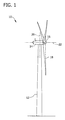
- FIG. 1 illustrates an exemplary wind turbine 10.
- wind turbine 10 includes a tower 12, a nacelle 14 that is coupled to tower 12, a hub 16 that is coupled to nacelle 14, and at least one blade 18 that is coupled to hub 16.
- Tower 12 provides support for nacelle 14, hub 16, and blade 18.
- Nacelle 14 is coupled to tower 12.
- Nacelle 14 houses components (not shown) for use in transforming rotational energy of blade 18 into electricity.
- Nacelle 14 may be constructed as is known in the art.
- Hub 16 is coupled to nacelle 14.
- Hub 16 provides a rotatable housing for at least one blade 18.
- At least one blade 18 is coupled to hub 16. In the exemplary embodiment, three blades 18 are coupled to hub 16.
- Blades 18 are rotatable about an axis of rotation 22 when wind strikes blades 18.
- each blade 18 is oriented substantially perpendicularly to the ground.
- Each blade 18 rotates through substantially the same plane of rotation and substantially parallel to a centerline axis 20 of tower 12.
- Figure 2 illustrates a block diagram of an exemplary wind turbine control system 70 that may be used with wind turbine 10 (shown in Figure 1 ).
- Control system 70 is coupled to components within hub 16, blades 18, nacelle 14, and tower 12.
- hub 16 includes a pitch controller 40, at least one pitch drive 42, a hub backup power supply 44, and a hub sensor 48.
- Pitch controller 40 is coupled to blades 18 through pitch drives 42.
- hub 16 includes three pitch drives 42, wherein pitch controller 40 is coupled to each blade 18 via a respective pitch drive 42.
- pitch controller 40 is located within hub 16 and controls, for example, a pitch angle (not shown) and/or a relative position (not shown) of blades 18. Moreover, pitch controller 40 communicates with a wind turbine controller 60 via a communication network 50.
- pitch controller 40 includes a programmable logic controller (PLC).
- PLC programmable logic controller
- pitch controller 40 includes a microprocessor, a microcontroller, a field programmable gate array (FPGA) or any other programmable circuit that enables pitch controller 40 to operate as described herein.
- controls includes, but is not limited to only including, issuing commands to be implemented by exercising oversight and supervision of, and/or directing operation of, one or more subject components.
- control also includes a regulation-type of control, e.g., a feedback-loop regulation.
- pitch drives 42 receive one or more pitch commands from pitch controller 40, and in response, rotate blades 18 to a desired position and/or pitch angle identified by the pitch commands.
- Pitch drives 42 may rotate blades 18 using, for example, hydraulic, electric, and/or gear-driven means.
- hub sensor 48 determines a speed of rotation of and/or a load induced to hub 16.
- Hub backup power supply 44 may include, for example, a battery, a magnetic energy storage device, and/or one or more capacitors. Hub backup power supply 44 provides electrical power to components within hub 16, such as pitch controller 40, pitch drives 42, and hub sensor 48.
- each blade 18 includes a blade sensor 46 coupled thereto.
- Each blade sensor 46 is also coupled to pitch controller 40.
- Blade sensors 46 enable a speed of rotation of and/or a load induced to each blade 18 to be determined.
- nacelle 14 includes a gearbox 52, a brake 54, a generator 56, a battery 58, and a nacelle controller 62. In an alternative embodiment, nacelle 14 does not include gearbox 52. In another alternative embodiment, nacelle 14 does not include nacelle controller 62. In the exemplary embodiment, gearbox 52 augments the rotation of a main rotor shaft (not shown) driven by the rotation of blades 18, thereby inducing a higher amount of rotational energy to generator 56. Brake 54 may provide emergency stopping power to generator 56 and/or to wind turbine 10 operation in an event of a fault or other error condition. Generator 56 transforms the rotational energy of the main rotor shaft into electrical energy.
- Generator 56 may be of any suitable type that enables wind turbine 10 to function as described herein.
- generator 56 is a wound rotor induction generator, such as a doubly fed induction generator.
- Battery 58 provides backup electrical power to nacelle 14 and tower 12 components.
- Nacelle controller 62 controls the operation of components within nacelle 14, such as gearbox 52, brake 54, generator 56, and/or battery 58.
- nacelle controller 62 is coupled to pitch controller 40 and to wind turbine controller 60 via communication network 50. More specifically, in the exemplary embodiment, nacelle controller 62 is coupled to pitch controller 40 via a nacelle-hub network 66, and to wind turbine controller 60 via a nacelle-tower network 68.
- wind turbine controller 60 is located within tower 12. In an alternative embodiment, wind turbine controller 60 is located within nacelle 14. Moreover, in the exemplary embodiment, wind turbine controller 60 operates as a master controller of wind turbine 10 and of pitch control system 70, and may include a computer or other processor that is programmed to execute control algorithms.
- processor includes, without limitation, any programmable system including systems and microcontrollers, reduced instruction set circuits (RISC), application specific integrated circuits (ASIC), programmable logic circuits (PLC), and any other circuit capable of executing the functions described herein.
- Wind turbine controller 60 may control other controllers of wind turbine 10, such as pitch controller 40, communicate with other wind turbines (not shown) and/or a wind farm management system (not shown), and/or perform error handling and operational optimization. Moreover, wind turbine controller 60 may also execute a SCADA (Supervisory, Control and Data Acquisition) program.
- SCADA Supervisory, Control and Data Acquisition
- Hub 16 is coupled to nacelle 14 and to tower 12 via communication network 50.
- Communication network 50 includes nacelle-hub network 66 and nacelle-tower network 68. More specifically, in the exemplary embodiment, hub 16 is coupled to nacelle 14 via nacelle-hub network 66, and nacelle 14 is coupled to tower 12 via nacelle-tower network 68.
- pitch controller 40 is coupled to wind turbine controller 60 via nacelle-hub network 66 and via nacelle-tower network 68.
- nacelle-hub network 66 uses a slip ring connection to transmit signals via a serial communication protocol or another communication protocol, such as broadband over power line (BPL).
- BPL broadband over power line
- nacelle-hub network 66 includes any other connection that enables network 66 to operate as described herein.
- nacelle-tower network 68 includes one or more of such connections as Ethernet LAN, wireless LAN, a Controller Area Network (CAN) bus, fiber optic connection, or any other communication connection (all not shown) that enables nacelle-tower network 68 to operate as described herein.
- CAN Controller Area Network
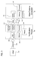
- FIG 3 illustrates a block diagram of an exemplary wind turbine verification device 100 that may be used with wind turbine control system 70 (shown in Figure 2 ).
- verification device 100 includes a processor 102 that is coupled to a display 104, a memory 106, and a user interface 108.
- Verification device 100 also includes a controller interface 112 that is communicatively coupled to wind turbine controller 60 (shown in Figure 2 ) via a data link 114. Verification device 100 includes a verification program 110 that receives input from user interface 108 and from controller interface 112 via device processor 102, and that provides output to controller interface 112 and display 104 via device processor 102.
- Verification device 100 includes any device that is capable of accessing wind turbine controller 60 and interacting with a user 126 as described herein.
- verification device 100 may include, without limitation, a laptop computer, a cellular phone, a smart phone, and/or a personal digital assistant (PDA).
- PDA personal digital assistant
- verification device 100 includes a laptop computer.
- Device processor 102 is coupled to device display 104, to memory 106, and to user interface 108.
- Device processor 102 is also coupled to controller interface 112 and to data link 114.
- device processor 102 is a microprocessor.
- device processor 102 is a programmable logic controller (PLC), a microcontroller, a field programmable gate array (FPGA), and/or any other programmable circuit that enables verification device 100 to operate as described herein.
- PLC programmable logic controller
- FPGA field programmable gate array
- device display 104 is a liquid crystal display (LCD).
- device display 104 is a cathode ray tube (CRT), a plasma display, or any other type of display that is capable of displaying graphical representations of data and text to a user.
- Memory 106 may include, without limitation, a hard disk drive, a solid state drive, a diskette, a flash drive, a compact disc, a digital video disc, and/or random access memory (RAM).
- User interface 108 may include, without limitation, a keyboard, a keypad, a pointing device, a touch sensitive screen, and/or an audio input device.
- Data link 114 may include, without limitation, an Ethernet cable, a wireless Ethernet connection, a universal serial bus (USB) cable, a serial cable, and/or a parallel cable.
- a user 126 interacts with verification device 100 by viewing information displayed on device display 104 and manipulating user interface 108 to input at least one user command 128.
- Verification program 110 includes at least one software module that communicates with wind turbine controller 60 via device processor 102.
- verification program 110 also includes at least one predefined list of specification data for at least one wind turbine component.
- the list of specification data may include, without limitation, a maximum rated speed of wind turbine 10, a serial number of wind turbine 10 and/or wind turbine controller 60, and/or a maximum power output of generator 56 (shown in Figure 2 ).
- wind turbine controller 60 includes a verification device interface 116 that is communicatively coupled to verification device 100 via data link 114. Controller 60 also includes a processor 118 and a memory 120 that includes a plurality of wind turbine operating parameters 122. In an alternative embodiment, a plurality of wind turbine operating parameters 122 are stored within a wind turbine component, such as, without limitation, nacelle controller 62 and/or pitch controller 40 (shown in Figure 2 ). Controller processor 118 is coupled to verification device interface 116 and to controller memory 120. In the exemplary embodiment, controller processor 118 is a programmable logic controller (PLC).
- PLC programmable logic controller
- controller processor 118 is a microprocessor, a microcontroller, a field programmable gate array (FPGA) or any other programmable circuit that enables wind turbine controller 60 to operate as described herein.
- Controller memory 120 may include, without limitation, a hard disk drive, a solid state drive (SSD), a diskette, a flash drive, a compact disc (CD), a digital video disc (DVD), and/or random access memory (RAM).
- processor 102 During operation, user 126 inputs a user command 128 into verification device 100 via user interface 108.
- Processor 102 communicates each user command 128 input to the verification program 110 executing on device 100.
- Device processor 102 utilizes verification program 110 to analyze user command 128 and in response, transmits data 124 representing a device command 130 to wind turbine controller 60 via data link 114 and via device interface 116.
- processor 102 upon input of a user command 128, transmits data 124 representing a plurality of device commands 130 to wind turbine controller 60 via device interface 116.
- controller processor 118 Upon receipt of a device command 130, controller processor 118 analyzes device command 130 and executes at least one corresponding action.
- Such an action may include returning data 124 representing one or more wind turbine operating parameters 122 to verification program 110, modifying a parameter 122, and/or modifying an operation of one or more wind turbine components (not shown).
- controller processor 118 may transmit the device command 130 to another controller within control system 70, such as, nacelle controller 62 or pitch controller 40 (shown in Figure 2 ).
- controller processor 118 may also transmit data 124, representing a status of wind turbine 10 and/or a wind turbine component, to verification program 110.
- controller processor 118 may report a result of device command 130, such as whether device command 130 was implemented successfully, and/or a failure message if the implementation of device command 130 is unsuccessful.
- Verification device 100 may be programmed to receive updates to software installed on device 100, such as verification program 110, via an internet connection, via a CD or DVD, via a flash drive (all not shown), and/or via any other suitable software update medium.
- updates may include, without limitation, an update for verification program 110 as a whole, for one or more software modules or other components of verification program 110, and/or for the list of wind turbine component specification data.
- Figure 4 illustrates a flow diagram of an exemplary method 200 for verifying wind turbine operation that may be used with verification device 100 (shown in Figure 3 ).
- Figure 5 illustrates a flow diagram of an exemplary predefined test 224 that may be used with method 200 (shown in Figure 4 ).
- a user 126 shown in Figure 3
- connects 202 verification device 100 to wind turbine controller 60 via data link 114 shown in Figure 3 .
- verification device 100 and wind turbine controller 60 may engage in a mutual "handshaking" and/or configuration procedure to establish a configuration of a data transfer protocol.
- Verification program 110 (shown in Figure 3 ) is executed and predefined test 224 is started 204.
- verification program 110 includes one predefined test 224, such as, without limitation, a PCAT, an FCAT, or a CCT.
- verification program 110 includes a plurality of predefined tests 224, such as, but not limited to, a PCAT, an FCAT, and/or a CCT, and user 126 selects the desired test 224 to start 204 via user interface 108 (shown in Figure 3 ).
- Test 224 includes at least one predefined test stage 226, and each test stage 226 includes at least one predefined task 228.
- test 224 iterates 206 through each test stage 226, and performs 208 the tasks 228 included in each stage 226.
- tasks 228 may include, without limitation, instructing 230 user 126 to perform an identified subtask, accepting 232 input from user 126, transmitting 234 one or more commands to wind turbine controller 60, retrieving or selecting 236 data from a list, displaying 238 data to user 126 via display 104 (shown in Figure 3 ), storing 240 data in device memory 106, associating 242 data, and/or any other task 228 defined in test 224.
- User 126 may be instructed 230, without limitation, to manually adjust a wind turbine component or to visually inspect a component. Moreover, user 126 may be instructed 230 to refer to documentation or to obtain troubleshooting information to complete a task 228 and/or test stage 226.
- User 126 may input data into test 224 (i.e., the test 224 may accept 232 input from user 126) in response to a prompt from test 224.
- user 126 may input data relating to one or more manual adjustments and/or visual inspections of a wind turbine component, or may input data indicating completion of, or failure to complete, a task 228 or subtask.
- data may include, without limitation, notes or comments from user 126, or user commands 128 (shown in Figure 3 ).
- User 126 may also enter their name and/or company information. Alternatively, user 126 may input any other data required by test 224.
- test 224 transmits 234 one or more commands to controller 60.
- commands may include user commands 128 and/or predefined commands stored in device memory 106 (shown in Figure 3 ).
- input of one user command 128 may result in test 224 transmitting 234 a plurality of commands to controller 60.
- a predefined command stored in device memory 106 may cause test 224 to transmit 234 a plurality of commands to controller 60.
- the commands that test 224 transmits 234 to controller 60 may include, without limitation, requests for data 124 (shown in Figure 2 ) from controller 60 and/or other controllers in control system 70 (shown in Figure 2 ).
- Such commands may also include, without limitation, commands to write data 124 to controller 60, to another controller in control system 70, and/or to other wind turbine components.
- Wind turbine controller 60 may transmit a result of each command sent to wind turbine controller 60, such as whether each command was implemented successfully, and/or may transmit a failure message if the implementation of each command is unsuccessful.
- test 224 indicates a failure and may exit or stop execution.
- Test 224 may indicate a failure by, without limitation, displaying an error message to user 126, generating an audible alert, and/or exiting.
- test 224 Upon detection of a failure, test 224 also may generate a failure report or log, and may store a record of the failure in device memory 106.
- the failure record may include, without limitation, the failure report or log, a list of commands transmitted 234 to wind turbine controller 60, a list and/or status of one or more wind turbine operating parameters 122, and/or a record of the test 224, test stage 226, and/or task 228 that was in progress when the failure was detected.
- Test 224 may select 236 data from a list, table, or other data structure stored in device memory 106 or controller memory 120 (shown in Figure 3 ) to facilitate performing 208 a task 228.
- test 224 may select 236 data, such as an optimal idle position for blades 18 (shown in Figure 2 ), from the predefined list or table of wind turbine component specification data stored in device memory 106.
- test 224 may associate data from the list or table with one or more wind turbine operating parameters 122 received from wind turbine controller 60.
- test 224 may receive a serial number of wind turbine controller 60 and may, based on that serial number, retrieve a maximum rated speed of wind turbine 10 from the list or table stored in device memory 106 or controller memory 120.
- test 224 displays 238 data using device display 104 (shown in Figure 3 ).
- test 224 may display 238 a graph of a speed of rotation of blades 18, a pitch speed of blades 18, and/or an output voltage and/or current transmitted from generator 56 (shown in Figure 2 ).
- test 224 may display 238 text and/or graphical data to user 126 representing status information and/or one or more results of test 224, test stages 226, and/or tasks 228.
- test data is stored 240 in device memory 106 for later retrieval.
- Such test data may include, without limitation, a list of commands transmitted 234 to wind turbine controller 60, a record of test 224, test stages 226, and/or tasks 228 executed, and/or a record of any failures that occurred.
- data may be associated 242 with a test 224, one or more test stages 226, and/or one or more tasks 228. For example, and without limitation, if user 126 enters data representing one or more notes or comments during a particular task 228, test 224 may associate 242 the one or more notes or comments with that task 228.
- Test 224 may associate 242 such data by, for example, creating a programmatic link between task 228 and the data, or by creating a relation between task 228 and the data in a database. As such, if test 224, test stage 226, and/or task 228 is retrieved later, the associated 242 data will be automatically retrieved as well.
- Test 224 is completed 210 after iterating 206 through all test stages 226.
- verification program 110 stores 212 a record of test 224, including any associated 242 test data, in device memory 106.
- the record of test 224 may be uploaded 214 to a central repository, such as a server. As such, costly and/or time consuming transcription of the record of test 224 may be facilitated to be reduced or eliminated.
- Various technical effects of the verification system and method described herein may include at least one of (a) providing a wind turbine controller including a plurality of wind turbine operating parameters, and a verification device including a processor, a memory device, and a user input mechanism; (b) coupling a wind turbine controller in communication with a verification device via a data link; (c) receiving at least one wind turbine operating parameter from a wind turbine controller; (d) executing a verification program on a wind turbine controller, wherein the verification program iterates through a plurality of predefined tasks; and (e) verifying at least one operating condition of a wind turbine based on an executed verification program.
- the above-described embodiments facilitate providing an efficient and cost-effective method and device for verifying proper wind turbine operation.
- the verification device facilitates reducing an amount of documentation and other equipment that a technician may be required to use to verify wind turbine operation.
- the verification device facilitates updating test stages, tasks, and/or procedures and promotes maintaining a substantially uniform testing of wind turbines.
- the verification device facilitates automating repetitive and/or tedious tasks, such as looking up component specifications and transmitting them to a wind turbine controller.
- the verification device facilitates uploading test results and technician notes to a centralized database or other repository.
- Exemplary embodiments of a method, system, and device for verifying wind turbine operation are described above in detail.
- the method, system, and device are not limited to the specific embodiments described herein, but rather, components of the system and device and/or steps of the method may be utilized independently and separately from other components and/or steps described herein.
- the verification device may also be used in combination with other verification systems and methods, and is not limited to practice with only the wind turbine system as described herein. Rather, the exemplary embodiment can be implemented and utilized in connection with many other power system applications.
- the exemplary embodiment may be used to verify operation of generators separate from wind turbine generators.
- the exemplary embodiment may be used to verify operation of one or more solar power system generators.
- the exemplary embodiment may be used to verify operation of one or more generators in other renewable energy power systems, or in any other power system.
Landscapes
- Engineering & Computer Science (AREA)
- Life Sciences & Earth Sciences (AREA)
- Sustainable Development (AREA)
- Sustainable Energy (AREA)
- Chemical & Material Sciences (AREA)
- Combustion & Propulsion (AREA)
- Mechanical Engineering (AREA)
- General Engineering & Computer Science (AREA)
- Wind Motors (AREA)
Applications Claiming Priority (1)
| Application Number | Priority Date | Filing Date | Title |
|---|---|---|---|
| US12/553,434 US7948103B2 (en) | 2009-09-03 | 2009-09-03 | Method and system for verifying wind turbine operation |
Publications (3)
| Publication Number | Publication Date |
|---|---|
| EP2299111A2 true EP2299111A2 (fr) | 2011-03-23 |
| EP2299111A3 EP2299111A3 (fr) | 2017-09-06 |
| EP2299111B1 EP2299111B1 (fr) | 2020-03-18 |
Family
ID=42222085
Family Applications (1)
| Application Number | Title | Priority Date | Filing Date |
|---|---|---|---|
| EP10173657.7A Active EP2299111B1 (fr) | 2009-09-03 | 2010-08-23 | Système de vérification de fonctionnement d'une éolienne |
Country Status (3)
| Country | Link |
|---|---|
| US (1) | US7948103B2 (fr) |
| EP (1) | EP2299111B1 (fr) |
| CN (1) | CN102011701B (fr) |
Families Citing this family (18)
| Publication number | Priority date | Publication date | Assignee | Title |
|---|---|---|---|---|
| DE102009037237A1 (de) * | 2009-08-12 | 2011-02-17 | Repower Systems Ag | Verfahren und Anordnung zur automatischen Konfigurationsparameterkontrolle bei Windenergieanlagen |
| US8162788B2 (en) * | 2009-08-27 | 2012-04-24 | General Electric Company | System, device and method for wind turbine control based on operating profiles |
| US7880320B2 (en) * | 2009-10-30 | 2011-02-01 | General Electric Company | System, device, and method for controlling a wind turbine using seasonal parameters |
| CN102803715B (zh) * | 2010-02-12 | 2015-03-25 | 三菱重工业株式会社 | 用于风力涡轮发电机的手持终端、风力涡轮发电机和风力站 |
| GB201109897D0 (en) * | 2011-06-13 | 2011-07-27 | Romax Technology Ltd | A method for managing wind farms |
| US8803387B2 (en) * | 2012-02-21 | 2014-08-12 | Regal Beloit America, Inc. | Interface module and method for communicating with an electric machine |
| CA2899364C (fr) | 2013-01-26 | 2019-09-24 | Equipements Wind Will Inc. | Systeme d'eolienne |
| US20150381443A1 (en) * | 2013-02-15 | 2015-12-31 | Aktiebolaget Skf | Condition monitoring system and method for creating or updating service information |
| ITRM20130272A1 (it) * | 2013-05-08 | 2014-11-09 | Consiglio Nazionale Ricerche | Metodo e relativo sistema per la conversione di energia meccanica, proveniente da un generatore comandato da una turbina, in energia elettrica. |
| IN2013CH06141A (fr) * | 2013-12-30 | 2015-07-03 | Gen Electric | |
| US10428796B2 (en) * | 2015-03-27 | 2019-10-01 | The Aes Corporation | Systems and methods for optimizing the power generated by wind turbines |
| DE102015120306A1 (de) * | 2015-11-24 | 2017-05-24 | Wobben Properties Gmbh | Verfahren zum Ausgeben von Steuerbefehlen oder Ereignismeldungen für eine Windenergieanlage oder einen Windpark sowie eine Auswerteeinrichtung und ein System hierfür |
| CN107701367A (zh) * | 2016-08-08 | 2018-02-16 | 锐电科技有限公司 | 一种提高分布式风电机组发电量的装置及方法 |
| JP6503419B2 (ja) | 2017-07-07 | 2019-04-17 | 三菱重工業株式会社 | 風力発電施設のデータ収集システム及びデータ収集方法並びに風力発電施設 |
| CN111670302B (zh) | 2017-12-06 | 2023-10-20 | 维斯塔斯风力系统集团公司 | 风力涡轮机控制器的配置 |
| CN110824991B (zh) * | 2019-11-14 | 2020-12-08 | 武汉伊科设备制造有限公司 | 风车远程自动控制系统及控制方法 |
| EP4358347A1 (fr) * | 2022-10-19 | 2024-04-24 | Wobben Properties GmbH | Procédé de mesure d'une éolienne sélectionnée comme une installation d'essai |
| CN117492405B (zh) * | 2024-01-02 | 2024-03-08 | 东方电气风电股份有限公司 | 一种基于现场总线的风电机组控制系统校验方法 |
Family Cites Families (38)
| Publication number | Priority date | Publication date | Assignee | Title |
|---|---|---|---|---|
| US5416416A (en) | 1992-02-24 | 1995-05-16 | Bisher; Roger C. | Method and apparatus for testing an auxiliary power system |
| US20020029097A1 (en) | 2000-04-07 | 2002-03-07 | Pionzio Dino J. | Wind farm control system |
| US6833636B1 (en) | 2001-06-04 | 2004-12-21 | Chromalox, Inc. | Compact load bank for testing power systems |
| US7099800B2 (en) | 2001-09-28 | 2006-08-29 | Neg Micon Control Systems A/S | Method and a computer for handling operational data of wind power plants |
| US20030097315A1 (en) * | 2001-11-16 | 2003-05-22 | Siemens Westinghouse Power Corporation | System and method for identifying a defective component in a network environment |
| US6739512B2 (en) * | 2001-11-16 | 2004-05-25 | Siemens Westinghouse Power Corporation | System and method for tracking a component in a network environment |
| DE10323785B4 (de) * | 2003-05-23 | 2009-09-10 | Wobben, Aloys, Dipl.-Ing. | Verfahren zum Erkennen eines Eisansatzes an Rotorblättern |
| US7118338B2 (en) * | 2004-06-30 | 2006-10-10 | General Electric Company | Methods and apparatus for twist bend coupled (TCB) wind turbine blades |
| DE102004056223B4 (de) | 2004-11-17 | 2008-11-27 | Nordex Energy Gmbh | Vorrichtung und Verfahren zur Funktionsprüfung einer Windenergieanlage |
| US7822560B2 (en) | 2004-12-23 | 2010-10-26 | General Electric Company | Methods and apparatuses for wind turbine fatigue load measurement and assessment |
| US7282807B2 (en) | 2005-12-20 | 2007-10-16 | General Electric Company | Systems and methods for testing a wind turbine |
| US7346462B2 (en) * | 2006-03-29 | 2008-03-18 | General Electric Company | System, method, and article of manufacture for determining parameter values associated with an electrical grid |
| US7505833B2 (en) * | 2006-03-29 | 2009-03-17 | General Electric Company | System, method, and article of manufacture for controlling operation of an electrical power generation system |
| US7476987B2 (en) * | 2006-04-25 | 2009-01-13 | The University Of New Brunswick | Stand-alone wind turbine system, apparatus, and method suitable for operating the same |
| ITTO20060401A1 (it) * | 2006-05-31 | 2007-12-01 | Lorenzo Battisti | Metodo per la realizzazione di impianti eolici |
| US7312537B1 (en) * | 2006-06-19 | 2007-12-25 | General Electric Company | Methods and apparatus for supplying and/or absorbing reactive power |
| US7391126B2 (en) * | 2006-06-30 | 2008-06-24 | General Electric Company | Systems and methods for an integrated electrical sub-system powered by wind energy |
| US7870379B2 (en) * | 2006-10-10 | 2011-01-11 | Exaflop Llc | Updating a power supply microcontroller |
| US20080112807A1 (en) * | 2006-10-23 | 2008-05-15 | Ulrich Uphues | Methods and apparatus for operating a wind turbine |
| US7417333B2 (en) * | 2006-11-02 | 2008-08-26 | General Electric Company | Methods and apparatus for controlling current in an electrical machine |
| CN201039070Y (zh) * | 2006-11-09 | 2008-03-19 | 天津理工大学 | 嵌入式励磁控制装置 |
| WO2008074324A2 (fr) * | 2006-12-18 | 2008-06-26 | Vestas Wind Systems A/S | Procédé et système de réalisation d'un essai de fonctionnement d'au moins un sous-élément encastré d'une éolienne |
| CN101711454A (zh) * | 2007-02-26 | 2010-05-19 | 纽卡斯尔创新有限公司 | 集成风力涡轮机的控制器和逆变器 |
| US8230266B2 (en) * | 2008-06-03 | 2012-07-24 | General Electric Company | System and method for trip event data acquisition and wind turbine incorporating same |
| MX2010014192A (es) * | 2008-06-17 | 2011-07-28 | Normandeau Associates Inc | Sistema y método para detectar murciélagos y su impacto sobre instalaciones eólicas. |
| US9038058B2 (en) * | 2008-10-17 | 2015-05-19 | Vestas Wind Systems A/S | Configuration of software for a wind turbine |
| US8135550B2 (en) * | 2008-12-09 | 2012-03-13 | Consolidated Edison Company Of New York, Inc. | System for monitoring and assessing electrical circuits and method of operation |
| US20100135798A1 (en) * | 2009-02-10 | 2010-06-03 | General Electric Company | Wind turbine noise controls |
| US7896613B2 (en) * | 2009-06-03 | 2011-03-01 | General Electric Company | System and method for wind turbine noise control and damage detection |
| US8155923B2 (en) * | 2009-06-08 | 2012-04-10 | General Electric Company | System, remote device, and method for validating operation of a wind turbine |
| US8655495B2 (en) * | 2009-06-24 | 2014-02-18 | Vestas Wind Systems A/S | Current control of a wind park |
| US7902689B2 (en) * | 2009-07-07 | 2011-03-08 | General Electric Company | Method and system for noise controlled operation of a wind turbine |
| US8174268B2 (en) * | 2009-07-20 | 2012-05-08 | Consolidated Edison Company Of New York, Inc. | Protective relay monitoring system and method of comparing behavior patterns |
| US7933744B2 (en) * | 2009-08-28 | 2011-04-26 | General Electric Company | System and method for managing wind turbines and enhanced diagnostics |
| US7895016B2 (en) * | 2009-08-31 | 2011-02-22 | General Electric Company | System and method for wind turbine health management |
| US7908035B2 (en) * | 2009-08-31 | 2011-03-15 | General Electric Company | System and method for wind formulary |
| US8025476B2 (en) * | 2009-09-30 | 2011-09-27 | General Electric Company | System and methods for controlling a wind turbine |
| US7880320B2 (en) * | 2009-10-30 | 2011-02-01 | General Electric Company | System, device, and method for controlling a wind turbine using seasonal parameters |
-
2009
- 2009-09-03 US US12/553,434 patent/US7948103B2/en active Active
-
2010
- 2010-08-23 EP EP10173657.7A patent/EP2299111B1/fr active Active
- 2010-09-03 CN CN201010287123XA patent/CN102011701B/zh active Active
Non-Patent Citations (1)
| Title |
|---|
| None |
Also Published As
| Publication number | Publication date |
|---|---|
| EP2299111A3 (fr) | 2017-09-06 |
| US7948103B2 (en) | 2011-05-24 |
| CN102011701B (zh) | 2013-09-18 |
| US20100133822A1 (en) | 2010-06-03 |
| EP2299111B1 (fr) | 2020-03-18 |
| CN102011701A (zh) | 2011-04-13 |
Similar Documents
| Publication | Publication Date | Title |
|---|---|---|
| US7948103B2 (en) | Method and system for verifying wind turbine operation | |
| CN102654100B (zh) | 用于操作风力涡轮机的方法和系统 | |
| US10167851B2 (en) | System and method for monitoring and controlling wind turbines within a wind farm | |
| CN102003341B (zh) | 用于风力方案集的系统和方法 | |
| CN109611288B (zh) | 一种基于大数据的风电运维平台 | |
| CN106842985B (zh) | 基于软硬件在环的风电机组控制系统软件测试方法及装置 | |
| CN101598110B (zh) | 跳机事件数据采集系统和方法及包括它的风力涡轮机 | |
| DK2599995T3 (en) | Wind turbine control system | |
| CN102081550B (zh) | 可再生能量田硬件的动态安装和卸载系统 | |
| EP2853731A1 (fr) | Appareil de simulation de parc éolien | |
| CN102411367B (zh) | 大型风力发电机组主控测试系统及方法 | |
| EP2447722A1 (fr) | Système de contrôle et procédés de vérification de fonctionnement d'au moins un capteur d'éolienne | |
| US10253758B2 (en) | System and method for optimizing wind farm performance | |
| CN103021254A (zh) | 大型风机缩比模型教学实训实验台及其并网检测方法 | |
| CN108508360A (zh) | 基于RT-Lab双馈型风电虚拟同步发电机性能测试方法及系统 | |
| US20120080881A1 (en) | System, device, and method for automated monitoring and operation of wind turbines | |
| CN113864136B (zh) | 一种风力发电机组轮毂测试系统及测试方法 | |
| US20110140427A1 (en) | System, device, and method for automated monitoring and operation of wind turbines | |
| CN115373373B (zh) | 一种风电机组主场控软件测试方法 | |
| CN116937787A (zh) | 故障预测的处理方法、装置及介质 | |
| CN114879037A (zh) | 一种风力发电机组的测试系统 | |
| CN115199477A (zh) | 风力发电机组智能联调测试系统及测试方法 | |
| CN203204922U (zh) | 大型风机缩比模型教学实训实验台 | |
| CN102520716B (zh) | 用于变流器与主控系统之间的通讯测试方法 | |
| CN121760882A (zh) | 一种用于风力发电场的风机控制方法及系统、设备、介质 |
Legal Events
| Date | Code | Title | Description |
|---|---|---|---|
| PUAI | Public reference made under article 153(3) epc to a published international application that has entered the european phase |
Free format text: ORIGINAL CODE: 0009012 |
|
| AK | Designated contracting states |
Kind code of ref document: A2 Designated state(s): AL AT BE BG CH CY CZ DE DK EE ES FI FR GB GR HR HU IE IS IT LI LT LU LV MC MK MT NL NO PL PT RO SE SI SK SM TR |
|
| AX | Request for extension of the european patent |
Extension state: BA ME RS |
|
| PUAL | Search report despatched |
Free format text: ORIGINAL CODE: 0009013 |
|
| AK | Designated contracting states |
Kind code of ref document: A3 Designated state(s): AL AT BE BG CH CY CZ DE DK EE ES FI FR GB GR HR HU IE IS IT LI LT LU LV MC MK MT NL NO PL PT RO SE SI SK SM TR |
|
| AX | Request for extension of the european patent |
Extension state: BA ME RS |
|
| RIC1 | Information provided on ipc code assigned before grant |
Ipc: F03D 7/04 20060101AFI20170801BHEP |
|
| STAA | Information on the status of an ep patent application or granted ep patent |
Free format text: STATUS: REQUEST FOR EXAMINATION WAS MADE |
|
| 17P | Request for examination filed |
Effective date: 20180306 |
|
| RBV | Designated contracting states (corrected) |
Designated state(s): AL AT BE BG CH CY CZ DE DK EE ES FI FR GB GR HR HU IE IS IT LI LT LU LV MC MK MT NL NO PL PT RO SE SI SK SM TR |
|
| STAA | Information on the status of an ep patent application or granted ep patent |
Free format text: STATUS: EXAMINATION IS IN PROGRESS |
|
| 17Q | First examination report despatched |
Effective date: 20181212 |
|
| REG | Reference to a national code |
Ref country code: DE Ref legal event code: R079 Ref document number: 602010063523 Country of ref document: DE Free format text: PREVIOUS MAIN CLASS: F03D0007040000 Ipc: F01D0017000000 |
|
| RIC1 | Information provided on ipc code assigned before grant |
Ipc: F03D 17/00 20160101ALI20190730BHEP Ipc: F01D 17/00 20060101AFI20190730BHEP Ipc: F03D 7/04 20060101ALI20190730BHEP |
|
| GRAP | Despatch of communication of intention to grant a patent |
Free format text: ORIGINAL CODE: EPIDOSNIGR1 |
|
| STAA | Information on the status of an ep patent application or granted ep patent |
Free format text: STATUS: GRANT OF PATENT IS INTENDED |
|
| INTG | Intention to grant announced |
Effective date: 20191014 |
|
| GRAS | Grant fee paid |
Free format text: ORIGINAL CODE: EPIDOSNIGR3 |
|
| GRAA | (expected) grant |
Free format text: ORIGINAL CODE: 0009210 |
|
| STAA | Information on the status of an ep patent application or granted ep patent |
Free format text: STATUS: THE PATENT HAS BEEN GRANTED |
|
| AK | Designated contracting states |
Kind code of ref document: B1 Designated state(s): AL AT BE BG CH CY CZ DE DK EE ES FI FR GB GR HR HU IE IS IT LI LT LU LV MC MK MT NL NO PL PT RO SE SI SK SM TR |
|
| REG | Reference to a national code |
Ref country code: GB Ref legal event code: FG4D |
|
| REG | Reference to a national code |
Ref country code: DE Ref legal event code: R096 Ref document number: 602010063523 Country of ref document: DE |
|
| REG | Reference to a national code |
Ref country code: AT Ref legal event code: REF Ref document number: 1246123 Country of ref document: AT Kind code of ref document: T Effective date: 20200415 Ref country code: IE Ref legal event code: FG4D |
|
| PG25 | Lapsed in a contracting state [announced via postgrant information from national office to epo] |
Ref country code: NO Free format text: LAPSE BECAUSE OF FAILURE TO SUBMIT A TRANSLATION OF THE DESCRIPTION OR TO PAY THE FEE WITHIN THE PRESCRIBED TIME-LIMIT Effective date: 20200618 Ref country code: FI Free format text: LAPSE BECAUSE OF FAILURE TO SUBMIT A TRANSLATION OF THE DESCRIPTION OR TO PAY THE FEE WITHIN THE PRESCRIBED TIME-LIMIT Effective date: 20200318 |
|
| REG | Reference to a national code |
Ref country code: NL Ref legal event code: MP Effective date: 20200318 |
|
| PG25 | Lapsed in a contracting state [announced via postgrant information from national office to epo] |
Ref country code: BG Free format text: LAPSE BECAUSE OF FAILURE TO SUBMIT A TRANSLATION OF THE DESCRIPTION OR TO PAY THE FEE WITHIN THE PRESCRIBED TIME-LIMIT Effective date: 20200618 Ref country code: HR Free format text: LAPSE BECAUSE OF FAILURE TO SUBMIT A TRANSLATION OF THE DESCRIPTION OR TO PAY THE FEE WITHIN THE PRESCRIBED TIME-LIMIT Effective date: 20200318 Ref country code: GR Free format text: LAPSE BECAUSE OF FAILURE TO SUBMIT A TRANSLATION OF THE DESCRIPTION OR TO PAY THE FEE WITHIN THE PRESCRIBED TIME-LIMIT Effective date: 20200619 Ref country code: SE Free format text: LAPSE BECAUSE OF FAILURE TO SUBMIT A TRANSLATION OF THE DESCRIPTION OR TO PAY THE FEE WITHIN THE PRESCRIBED TIME-LIMIT Effective date: 20200318 Ref country code: LV Free format text: LAPSE BECAUSE OF FAILURE TO SUBMIT A TRANSLATION OF THE DESCRIPTION OR TO PAY THE FEE WITHIN THE PRESCRIBED TIME-LIMIT Effective date: 20200318 |
|
| REG | Reference to a national code |
Ref country code: LT Ref legal event code: MG4D |
|
| PG25 | Lapsed in a contracting state [announced via postgrant information from national office to epo] |
Ref country code: NL Free format text: LAPSE BECAUSE OF FAILURE TO SUBMIT A TRANSLATION OF THE DESCRIPTION OR TO PAY THE FEE WITHIN THE PRESCRIBED TIME-LIMIT Effective date: 20200318 |
|
| PG25 | Lapsed in a contracting state [announced via postgrant information from national office to epo] |
Ref country code: SM Free format text: LAPSE BECAUSE OF FAILURE TO SUBMIT A TRANSLATION OF THE DESCRIPTION OR TO PAY THE FEE WITHIN THE PRESCRIBED TIME-LIMIT Effective date: 20200318 Ref country code: LT Free format text: LAPSE BECAUSE OF FAILURE TO SUBMIT A TRANSLATION OF THE DESCRIPTION OR TO PAY THE FEE WITHIN THE PRESCRIBED TIME-LIMIT Effective date: 20200318 Ref country code: CZ Free format text: LAPSE BECAUSE OF FAILURE TO SUBMIT A TRANSLATION OF THE DESCRIPTION OR TO PAY THE FEE WITHIN THE PRESCRIBED TIME-LIMIT Effective date: 20200318 Ref country code: RO Free format text: LAPSE BECAUSE OF FAILURE TO SUBMIT A TRANSLATION OF THE DESCRIPTION OR TO PAY THE FEE WITHIN THE PRESCRIBED TIME-LIMIT Effective date: 20200318 Ref country code: EE Free format text: LAPSE BECAUSE OF FAILURE TO SUBMIT A TRANSLATION OF THE DESCRIPTION OR TO PAY THE FEE WITHIN THE PRESCRIBED TIME-LIMIT Effective date: 20200318 Ref country code: PT Free format text: LAPSE BECAUSE OF FAILURE TO SUBMIT A TRANSLATION OF THE DESCRIPTION OR TO PAY THE FEE WITHIN THE PRESCRIBED TIME-LIMIT Effective date: 20200812 Ref country code: IS Free format text: LAPSE BECAUSE OF FAILURE TO SUBMIT A TRANSLATION OF THE DESCRIPTION OR TO PAY THE FEE WITHIN THE PRESCRIBED TIME-LIMIT Effective date: 20200718 Ref country code: SK Free format text: LAPSE BECAUSE OF FAILURE TO SUBMIT A TRANSLATION OF THE DESCRIPTION OR TO PAY THE FEE WITHIN THE PRESCRIBED TIME-LIMIT Effective date: 20200318 |
|
| REG | Reference to a national code |
Ref country code: AT Ref legal event code: MK05 Ref document number: 1246123 Country of ref document: AT Kind code of ref document: T Effective date: 20200318 |
|
| REG | Reference to a national code |
Ref country code: DE Ref legal event code: R097 Ref document number: 602010063523 Country of ref document: DE |
|
| PLBE | No opposition filed within time limit |
Free format text: ORIGINAL CODE: 0009261 |
|
| STAA | Information on the status of an ep patent application or granted ep patent |
Free format text: STATUS: NO OPPOSITION FILED WITHIN TIME LIMIT |
|
| PG25 | Lapsed in a contracting state [announced via postgrant information from national office to epo] |
Ref country code: ES Free format text: LAPSE BECAUSE OF FAILURE TO SUBMIT A TRANSLATION OF THE DESCRIPTION OR TO PAY THE FEE WITHIN THE PRESCRIBED TIME-LIMIT Effective date: 20200318 Ref country code: IT Free format text: LAPSE BECAUSE OF FAILURE TO SUBMIT A TRANSLATION OF THE DESCRIPTION OR TO PAY THE FEE WITHIN THE PRESCRIBED TIME-LIMIT Effective date: 20200318 Ref country code: AT Free format text: LAPSE BECAUSE OF FAILURE TO SUBMIT A TRANSLATION OF THE DESCRIPTION OR TO PAY THE FEE WITHIN THE PRESCRIBED TIME-LIMIT Effective date: 20200318 Ref country code: DK Free format text: LAPSE BECAUSE OF FAILURE TO SUBMIT A TRANSLATION OF THE DESCRIPTION OR TO PAY THE FEE WITHIN THE PRESCRIBED TIME-LIMIT Effective date: 20200318 |
|
| 26N | No opposition filed |
Effective date: 20201221 |
|
| PG25 | Lapsed in a contracting state [announced via postgrant information from national office to epo] |
Ref country code: PL Free format text: LAPSE BECAUSE OF FAILURE TO SUBMIT A TRANSLATION OF THE DESCRIPTION OR TO PAY THE FEE WITHIN THE PRESCRIBED TIME-LIMIT Effective date: 20200318 |
|
| REG | Reference to a national code |
Ref country code: DE Ref legal event code: R119 Ref document number: 602010063523 Country of ref document: DE |
|
| PG25 | Lapsed in a contracting state [announced via postgrant information from national office to epo] |
Ref country code: MC Free format text: LAPSE BECAUSE OF FAILURE TO SUBMIT A TRANSLATION OF THE DESCRIPTION OR TO PAY THE FEE WITHIN THE PRESCRIBED TIME-LIMIT Effective date: 20200318 |
|
| REG | Reference to a national code |
Ref country code: CH Ref legal event code: PL |
|
| GBPC | Gb: european patent ceased through non-payment of renewal fee |
Effective date: 20200823 |
|
| PG25 | Lapsed in a contracting state [announced via postgrant information from national office to epo] |
Ref country code: CH Free format text: LAPSE BECAUSE OF NON-PAYMENT OF DUE FEES Effective date: 20200831 Ref country code: LI Free format text: LAPSE BECAUSE OF NON-PAYMENT OF DUE FEES Effective date: 20200831 Ref country code: LU Free format text: LAPSE BECAUSE OF NON-PAYMENT OF DUE FEES Effective date: 20200823 |
|
| REG | Reference to a national code |
Ref country code: BE Ref legal event code: MM Effective date: 20200831 |
|
| PG25 | Lapsed in a contracting state [announced via postgrant information from national office to epo] |
Ref country code: SI Free format text: LAPSE BECAUSE OF FAILURE TO SUBMIT A TRANSLATION OF THE DESCRIPTION OR TO PAY THE FEE WITHIN THE PRESCRIBED TIME-LIMIT Effective date: 20200318 |
|
| PG25 | Lapsed in a contracting state [announced via postgrant information from national office to epo] |
Ref country code: DE Free format text: LAPSE BECAUSE OF NON-PAYMENT OF DUE FEES Effective date: 20210302 Ref country code: FR Free format text: LAPSE BECAUSE OF NON-PAYMENT OF DUE FEES Effective date: 20200831 |
|
| PG25 | Lapsed in a contracting state [announced via postgrant information from national office to epo] |
Ref country code: BE Free format text: LAPSE BECAUSE OF NON-PAYMENT OF DUE FEES Effective date: 20200831 Ref country code: IE Free format text: LAPSE BECAUSE OF NON-PAYMENT OF DUE FEES Effective date: 20200823 Ref country code: GB Free format text: LAPSE BECAUSE OF NON-PAYMENT OF DUE FEES Effective date: 20200823 |
|
| PG25 | Lapsed in a contracting state [announced via postgrant information from national office to epo] |
Ref country code: TR Free format text: LAPSE BECAUSE OF FAILURE TO SUBMIT A TRANSLATION OF THE DESCRIPTION OR TO PAY THE FEE WITHIN THE PRESCRIBED TIME-LIMIT Effective date: 20200318 Ref country code: MT Free format text: LAPSE BECAUSE OF FAILURE TO SUBMIT A TRANSLATION OF THE DESCRIPTION OR TO PAY THE FEE WITHIN THE PRESCRIBED TIME-LIMIT Effective date: 20200318 Ref country code: CY Free format text: LAPSE BECAUSE OF FAILURE TO SUBMIT A TRANSLATION OF THE DESCRIPTION OR TO PAY THE FEE WITHIN THE PRESCRIBED TIME-LIMIT Effective date: 20200318 |
|
| PG25 | Lapsed in a contracting state [announced via postgrant information from national office to epo] |
Ref country code: MK Free format text: LAPSE BECAUSE OF FAILURE TO SUBMIT A TRANSLATION OF THE DESCRIPTION OR TO PAY THE FEE WITHIN THE PRESCRIBED TIME-LIMIT Effective date: 20200318 Ref country code: AL Free format text: LAPSE BECAUSE OF FAILURE TO SUBMIT A TRANSLATION OF THE DESCRIPTION OR TO PAY THE FEE WITHIN THE PRESCRIBED TIME-LIMIT Effective date: 20200318 |
|
| P01 | Opt-out of the competence of the unified patent court (upc) registered |
Effective date: 20230530 |