EP2299213A2 - Kühlanlage - Google Patents
Kühlanlage Download PDFInfo
- Publication number
- EP2299213A2 EP2299213A2 EP20100162902 EP10162902A EP2299213A2 EP 2299213 A2 EP2299213 A2 EP 2299213A2 EP 20100162902 EP20100162902 EP 20100162902 EP 10162902 A EP10162902 A EP 10162902A EP 2299213 A2 EP2299213 A2 EP 2299213A2
- Authority
- EP
- European Patent Office
- Prior art keywords
- main body
- lever
- unit
- door
- door main
- Prior art date
- Legal status (The legal status is an assumption and is not a legal conclusion. Google has not performed a legal analysis and makes no representation as to the accuracy of the status listed.)
- Granted
Links
Images



Classifications
-
- F—MECHANICAL ENGINEERING; LIGHTING; HEATING; WEAPONS; BLASTING
- F25—REFRIGERATION OR COOLING; COMBINED HEATING AND REFRIGERATION SYSTEMS; HEAT PUMP SYSTEMS; MANUFACTURE OR STORAGE OF ICE; LIQUEFACTION SOLIDIFICATION OF GASES
- F25D—REFRIGERATORS; COLD ROOMS; ICE-BOXES; COOLING OR FREEZING APPARATUS NOT OTHERWISE PROVIDED FOR
- F25D23/00—General constructional features
- F25D23/02—Doors; Covers
-
- A—HUMAN NECESSITIES
- A47—FURNITURE; DOMESTIC ARTICLES OR APPLIANCES; COFFEE MILLS; SPICE MILLS; SUCTION CLEANERS IN GENERAL
- A47B—TABLES; DESKS; OFFICE FURNITURE; CABINETS; DRAWERS; GENERAL DETAILS OF FURNITURE
- A47B95/00—Fittings for furniture
- A47B95/02—Handles
-
- E—FIXED CONSTRUCTIONS
- E05—LOCKS; KEYS; WINDOW OR DOOR FITTINGS; SAFES
- E05B—LOCKS; ACCESSORIES THEREFOR; HANDCUFFS
- E05B17/00—Accessories in connection with locks
- E05B17/0025—Devices for forcing the wing firmly against its seat or to initiate the opening of the wing
- E05B17/0033—Devices for forcing the wing firmly against its seat or to initiate the opening of the wing for opening only
-
- F—MECHANICAL ENGINEERING; LIGHTING; HEATING; WEAPONS; BLASTING
- F25—REFRIGERATION OR COOLING; COMBINED HEATING AND REFRIGERATION SYSTEMS; HEAT PUMP SYSTEMS; MANUFACTURE OR STORAGE OF ICE; LIQUEFACTION SOLIDIFICATION OF GASES
- F25D—REFRIGERATORS; COLD ROOMS; ICE-BOXES; COOLING OR FREEZING APPARATUS NOT OTHERWISE PROVIDED FOR
- F25D23/00—General constructional features
- F25D23/02—Doors; Covers
- F25D23/028—Details
-
- F—MECHANICAL ENGINEERING; LIGHTING; HEATING; WEAPONS; BLASTING
- F25—REFRIGERATION OR COOLING; COMBINED HEATING AND REFRIGERATION SYSTEMS; HEAT PUMP SYSTEMS; MANUFACTURE OR STORAGE OF ICE; LIQUEFACTION SOLIDIFICATION OF GASES
- F25D—REFRIGERATORS; COLD ROOMS; ICE-BOXES; COOLING OR FREEZING APPARATUS NOT OTHERWISE PROVIDED FOR
- F25D25/00—Charging, supporting, and discharging the articles to be cooled
- F25D25/02—Charging, supporting, and discharging the articles to be cooled by shelves
- F25D25/024—Slidable shelves
- F25D25/025—Drawers
-
- F—MECHANICAL ENGINEERING; LIGHTING; HEATING; WEAPONS; BLASTING
- F25—REFRIGERATION OR COOLING; COMBINED HEATING AND REFRIGERATION SYSTEMS; HEAT PUMP SYSTEMS; MANUFACTURE OR STORAGE OF ICE; LIQUEFACTION SOLIDIFICATION OF GASES
- F25D—REFRIGERATORS; COLD ROOMS; ICE-BOXES; COOLING OR FREEZING APPARATUS NOT OTHERWISE PROVIDED FOR
- F25D23/00—General constructional features
- F25D23/02—Doors; Covers
- F25D23/021—Sliding doors
-
- Y—GENERAL TAGGING OF NEW TECHNOLOGICAL DEVELOPMENTS; GENERAL TAGGING OF CROSS-SECTIONAL TECHNOLOGIES SPANNING OVER SEVERAL SECTIONS OF THE IPC; TECHNICAL SUBJECTS COVERED BY FORMER USPC CROSS-REFERENCE ART COLLECTIONS [XRACs] AND DIGESTS
- Y10—TECHNICAL SUBJECTS COVERED BY FORMER USPC
- Y10T—TECHNICAL SUBJECTS COVERED BY FORMER US CLASSIFICATION
- Y10T292/00—Closure fasteners
- Y10T292/57—Operators with knobs or handles
Definitions
- the embodiments relate to a refrigerator, and more particularly, to a refrigerator improving a door configuration to easily open a door.
- a refrigerator is an apparatus to store food in a fresh state for a long time, and includes a main body cabinet forming a storage compartment, and a door opening and closing the storage compartment.
- a refrigerator including a main body cabinet forming a storage compartment, the main body cabinet including a front opening, and a drawer type door entering and exiting the storage compartment to open and close the front opening, the drawer type door including a basket which enters and exits the storage compartment in forward and backward direction; a door main body of a planar shape which is coupled to a front area of the basket to open and close the front opening of the storage compartment; a pocket unit which is formed in an upper wall surface of the door main body to allow a hand of a user to be inserted; a handle member which is provided to be adjacent to the pocket unit to rotate in forward and backward directions with respect to the door main body; and a pair of sliders which reciprocate depending on a rotation of the handle member between an opening position protruding from the door main body to press front surfaces of lateral walls of the storage compartment, and a closing position accommodated in an inner part of the door main body.
- the handle member may include a lever which is accommodated in the pocket unit; a hinge unit which couples the lever with respect to the door main body to rotate in a forward and backward direction; and a pressing unit which moves in the opposite direction to the lever about the hinge unit depending on a rotation of the lever, and presses and releases the slider.
- the hinge unit may be provided in a plurality of areas of the lever along a widthwise direction of the door main body.
- the hinge unit may be applied with a lubricating oil.
- the hinge unit may include a hinge pivot provided to the lever and having an axial direction along a widthwise direction of the door main body, and a hinge pivot coupling unit coupling the hinge pivot to the door main body, and the hinge pivot coupling unit and the door main body are formed with hinge pivot accommodating grooves facing each other to be coupled each other to surround the hinge pivot.
- the lever may include a lever main body, a surface of which is disposed in a surface direction of the door main body to be distanced from a front wall surface of the pocket unit in the opening position; and a lever cover which is bent from an end area of the lever main body to cover between a front wall surface of the pocket unit and the lever main body.
- the drawer type door may further include an elastic member which supplies an elastic force to the handle member or the slider so that the slider can maintain the closing position.
- a refrigerator including a main body cabinet forming a storage compartment, the main body cabinet including a front opening, and a drawer type door entering and exiting the storage compartment to open and close the front opening, the drawer type door including: a basket which enters and exits the storage compartment in forward and backward directions; a door main body of a planar shape which is coupled to a front area of the basket to open and close the front opening of the storage compartment; a pocket unit which is formed in an upper wall surface of the door main body to allow a hand of a user to be inserted; a handle member which is provided to be adjacent to the pocket unit, and includes a hinge unit provided to a plurality of areas along a widthwise direction of the door main body to rotate in forward and backward directions with respect to the door main body; and a pair of sliders which reciprocate depending on a rotation of the handle member between an opening position protruding from the door main body to press front surfaces of lateral walls of the storage compartment, and a closing
- the handle member may include a lever which is accommodated in the pocket unit; and a pressing unit which moves in the opposite direction to the lever about the hinge unit depending on a rotation of the lever, and presses and releases the slider.
- the hinge unit may be applied with a lubricating oil.
- the hinge unit may include a hinge pivot provided to the lever and having an axial direction along a widthwise direction of the door main body, and a hinge pivot coupling unit coupling the hinge pivot to the door main body, and the hinge pivot coupling unit and the door main body are formed with hinge pivot accommodating grooves facing each other to be coupled to each other to surround the hinge pivot.
- the lever may include a lever main body, a surface of which is disposed in a surface direction of the door main body to be distanced from a front wall surface of the pocket unit in the opening position; and a lever cover which is bent from an end area of the lever main body to cover between a front wall surface of the pocket unit and the lever main body.
- the drawer type door may further include an elastic member which supplies an elastic force to the handle member or the slider so that the slider can maintain the closing position.
- a refrigerator which includes a main body cabinet forming a storage compartment including a front opening, and a drawer type door entering and exiting the storage compartment to open and close the front opening, the drawer type door including: a basket which enters and exits the storage compartment in forward and backward directions; a door main body of a planar shape which is coupled to a front area of the basket to open and close the front opening of the storage compartment; a pocket unit which is formed to an upper wall surface of the door main body and having a length corresponding to a width of the door main body to allow a hand of a user to be inserted; a handle member which has a length corresponding to the pocket unit and is provided to be adjacent to the pocket unit to rotate in forward and backward directions with respect to the door main body; and a pair of sliders which reciprocate depending on a rotation of the handle member between an opening position protruding from the door main body to press front surfaces of lateral walls of the storage compartment and a closing position accommodated
- the handle member may include: a lever which is accommodated in the pocket unit; a hinge unit which couples the lever with respect to the door main body to rotate in forward and backward directions; and a pressing unit which moves in the opposite direction to the lever about the hinge unit depending on a rotation of the lever, and presses and releases the slider.
- the pressing unit may be provided in a pair to the opposite sides in a widthwise direction of the door main body.
- a lubricating oil may be applied to the hinge unit.
- the hinge unit may include a hinge pivot provided to the lever and having an axial direction along a widthwise direction of the door main body, and a hinge pivot coupling unit coupling the hinge pivot to the door main body, and the hinge pivot coupling unit and the door main body may be formed with hinge pivot accommodating grooves facing each other to be coupled each other to surround the hinge pivot.
- the lever may include: a lever main body, a surface of which is disposed in a surface direction of the door main body to be distanced from a front wall surface of the pocket unit in the opening position; and a lever cover which is bent from an end area of the lever main body to cover between a front wall surface of the pocket unit and the lever main body.
- the drawer type door may further include an elastic member which supplies an elastic force to the handle member or the slider so that the slider can maintain the closing position.
- FIG. 1 is a perspective view schematically illustrating a configuration of a refrigerator 1 according to an embodiment.
- the refrigerator 1 includes a main body cabinet 100, and doors 200, 300 and 400.
- the main body cabinet 100 forms a storage compartment 110 having a front opening. Three storage compartments 110 are provided vertically.
- the storage compartment 110 includes a first storage compartment 110a at a lower area of the main body cabinet 100, a second storage compartment 110b at a middle area thereof, and a third storage compartment 110c at an upper area thereof.
- Each storage compartment 110a, 110b and 110c is partitioned by a wall.
- the doors 200, 300 and 400 open and close the front opening of the storage compartments 110a, 110b and 110c.
- the doors 200, 300 and 400 include a first door 200 opening and closing the first storage compartment 110a, a second door 300 opening and closing the second storage compartment 110b, and a third door 400 opening and closing the third compartment 110c.
- the first door 200 and the second door 300 are drawer type doors respectively entering and exiting the first storage compartment 110a and the second storage compartment 110b, and the third door 400 is a rotating door rotating with respect to the main body cabinet 100 to open and close the third storage compartment 110c.
- FIG. 2 is an exploded perspective view of the first door 200 of the refrigerator 1
- FIG. 3 is a cutaway perspective view of the first door 200.
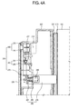
- the first door 200 includes a basket 210, a door main body 220, a pocket unit 230, a handle member 240, and a slider 280 reciprocating between an opening position B and a closing position A (see FIGS. 4A and 4B for the opening and closing positions).
- the basket 210 has a tube shape having an upper opening, and enters and exits the first storage compartment 110a in forward and backward directions.
- the door main body 220 is coupled to a front area of the basket 210.
- the door main body 220 is provided in a planar shape filled with a foaming agent therein, and opens and closes the front opening of the first storage compartment 110a according to entrance and exit of the basket 210.
- a surface of a side of the first storage compartment 110a of the door main body 220, that is, an inner surface of the door main body 220 is coupled to the basket 210.
- a gasket 221 is mounted around a circumferential area in the inner surface of the door main body 220. The gasket 221 is in contact with front surfaces of lateral walls 111 of the first storage compartment 110a. The gasket 221 improves an airtight force of the first door 200 and the first storage compartment 110a.
- the pocket unit 230 is recessed in a surface of the door main body 220. The pocket unit 230 is formed at an upper surface of the main body 220.
- the pocket unit 230 supplies a space to allow a user to open the first door 200.
- the pocket unit 230 has a length in a widthwise direction of the door main body 220, that is, a left and right direction thereof.
- the pocket unit 230 has a length corresponding to the width of the door main body 220.
- a front wall surface of the pocket unit 230 is formed by a door front cover 225 coupled to a front of the door main body 220.
- the handle member 240 is accommodated in the pocket unit 230.
- the handle member 240 includes a lever 250 accommodated in the pocket unit 230, a hinge unit 260 coupling the lever 250 with respect to the door main body 220 to rotate in forward and backward directions, and a pressing unit 270 moving in the opposite direction to the lever 250 about the hinge unit 260 depending on rotation of the lever 250 to press and release the slider 280.
- the lever 250 includes a lever main body 251 disposed in a surface direction of the door main body 220 so that a surface thereof can be distanced from the front wall surface of the pocket unit 230 in the opening position B, and a lever cover 253 bent from an end area of the lever main body 251 to cover between the front wall surface of the pocket unit 230 and the lever main body 251.
- the lever 250 has a length corresponding to the length of the pocket unit 230, i.e., corresponding to the width of the door main body 220.
- the lever main body 251 is provided in a planar shape, and is accommodated in the pocket unit 230.
- a surface of the lever main body 251 is disposed in a surface direction of the door main body 220.
- the lever main body 251 is distanced from the front wall surface of the pocket unit 230, that is, the door front cover 225 by a predetermined interval.
- the lever main body 251 may be provided to total areas along a lengthwise direction of the pocket unit 230.
- the lever main body 251 has a height similar to the front wall surface of the pocket unit 230, that is, the door front cover 225.
- the lever cover 253 is bent and elongated in an outer end area of the lever main body 251, that is, an upper end area.
- the lever cover 253 is bent and elongated forward from the upper end area of the lever main body 251 to cover between the front wall surface of the pocket unit 230 and the lever main body 251.
- the lever cover 253 is provided in a curved surface.
- the lever cover 253 may have a sectional shape of a part of a circular arc about the hinge unit 260. That is, the lever cover 253 covers between the front wall surface of the pocket unit 230 and the lever main body 251 in the closing position A, and rotates about the hinge unit 260 to protrude forward from the door main body 220 when moving from the closing position A to the opening position B. Accordingly, the lever cover 253 can move with maintaining a uniform gap in an up and down direction with respect to the front wall surface of the pocket unit 230, that is, the door front cover 225.
- the hinge unit 260 is provided to a lower part of the lever 250, and couples the lever 250 with respect to the door main body 220 to rotate in the forward and backward directions.
- the hinge unit 260 is provided in a plurality of areas along the lengthwise direction of the lever 250. Accordingly, the hinge unit 260 can strongly support the lever 250 with respect to the door main body 220.
- the hinge unit 260 includes a hinge pivot 261 and a hinge pivot coupling unit 263.
- the hinge pivot 261 is provided at a lower area of the lever main body 251 in the lengthwise direction of the lever 250. That is, the hinge pivot 261 is provided to have an axial direction which is in parallel with the widthwise direction of the door main body 220. The hinge pivot 261 is provided in plural to be distanced along the lengthwise direction of the lever main body 251. The hinge pivot 261 is coupled to the door main body 220 by the hinge pivot coupling unit 263.
- the hinge pivot coupling unit 263 has a hinge pivot accommodating unit 265 and a coupling unit 267.
- the hinge pivot accommodating unit 265 is provided in a ring shape to form a hinge pivot accommodating groove 265a surrounding an outer surface of the hinge pivot 261.
- a hinge pivot accommodating groove 227 facing the hinge pivot coupling unit 263 and coupled thereto to surround the hinge pivot 261 is formed to the door main body 220. That is, the hinge pivot accommodating groove 265a of the hinge pivot coupling unit 263 and the hinge pivot accommodating groove 227 of the door main body 220 are provided in a groove having a semicircular shape section, and are coupled with each other to surround a circumference of the hinge pivot 261.
- the hinge pivot coupling unit 263 formed with one pair of hinge pivot accommodating grooves 265a is provided, and the hinge pivot accommodating groove 227 is formed to the door main body 220 to be coupled face to face to surround the circumference of the hinge pivot 261.
- assembling, disassembling, replacement and repair can be easily performed as compared to the case that a hinge pivot insertion hole (not shown) in which the hinge pivot 261 is coupled is provided to the door main body 220, and the hinge pivot 261 is forcedly inserted therein.
- Lubricating oil is applied to the hinge pivot accommodating grooves 265a and 227. However, lubricating oil may also be applied to the hinge pivot 261. Accordingly, the lever 250 can smoothly rotate, and an operation noise can be reduced.
- the coupling unit 267 is elongated from the hinge pivot accommodating unit 265 in the surface direction of the door main body 220 to be coupled to the door main body 220 by a screw (not shown).
- the hinge pivot coupling unit 263 may further include an engagement unit 269 elongated from the hinge pivot accommodating unit 265 toward the first storage compartment 110a to be engaged to an inner part of the door main body 220.
- the engagement unit 269 allows the hinge pivot 261 to be more strongly supported with respect to the door main body 220.
- the pressing unit 270 moves in the direction opposite to the lever 250 about the hinge unit 260 depending on rotation of the lever 250, and presses and releases the slider 280. That is, the lever 250, the hinge pivot 261 and the pressing unit 270 are integrally formed in the vertical direction. If the lever 250 is rotated forward about the hinge pivot 261, the pressing unit 270 rotates in the same direction as the lever 250 to rotate backward.
- One pair of pressing units 270 are provided to the opposite sides in the widthwise direction of the door main body 220. That is, the pressing unit 270 is provided in a pair to a lower part of the opposite end areas of the lever 250.
- One pair of sliders 280 are provided to the opposite sides in the widthwise direction of the door main body 220. That is, the slider 280 is provided in a pair to correspond to one pair of pressing units 270.
- the slider 280 reciprocates depending on rotation of the hinge member 240 between the opening position B protruding from the door main body 220 to press the main body cabinet 100, and the closing position A accommodated in an inner part of the door main body 220.
- the slider 280 is disposed to an outer area of the gasket 221.
- the slider 280 has a length along the forward and backward directions, and moves between the opening position B and the closing position A depending on pressing and releasing of the pressing unit 270.
- the opening position B is a position of the slider 280 in which the slider 280 receives a backward pressing force from the pressing unit 270 to protrude from an inner surface of the door main body 220 and press the front surfaces of the lateral walls 111 of the first storage compartment 110a, thereby distancing the door main body 220 from the main body cabinet 100.
- the lever 250 rotates forward about the hinge pivot 261
- the pressing unit 270 moves backward.
- the pressing unit 270 presses the slider 280 backward to move to the opening position B.
- the closing position A is a position of the slider 280 in which the pressing force of the pressing unit 270 is withdrawn and the slider 280 is accommodated in an inner part of the door main body 220.
- the lever 250 rotates backward about the hinge pivot 261
- the pressing unit 270 moves forward.
- the pressing unit 270 withdraws the pressing with respect to the slider 280 to move the slider 280 to the closing position A.
- the slider 280 includes a slider head 281 having the same surface direction as the door main body 220 to face the pressing unit 270, and a slider stick 285 extending from the slider head 281 toward the first storage compartment 110a.
- one handle member 240 is enough to make one pair of sliders 280 press the front surfaces of the lateral walls 111 of the first storage compartment 110a, so that the first door 200 can be easily opened by a relatively small force. Further, the slider 280 does not press a front surface of an upper wall 113 of the first storage compartment 110a, but presses the front surfaces of the lateral walls 111, so that the first door can be opened even if the handle member 240 has a short rotating distance.
- the doors 200, 300 and 400 may further include an elastic member 290 supplying an elastic force to the handle member 240 or the slider 280 so that the slider 280 can maintain the closing position A.
- the elastic member 290 is provided as a coil spring supplying an elastic force forward to the slider 280.
- An end part of the elastic member 290 is supported to the door main body 220, and the other end part thereof is supported to the slider 280.
- an elastic member supporting unit 283 accommodating and supporting the other end part of the elastic member 290 is formed to a surface of the slider head 281.
- the second door 300 may have the substantially same configuration as the first door 200.
- the pocket unit 230 of the first door 200 is described to be formed at an upper surface of the door main body 220, but the pocket unit 230 may be formed at a lower surface, or left or right surfaces of the door main body 220.
- the handle member 240 and the slider 280 have the same configurations as above, except the disposition direction thereof.
- the third door 400 may include configurations of a pocket unit 430, a handle member 440 and a slider 480 similar to the first door 200.
- the pocket unit 430, the handle member 440 and the slider 480 of the third door 400 may have the substantially same configurations as the first door 200, except the disposition direction thereof.
- the configurations of the pocket unit 230, the handle member 240 and the slider 280 are described to be mounted to all of the first door 200, the second door 300 and the third door 400, but may be mounted to only the first door 200 and the second door 300 which are the drawer type doors, or may be mounted to only the third door 400 which is the rotation opening and closing type door.
- a standing type kimchi refrigerator including all of the rotating doors and the entrance and exit opening and closing type door is described.
- the embodiments are not limited thereto, and the configurations of the pocket 230, the handle member 240 and the slider 280 may be applied to all types of refrigerators including at least one of the rotating door and the entrance and exit type door.
- FIGS. 4A and 4B are sectional views illustrating an opening and closing operation state of the first door 200 of the refrigerator 1.
- the slider 280 usually maintains the closing position A by an elastic force of the elastic member 290.
- a user inserts a hand in the pocket unit 230, and presses a surface of the lever 250 in a drawing direction of the basket 210, that is, in a forward direction with a force of such a strength as to overcome the elastic force of the elastic member 290.
- the pressing unit 270 presses the slider 280, and the slider 280 protrudes from the door main body 220 to move to the opening position B.
- the gasket 221 is distanced from the main body cabinet 100 by a pressing force of the slider 280, and an internal pressure of the first storage compartment 110a is broken.
- the user further presses forward the surface of the lever 250 to draw the basket 210 from the first storage compartment 110a to a desired position.
- a door can be easily opened by a relatively small force.
- the handle member 240 does not protrude outside the door main body 220, thereby enhancing an external appearance.
- the present embodiment provides a refrigerator allowing a user to easily open a door with a relatively small force, and enhancing beauty of an external appearance.
Landscapes
- Engineering & Computer Science (AREA)
- Chemical & Material Sciences (AREA)
- Combustion & Propulsion (AREA)
- Physics & Mathematics (AREA)
- Mechanical Engineering (AREA)
- Thermal Sciences (AREA)
- General Engineering & Computer Science (AREA)
- Refrigerator Housings (AREA)
Applications Claiming Priority (2)
| Application Number | Priority Date | Filing Date | Title |
|---|---|---|---|
| KR20090080064 | 2009-08-27 | ||
| KR20090101921A KR101510759B1 (ko) | 2009-10-26 | 2009-10-26 | 냉장고 |
Publications (3)
| Publication Number | Publication Date |
|---|---|
| EP2299213A2 true EP2299213A2 (de) | 2011-03-23 |
| EP2299213A3 EP2299213A3 (de) | 2017-05-31 |
| EP2299213B1 EP2299213B1 (de) | 2018-08-01 |
Family
ID=43303263
Family Applications (1)
| Application Number | Title | Priority Date | Filing Date |
|---|---|---|---|
| EP10162902.0A Not-in-force EP2299213B1 (de) | 2009-08-27 | 2010-05-17 | Kühlanlage |
Country Status (3)
| Country | Link |
|---|---|
| US (1) | US8328301B2 (de) |
| EP (1) | EP2299213B1 (de) |
| CN (2) | CN105020958B (de) |
Cited By (2)
| Publication number | Priority date | Publication date | Assignee | Title |
|---|---|---|---|---|
| WO2014202500A1 (de) * | 2013-06-19 | 2014-12-24 | BSH Bosch und Siemens Hausgeräte GmbH | Tür für ein haushaltsgerät mit einer abdeckschale sowie haushaltsgerät mit einer derartigen tür |
| EP4379298A4 (de) * | 2021-12-23 | 2025-01-08 | Samsung Electronics Co., Ltd. | Türöffnungsvorrichtung und kühlschrank damit |
Families Citing this family (40)
| Publication number | Priority date | Publication date | Assignee | Title |
|---|---|---|---|---|
| CN101608855B (zh) * | 2008-06-20 | 2012-07-04 | 海尔集团公司 | 电冰箱 |
| CN102269508B (zh) * | 2011-09-15 | 2013-05-22 | 合肥美的荣事达电冰箱有限公司 | 用于冰箱的门体和具有该门体的冰箱 |
| WO2013057259A2 (en) * | 2011-10-21 | 2013-04-25 | Arcelik Anonim Sirketi | A cooling device comprising a door opening mechanism |
| KR101654383B1 (ko) * | 2011-11-09 | 2016-09-06 | 엘지전자 주식회사 | 냉장고 |
| KR20130115546A (ko) * | 2012-04-12 | 2013-10-22 | 삼성전자주식회사 | 슬라이딩 장치 및 이를 갖는 냉장고 |
| US9506685B2 (en) * | 2012-04-16 | 2016-11-29 | Lg Electronics Inc. | Refrigerator |
| KR101918059B1 (ko) * | 2012-07-23 | 2018-11-13 | 엘지전자 주식회사 | 드로어 밀폐유지장치를 구비한 냉장고 |
| US9121633B2 (en) * | 2012-07-23 | 2015-09-01 | Lg Electronics Inc. | Refrigerator |
| DE102013103820B4 (de) * | 2013-04-16 | 2023-11-23 | Miele & Cie. Kg | Kühlgerät |
| US8944537B1 (en) * | 2013-10-17 | 2015-02-03 | Edwin Dizon Manalang | Drawer latch assembly a toolbox assembly |
| US9181731B2 (en) * | 2013-10-17 | 2015-11-10 | Larry Mitchell Grela | Drawer latch assembly and a toolbox assembly |
| US9388609B2 (en) * | 2013-10-17 | 2016-07-12 | Larry Mitchell Grela | Drawer latch assembly and toolbox assembly |
| CN104279809A (zh) * | 2014-09-29 | 2015-01-14 | 青岛海尔股份有限公司 | 冰箱 |
| US9759479B2 (en) | 2015-10-22 | 2017-09-12 | Whirlpool Corporation | Appliance modular system for incorporating a pantry compartment within an appliance |
| US10006693B2 (en) | 2015-10-22 | 2018-06-26 | Whirlpool Corporation | Appliance modular system for incorporating a pantry compartment within an appliance |
| DE102015221885A1 (de) | 2015-11-06 | 2017-05-24 | BSH Hausgeräte GmbH | Tür mit einem Türrahmen und einem Griffmuldenelement sowie Haushaltskältegerät mit einer derartigen Tür |
| DE102015222732A1 (de) | 2015-11-18 | 2017-05-18 | BSH Hausgeräte GmbH | Haushaltsgerät mit einer Gerätekomponente mit von oben greifbarer Griffmulde |
| US9752817B2 (en) | 2015-12-18 | 2017-09-05 | Whirlpool Corporation | Door/drawer panel adjustment mechanism for an appliance |
| US10684063B2 (en) | 2015-12-28 | 2020-06-16 | Whirlpool Corporation | Easy open drawer/door with rotating handle |
| KR101858238B1 (ko) * | 2016-05-17 | 2018-05-16 | 주식회사 대우전자 | 도어 개방장치를 포함하는 냉장고 |
| CN106580150B (zh) * | 2016-12-28 | 2019-01-18 | 青岛海尔股份有限公司 | 定量分配装置及具有其的冰箱 |
| KR102607767B1 (ko) * | 2017-07-21 | 2023-11-30 | 엘지전자 주식회사 | 냉장고 및 냉장고 도어 개방장치 |
| KR102892222B1 (ko) | 2019-07-12 | 2025-11-27 | 엘지전자 주식회사 | 냉장고 |
| KR102812236B1 (ko) * | 2019-07-12 | 2025-05-22 | 엘지전자 주식회사 | 냉장고 |
| CN112212574B (zh) | 2019-07-12 | 2022-06-24 | Lg电子株式会社 | 冰箱 |
| KR20210007648A (ko) | 2019-07-12 | 2021-01-20 | 엘지전자 주식회사 | 냉장고 |
| KR102836705B1 (ko) | 2019-07-12 | 2025-07-18 | 엘지전자 주식회사 | 냉장고 |
| KR102880310B1 (ko) | 2019-07-12 | 2025-11-03 | 엘지전자 주식회사 | 서랍식 도어를 포함하는 냉장고 |
| KR102799833B1 (ko) | 2019-07-12 | 2025-04-23 | 엘지전자 주식회사 | 냉장고 |
| KR20210007644A (ko) | 2019-07-12 | 2021-01-20 | 엘지전자 주식회사 | 냉장고 |
| KR20210007642A (ko) | 2019-07-12 | 2021-01-20 | 엘지전자 주식회사 | 서랍식 도어를 포함하는 냉장고 |
| KR102892694B1 (ko) | 2019-07-12 | 2025-11-27 | 엘지전자 주식회사 | 냉장고 |
| KR102805224B1 (ko) | 2019-07-15 | 2025-05-12 | 엘지전자 주식회사 | 냉장고 및 냉장고의 제어방법 |
| KR20210008709A (ko) | 2019-07-15 | 2021-01-25 | 엘지전자 주식회사 | 냉장고 및 냉장고의 제어방법 |
| KR102814137B1 (ko) * | 2020-01-07 | 2025-05-28 | 엘지전자 주식회사 | 냉장고 |
| CN114001508B (zh) * | 2020-07-28 | 2024-09-06 | 海信冰箱有限公司 | 一种冰箱 |
| KR20220099854A (ko) * | 2021-01-07 | 2022-07-14 | 엘지전자 주식회사 | 냉장고 |
| USD1120989S1 (en) * | 2021-02-08 | 2026-03-31 | Qingdao Haier Refrigerator Co., Ltd. | Door body for refrigerator |
| KR20240086995A (ko) * | 2022-12-12 | 2024-06-19 | 엘지전자 주식회사 | 냉장고 |
| KR20240130336A (ko) * | 2023-02-22 | 2024-08-29 | 엘지전자 주식회사 | 냉장고 |
Family Cites Families (20)
| Publication number | Priority date | Publication date | Assignee | Title |
|---|---|---|---|---|
| US2659115A (en) * | 1950-03-27 | 1953-11-17 | Jervis Corp | Magnetic door seal |
| KR0139299Y1 (ko) * | 1996-08-14 | 1999-05-15 | 김광호 | 냉장고의 도어장치 |
| JP3045983B2 (ja) * | 1996-10-25 | 2000-05-29 | 三星電子株式会社 | 冷蔵庫の扉装置 |
| DE19652828A1 (de) * | 1996-12-18 | 1998-06-25 | Bosch Siemens Hausgeraete | Kältegerät |
| USD430174S (en) * | 1998-02-27 | 2000-08-29 | Multibras S/A Electrodomesticos | End assembly for doors of refrigerators, refrigerator freezers and freezers |
| CN1158508C (zh) * | 1998-08-04 | 2004-07-21 | 松下冷机株式会社 | 冰箱门开启器 |
| CN2434627Y (zh) * | 2000-06-09 | 2001-06-13 | 合肥美菱股份有限公司 | 家用电冰箱开门助力装置 |
| CN2467983Y (zh) * | 2000-12-20 | 2001-12-26 | 合肥美菱股份有限公司 | 家用电冰箱开门助力装置 |
| US7097213B2 (en) * | 2001-10-22 | 2006-08-29 | Thetford Corporation | Latching arrangement for a refrigerator door |
| USD507284S1 (en) * | 2004-03-11 | 2005-07-12 | Lg Electronics Inc. | Refrigerator |
| US20050200253A1 (en) * | 2004-03-11 | 2005-09-15 | John Wissinger | Spring biased latching arrangement for a refrigerator door |
| JP2005337681A (ja) * | 2004-05-31 | 2005-12-08 | Matsushita Electric Ind Co Ltd | 冷蔵庫扉のハンドル |
| JP4289499B2 (ja) * | 2004-09-06 | 2009-07-01 | 城南鋼鉄工業株式会社 | 扉のロック機構 |
| CN100529615C (zh) * | 2005-01-21 | 2009-08-19 | 利布赫尔家用器具奥克森豪森股份有限公司 | 用于冰箱和/或冷柜的门把 |
| DE202005002960U1 (de) * | 2005-01-21 | 2006-06-01 | Liebherr-Hausgeräte Ochsenhausen GmbH | Kühl- und/oder Gefrierschranktürgriff |
| KR20080001006A (ko) * | 2006-06-28 | 2008-01-03 | 삼성전자주식회사 | 냉장고 |
| KR20080100553A (ko) * | 2007-05-14 | 2008-11-19 | 엘지전자 주식회사 | 냉장고의 도어개방구조 |
| KR101484039B1 (ko) * | 2008-01-11 | 2015-01-20 | 삼성전자 주식회사 | 냉장고의 도어 개방장치 |
| KR101600310B1 (ko) * | 2008-02-20 | 2016-03-09 | 삼성전자 주식회사 | 냉장고 |
| KR101528729B1 (ko) * | 2008-10-28 | 2015-06-30 | 삼성전자 주식회사 | 냉장고 |
-
2010
- 2010-03-16 US US12/659,661 patent/US8328301B2/en active Active
- 2010-05-17 EP EP10162902.0A patent/EP2299213B1/de not_active Not-in-force
- 2010-07-07 CN CN201510431322.6A patent/CN105020958B/zh not_active Expired - Fee Related
- 2010-07-07 CN CN201010224935.XA patent/CN102003862B/zh not_active Expired - Fee Related
Non-Patent Citations (1)
| Title |
|---|
| None |
Cited By (4)
| Publication number | Priority date | Publication date | Assignee | Title |
|---|---|---|---|---|
| WO2014202500A1 (de) * | 2013-06-19 | 2014-12-24 | BSH Bosch und Siemens Hausgeräte GmbH | Tür für ein haushaltsgerät mit einer abdeckschale sowie haushaltsgerät mit einer derartigen tür |
| CN105408706A (zh) * | 2013-06-19 | 2016-03-16 | Bsh家用电器有限公司 | 具有罩壳的用于家用器具的门以及具有这样的门的家用器具 |
| EP4379298A4 (de) * | 2021-12-23 | 2025-01-08 | Samsung Electronics Co., Ltd. | Türöffnungsvorrichtung und kühlschrank damit |
| US12410967B2 (en) | 2021-12-23 | 2025-09-09 | Samsung Electronics Co., Ltd. | Door opening device and refrigerator having the same |
Also Published As
| Publication number | Publication date |
|---|---|
| CN102003862A (zh) | 2011-04-06 |
| US8328301B2 (en) | 2012-12-11 |
| US20110050066A1 (en) | 2011-03-03 |
| EP2299213A3 (de) | 2017-05-31 |
| CN105020958B (zh) | 2018-11-06 |
| EP2299213B1 (de) | 2018-08-01 |
| CN102003862B (zh) | 2015-08-19 |
| CN105020958A (zh) | 2015-11-04 |
Similar Documents
| Publication | Publication Date | Title |
|---|---|---|
| EP2299213B1 (de) | Kühlanlage | |
| EP2657632B1 (de) | Kühlschrank und Montageverfahren einer Griffanordnung | |
| EP2212634B1 (de) | Kühlschrank mit einer schienenanordnung | |
| EP2175218B1 (de) | Kühlanlage | |
| KR102766379B1 (ko) | 냉장고 | |
| US8398185B2 (en) | Opening device for refrigerator | |
| EP2957844B1 (de) | Scharnier für einen kühlschrank und verfahren zur herstellung davon | |
| KR20120124693A (ko) | 냉장고 및 냉장고 도어 | |
| KR102120103B1 (ko) | 저장용기 및 이를 포함하는 냉장고 | |
| KR101741392B1 (ko) | 자동 인출 선반을 포함하는 냉장고 | |
| AU2015228154A1 (en) | Storage cabinet and refrigerator | |
| US20070085457A1 (en) | Refrigerator | |
| EP4300019A1 (de) | Kühlschrank | |
| KR100726453B1 (ko) | 냉장고 | |
| US7543897B2 (en) | Door opening prevention device for refrigerator | |
| US12578139B2 (en) | Refrigerator | |
| KR101668707B1 (ko) | 냉장고 도어 | |
| KR101510759B1 (ko) | 냉장고 | |
| KR20120009651A (ko) | 냉장고 | |
| KR20090074442A (ko) | 냉장고의 도어 개방장치 | |
| KR20230096368A (ko) | 도어 개방장치 및 이를 갖는 냉장고 | |
| KR20230101423A (ko) | 냉장고 |
Legal Events
| Date | Code | Title | Description |
|---|---|---|---|
| PUAI | Public reference made under article 153(3) epc to a published international application that has entered the european phase |
Free format text: ORIGINAL CODE: 0009012 |
|
| AK | Designated contracting states |
Kind code of ref document: A2 Designated state(s): AL AT BE BG CH CY CZ DE DK EE ES FI FR GB GR HR HU IE IS IT LI LT LU LV MC MK MT NL NO PL PT RO SE SI SK SM TR |
|
| AX | Request for extension of the european patent |
Extension state: BA ME RS |
|
| RAP1 | Party data changed (applicant data changed or rights of an application transferred) |
Owner name: SAMSUNG ELECTRONICS CO., LTD. |
|
| PUAL | Search report despatched |
Free format text: ORIGINAL CODE: 0009013 |
|
| AK | Designated contracting states |
Kind code of ref document: A3 Designated state(s): AL AT BE BG CH CY CZ DE DK EE ES FI FR GB GR HR HU IE IS IT LI LT LU LV MC MK MT NL NO PL PT RO SE SI SK SM TR |
|
| AX | Request for extension of the european patent |
Extension state: BA ME RS |
|
| RIC1 | Information provided on ipc code assigned before grant |
Ipc: F25D 23/02 20060101AFI20170421BHEP |
|
| STAA | Information on the status of an ep patent application or granted ep patent |
Free format text: STATUS: REQUEST FOR EXAMINATION WAS MADE |
|
| 17P | Request for examination filed |
Effective date: 20170808 |
|
| RBV | Designated contracting states (corrected) |
Designated state(s): AL AT BE BG CH CY CZ DE DK EE ES FI FR GB GR HR HU IE IS IT LI LT LU LV MC MK MT NL NO PL PT RO SE SI SK SM TR |
|
| GRAP | Despatch of communication of intention to grant a patent |
Free format text: ORIGINAL CODE: EPIDOSNIGR1 |
|
| STAA | Information on the status of an ep patent application or granted ep patent |
Free format text: STATUS: GRANT OF PATENT IS INTENDED |
|
| INTG | Intention to grant announced |
Effective date: 20180227 |
|
| GRAS | Grant fee paid |
Free format text: ORIGINAL CODE: EPIDOSNIGR3 |
|
| GRAA | (expected) grant |
Free format text: ORIGINAL CODE: 0009210 |
|
| STAA | Information on the status of an ep patent application or granted ep patent |
Free format text: STATUS: THE PATENT HAS BEEN GRANTED |
|
| AK | Designated contracting states |
Kind code of ref document: B1 Designated state(s): AL AT BE BG CH CY CZ DE DK EE ES FI FR GB GR HR HU IE IS IT LI LT LU LV MC MK MT NL NO PL PT RO SE SI SK SM TR |
|
| REG | Reference to a national code |
Ref country code: GB Ref legal event code: FG4D |
|
| REG | Reference to a national code |
Ref country code: CH Ref legal event code: EP Ref country code: AT Ref legal event code: REF Ref document number: 1024784 Country of ref document: AT Kind code of ref document: T Effective date: 20180815 |
|
| REG | Reference to a national code |
Ref country code: IE Ref legal event code: FG4D |
|
| REG | Reference to a national code |
Ref country code: DE Ref legal event code: R096 Ref document number: 602010052293 Country of ref document: DE |
|
| REG | Reference to a national code |
Ref country code: NL Ref legal event code: MP Effective date: 20180801 |
|
| REG | Reference to a national code |
Ref country code: LT Ref legal event code: MG4D |
|
| REG | Reference to a national code |
Ref country code: AT Ref legal event code: MK05 Ref document number: 1024784 Country of ref document: AT Kind code of ref document: T Effective date: 20180801 |
|
| PG25 | Lapsed in a contracting state [announced via postgrant information from national office to epo] |
Ref country code: LT Free format text: LAPSE BECAUSE OF FAILURE TO SUBMIT A TRANSLATION OF THE DESCRIPTION OR TO PAY THE FEE WITHIN THE PRESCRIBED TIME-LIMIT Effective date: 20180801 Ref country code: PL Free format text: LAPSE BECAUSE OF FAILURE TO SUBMIT A TRANSLATION OF THE DESCRIPTION OR TO PAY THE FEE WITHIN THE PRESCRIBED TIME-LIMIT Effective date: 20180801 Ref country code: NL Free format text: LAPSE BECAUSE OF FAILURE TO SUBMIT A TRANSLATION OF THE DESCRIPTION OR TO PAY THE FEE WITHIN THE PRESCRIBED TIME-LIMIT Effective date: 20180801 Ref country code: GR Free format text: LAPSE BECAUSE OF FAILURE TO SUBMIT A TRANSLATION OF THE DESCRIPTION OR TO PAY THE FEE WITHIN THE PRESCRIBED TIME-LIMIT Effective date: 20181102 Ref country code: NO Free format text: LAPSE BECAUSE OF FAILURE TO SUBMIT A TRANSLATION OF THE DESCRIPTION OR TO PAY THE FEE WITHIN THE PRESCRIBED TIME-LIMIT Effective date: 20181101 Ref country code: BG Free format text: LAPSE BECAUSE OF FAILURE TO SUBMIT A TRANSLATION OF THE DESCRIPTION OR TO PAY THE FEE WITHIN THE PRESCRIBED TIME-LIMIT Effective date: 20181101 Ref country code: SE Free format text: LAPSE BECAUSE OF FAILURE TO SUBMIT A TRANSLATION OF THE DESCRIPTION OR TO PAY THE FEE WITHIN THE PRESCRIBED TIME-LIMIT Effective date: 20180801 Ref country code: AT Free format text: LAPSE BECAUSE OF FAILURE TO SUBMIT A TRANSLATION OF THE DESCRIPTION OR TO PAY THE FEE WITHIN THE PRESCRIBED TIME-LIMIT Effective date: 20180801 Ref country code: IS Free format text: LAPSE BECAUSE OF FAILURE TO SUBMIT A TRANSLATION OF THE DESCRIPTION OR TO PAY THE FEE WITHIN THE PRESCRIBED TIME-LIMIT Effective date: 20181201 Ref country code: FI Free format text: LAPSE BECAUSE OF FAILURE TO SUBMIT A TRANSLATION OF THE DESCRIPTION OR TO PAY THE FEE WITHIN THE PRESCRIBED TIME-LIMIT Effective date: 20180801 |
|
| PG25 | Lapsed in a contracting state [announced via postgrant information from national office to epo] |
Ref country code: ES Free format text: LAPSE BECAUSE OF FAILURE TO SUBMIT A TRANSLATION OF THE DESCRIPTION OR TO PAY THE FEE WITHIN THE PRESCRIBED TIME-LIMIT Effective date: 20180801 Ref country code: HR Free format text: LAPSE BECAUSE OF FAILURE TO SUBMIT A TRANSLATION OF THE DESCRIPTION OR TO PAY THE FEE WITHIN THE PRESCRIBED TIME-LIMIT Effective date: 20180801 Ref country code: AL Free format text: LAPSE BECAUSE OF FAILURE TO SUBMIT A TRANSLATION OF THE DESCRIPTION OR TO PAY THE FEE WITHIN THE PRESCRIBED TIME-LIMIT Effective date: 20180801 Ref country code: LV Free format text: LAPSE BECAUSE OF FAILURE TO SUBMIT A TRANSLATION OF THE DESCRIPTION OR TO PAY THE FEE WITHIN THE PRESCRIBED TIME-LIMIT Effective date: 20180801 |
|
| PG25 | Lapsed in a contracting state [announced via postgrant information from national office to epo] |
Ref country code: IT Free format text: LAPSE BECAUSE OF FAILURE TO SUBMIT A TRANSLATION OF THE DESCRIPTION OR TO PAY THE FEE WITHIN THE PRESCRIBED TIME-LIMIT Effective date: 20180801 Ref country code: EE Free format text: LAPSE BECAUSE OF FAILURE TO SUBMIT A TRANSLATION OF THE DESCRIPTION OR TO PAY THE FEE WITHIN THE PRESCRIBED TIME-LIMIT Effective date: 20180801 Ref country code: RO Free format text: LAPSE BECAUSE OF FAILURE TO SUBMIT A TRANSLATION OF THE DESCRIPTION OR TO PAY THE FEE WITHIN THE PRESCRIBED TIME-LIMIT Effective date: 20180801 Ref country code: CZ Free format text: LAPSE BECAUSE OF FAILURE TO SUBMIT A TRANSLATION OF THE DESCRIPTION OR TO PAY THE FEE WITHIN THE PRESCRIBED TIME-LIMIT Effective date: 20180801 |
|
| REG | Reference to a national code |
Ref country code: DE Ref legal event code: R097 Ref document number: 602010052293 Country of ref document: DE |
|
| PG25 | Lapsed in a contracting state [announced via postgrant information from national office to epo] |
Ref country code: DK Free format text: LAPSE BECAUSE OF FAILURE TO SUBMIT A TRANSLATION OF THE DESCRIPTION OR TO PAY THE FEE WITHIN THE PRESCRIBED TIME-LIMIT Effective date: 20180801 Ref country code: SK Free format text: LAPSE BECAUSE OF FAILURE TO SUBMIT A TRANSLATION OF THE DESCRIPTION OR TO PAY THE FEE WITHIN THE PRESCRIBED TIME-LIMIT Effective date: 20180801 Ref country code: SM Free format text: LAPSE BECAUSE OF FAILURE TO SUBMIT A TRANSLATION OF THE DESCRIPTION OR TO PAY THE FEE WITHIN THE PRESCRIBED TIME-LIMIT Effective date: 20180801 |
|
| PLBE | No opposition filed within time limit |
Free format text: ORIGINAL CODE: 0009261 |
|
| STAA | Information on the status of an ep patent application or granted ep patent |
Free format text: STATUS: NO OPPOSITION FILED WITHIN TIME LIMIT |
|
| 26N | No opposition filed |
Effective date: 20190503 |
|
| PG25 | Lapsed in a contracting state [announced via postgrant information from national office to epo] |
Ref country code: SI Free format text: LAPSE BECAUSE OF FAILURE TO SUBMIT A TRANSLATION OF THE DESCRIPTION OR TO PAY THE FEE WITHIN THE PRESCRIBED TIME-LIMIT Effective date: 20180801 |
|
| REG | Reference to a national code |
Ref country code: CH Ref legal event code: PL |
|
| PG25 | Lapsed in a contracting state [announced via postgrant information from national office to epo] |
Ref country code: MC Free format text: LAPSE BECAUSE OF FAILURE TO SUBMIT A TRANSLATION OF THE DESCRIPTION OR TO PAY THE FEE WITHIN THE PRESCRIBED TIME-LIMIT Effective date: 20180801 Ref country code: CH Free format text: LAPSE BECAUSE OF NON-PAYMENT OF DUE FEES Effective date: 20190531 Ref country code: LI Free format text: LAPSE BECAUSE OF NON-PAYMENT OF DUE FEES Effective date: 20190531 |
|
| REG | Reference to a national code |
Ref country code: BE Ref legal event code: MM Effective date: 20190531 |
|
| PG25 | Lapsed in a contracting state [announced via postgrant information from national office to epo] |
Ref country code: LU Free format text: LAPSE BECAUSE OF NON-PAYMENT OF DUE FEES Effective date: 20190517 |
|
| PG25 | Lapsed in a contracting state [announced via postgrant information from national office to epo] |
Ref country code: TR Free format text: LAPSE BECAUSE OF FAILURE TO SUBMIT A TRANSLATION OF THE DESCRIPTION OR TO PAY THE FEE WITHIN THE PRESCRIBED TIME-LIMIT Effective date: 20180801 |
|
| PG25 | Lapsed in a contracting state [announced via postgrant information from national office to epo] |
Ref country code: IE Free format text: LAPSE BECAUSE OF NON-PAYMENT OF DUE FEES Effective date: 20190517 |
|
| PG25 | Lapsed in a contracting state [announced via postgrant information from national office to epo] |
Ref country code: BE Free format text: LAPSE BECAUSE OF NON-PAYMENT OF DUE FEES Effective date: 20190531 |
|
| PG25 | Lapsed in a contracting state [announced via postgrant information from national office to epo] |
Ref country code: PT Free format text: LAPSE BECAUSE OF FAILURE TO SUBMIT A TRANSLATION OF THE DESCRIPTION OR TO PAY THE FEE WITHIN THE PRESCRIBED TIME-LIMIT Effective date: 20181201 |
|
| PG25 | Lapsed in a contracting state [announced via postgrant information from national office to epo] |
Ref country code: CY Free format text: LAPSE BECAUSE OF FAILURE TO SUBMIT A TRANSLATION OF THE DESCRIPTION OR TO PAY THE FEE WITHIN THE PRESCRIBED TIME-LIMIT Effective date: 20180801 |
|
| PG25 | Lapsed in a contracting state [announced via postgrant information from national office to epo] |
Ref country code: HU Free format text: LAPSE BECAUSE OF FAILURE TO SUBMIT A TRANSLATION OF THE DESCRIPTION OR TO PAY THE FEE WITHIN THE PRESCRIBED TIME-LIMIT; INVALID AB INITIO Effective date: 20100517 Ref country code: MT Free format text: LAPSE BECAUSE OF FAILURE TO SUBMIT A TRANSLATION OF THE DESCRIPTION OR TO PAY THE FEE WITHIN THE PRESCRIBED TIME-LIMIT Effective date: 20180801 |
|
| PGFP | Annual fee paid to national office [announced via postgrant information from national office to epo] |
Ref country code: FR Payment date: 20210423 Year of fee payment: 12 |
|
| PG25 | Lapsed in a contracting state [announced via postgrant information from national office to epo] |
Ref country code: MK Free format text: LAPSE BECAUSE OF FAILURE TO SUBMIT A TRANSLATION OF THE DESCRIPTION OR TO PAY THE FEE WITHIN THE PRESCRIBED TIME-LIMIT Effective date: 20180801 |
|
| PG25 | Lapsed in a contracting state [announced via postgrant information from national office to epo] |
Ref country code: FR Free format text: LAPSE BECAUSE OF NON-PAYMENT OF DUE FEES Effective date: 20220531 |
|
| PGFP | Annual fee paid to national office [announced via postgrant information from national office to epo] |
Ref country code: DE Payment date: 20230420 Year of fee payment: 14 |
|
| PGFP | Annual fee paid to national office [announced via postgrant information from national office to epo] |
Ref country code: GB Payment date: 20230420 Year of fee payment: 14 |
|
| REG | Reference to a national code |
Ref country code: DE Ref legal event code: R119 Ref document number: 602010052293 Country of ref document: DE |
|
| GBPC | Gb: european patent ceased through non-payment of renewal fee |
Effective date: 20240517 |
|
| PG25 | Lapsed in a contracting state [announced via postgrant information from national office to epo] |
Ref country code: DE Free format text: LAPSE BECAUSE OF NON-PAYMENT OF DUE FEES Effective date: 20241203 |
|
| PG25 | Lapsed in a contracting state [announced via postgrant information from national office to epo] |
Ref country code: GB Free format text: LAPSE BECAUSE OF NON-PAYMENT OF DUE FEES Effective date: 20240517 |