EP2299227A2 - Röhrenwärmetauscher - Google Patents
Röhrenwärmetauscher Download PDFInfo
- Publication number
- EP2299227A2 EP2299227A2 EP10171888A EP10171888A EP2299227A2 EP 2299227 A2 EP2299227 A2 EP 2299227A2 EP 10171888 A EP10171888 A EP 10171888A EP 10171888 A EP10171888 A EP 10171888A EP 2299227 A2 EP2299227 A2 EP 2299227A2
- Authority
- EP
- European Patent Office
- Prior art keywords
- tube
- heat exchanger
- tubular heat
- product
- swirls
- Prior art date
- Legal status (The legal status is an assumption and is not a legal conclusion. Google has not performed a legal analysis and makes no representation as to the accuracy of the status listed.)
- Granted
Links
Images
Classifications
-
- F—MECHANICAL ENGINEERING; LIGHTING; HEATING; WEAPONS; BLASTING
- F28—HEAT EXCHANGE IN GENERAL
- F28F—DETAILS OF HEAT-EXCHANGE AND HEAT-TRANSFER APPARATUS, OF GENERAL APPLICATION
- F28F1/00—Tubular elements; Assemblies of tubular elements
- F28F1/10—Tubular elements and assemblies thereof with means for increasing heat-transfer area, e.g. with fins, with projections, with recesses
- F28F1/12—Tubular elements and assemblies thereof with means for increasing heat-transfer area, e.g. with fins, with projections, with recesses the means being only outside the tubular element
- F28F1/34—Tubular elements and assemblies thereof with means for increasing heat-transfer area, e.g. with fins, with projections, with recesses the means being only outside the tubular element and extending obliquely
- F28F1/36—Tubular elements and assemblies thereof with means for increasing heat-transfer area, e.g. with fins, with projections, with recesses the means being only outside the tubular element and extending obliquely the means being helically wound fins or wire spirals
-
- F—MECHANICAL ENGINEERING; LIGHTING; HEATING; WEAPONS; BLASTING
- F28—HEAT EXCHANGE IN GENERAL
- F28D—HEAT-EXCHANGE APPARATUS, NOT PROVIDED FOR IN ANOTHER SUBCLASS, IN WHICH THE HEAT-EXCHANGE MEDIA DO NOT COME INTO DIRECT CONTACT
- F28D7/00—Heat-exchange apparatus having stationary tubular conduit assemblies for both heat-exchange media, the media being in contact with different sides of a conduit wall
- F28D7/10—Heat-exchange apparatus having stationary tubular conduit assemblies for both heat-exchange media, the media being in contact with different sides of a conduit wall the conduits being arranged one within the other, e.g. concentrically
- F28D7/106—Heat-exchange apparatus having stationary tubular conduit assemblies for both heat-exchange media, the media being in contact with different sides of a conduit wall the conduits being arranged one within the other, e.g. concentrically consisting of two coaxial conduits or modules of two coaxial conduits
-
- F—MECHANICAL ENGINEERING; LIGHTING; HEATING; WEAPONS; BLASTING
- F28—HEAT EXCHANGE IN GENERAL
- F28F—DETAILS OF HEAT-EXCHANGE AND HEAT-TRANSFER APPARATUS, OF GENERAL APPLICATION
- F28F1/00—Tubular elements; Assemblies of tubular elements
- F28F1/10—Tubular elements and assemblies thereof with means for increasing heat-transfer area, e.g. with fins, with projections, with recesses
- F28F1/40—Tubular elements and assemblies thereof with means for increasing heat-transfer area, e.g. with fins, with projections, with recesses the means being only inside the tubular element
-
- F—MECHANICAL ENGINEERING; LIGHTING; HEATING; WEAPONS; BLASTING
- F28—HEAT EXCHANGE IN GENERAL
- F28F—DETAILS OF HEAT-EXCHANGE AND HEAT-TRANSFER APPARATUS, OF GENERAL APPLICATION
- F28F1/00—Tubular elements; Assemblies of tubular elements
- F28F1/10—Tubular elements and assemblies thereof with means for increasing heat-transfer area, e.g. with fins, with projections, with recesses
- F28F1/42—Tubular elements and assemblies thereof with means for increasing heat-transfer area, e.g. with fins, with projections, with recesses the means being both outside and inside the tubular element
- F28F1/424—Means comprising outside portions integral with inside portions
- F28F1/426—Means comprising outside portions integral with inside portions the outside portions and the inside portions forming parts of complementary shape, e.g. concave and convex
-
- F—MECHANICAL ENGINEERING; LIGHTING; HEATING; WEAPONS; BLASTING
- F28—HEAT EXCHANGE IN GENERAL
- F28F—DETAILS OF HEAT-EXCHANGE AND HEAT-TRANSFER APPARATUS, OF GENERAL APPLICATION
- F28F13/00—Arrangements for modifying heat-transfer, e.g. increasing, decreasing
- F28F13/06—Arrangements for modifying heat-transfer, e.g. increasing, decreasing by affecting the pattern of flow of the heat-exchange media
- F28F13/12—Arrangements for modifying heat-transfer, e.g. increasing, decreasing by affecting the pattern of flow of the heat-exchange media by creating turbulence, e.g. by stirring, by increasing the force of circulation
-
- F—MECHANICAL ENGINEERING; LIGHTING; HEATING; WEAPONS; BLASTING
- F28—HEAT EXCHANGE IN GENERAL
- F28D—HEAT-EXCHANGE APPARATUS, NOT PROVIDED FOR IN ANOTHER SUBCLASS, IN WHICH THE HEAT-EXCHANGE MEDIA DO NOT COME INTO DIRECT CONTACT
- F28D21/00—Heat-exchange apparatus not covered by any of the groups F28D1/00 - F28D20/00
- F28D2021/0019—Other heat exchangers for particular applications; Heat exchange systems not otherwise provided for
- F28D2021/0042—Other heat exchangers for particular applications; Heat exchange systems not otherwise provided for for foodstuffs
-
- F—MECHANICAL ENGINEERING; LIGHTING; HEATING; WEAPONS; BLASTING
- F28—HEAT EXCHANGE IN GENERAL
- F28D—HEAT-EXCHANGE APPARATUS, NOT PROVIDED FOR IN ANOTHER SUBCLASS, IN WHICH THE HEAT-EXCHANGE MEDIA DO NOT COME INTO DIRECT CONTACT
- F28D21/00—Heat-exchange apparatus not covered by any of the groups F28D1/00 - F28D20/00
- F28D2021/0019—Other heat exchangers for particular applications; Heat exchange systems not otherwise provided for
- F28D2021/0098—Other heat exchangers for particular applications; Heat exchange systems not otherwise provided for for viscous or semi-liquid materials, e.g. for processing sludge
-
- F—MECHANICAL ENGINEERING; LIGHTING; HEATING; WEAPONS; BLASTING
- F28—HEAT EXCHANGE IN GENERAL
- F28F—DETAILS OF HEAT-EXCHANGE AND HEAT-TRANSFER APPARATUS, OF GENERAL APPLICATION
- F28F19/00—Preventing the formation of deposits or corrosion, e.g. by using filters or scrapers
Definitions
- the invention relates to a tubular heat exchanger of the type specified in the preamble of claim 1 and an inner and / or jacket tube of such a tubular heat exchanger.
- Out DE 600 19 635 T2 is a tube heat exchanger for the treatment of juices with fibers and / or particles known in which simply twisted inner and / or outer tubes are used.
- the helix angle is shown at about 45 °, while the helix angle in the jacket tube at about 75 °, in each case based on the tube axis, is shown.
- this tubular heat exchanger it is disadvantageous that, in order to increase the heat transfer, it is necessary to accept very high pressure loss with a constant flow area and the boundary layer of the flow is excited to strong rotation at the swirlings extending at the same helix angle to the pipe axis. This requires very high, possibly for the product disadvantageous, delivery pressure for the treatment of the product in the tubular heat exchanger.
- Out DE 102 56 232 B4 is a tube heat exchanger for UHT treatment of milk and dairy for sterilization known.
- the jacket tube is a smooth tube.
- Only the inner tubes may be thoroughdrallrohre, in which the multi-course mutually opposing swirls intersect at angles between 25 ° and 35 ° along the tube axis, ie with helix angles between 65 ° and 55 °.
- This angle range is specially adapted to milk and milk products, which are very prone to build up on the contacted surface. Therefore, the swirls are additionally electrochemically polished.
- the combination of the two measures results in an optimal inhibition of the buildup of milk and milk products and thus in long life of the tube heat exchanger up to a required cleaning cycle.
- helix angles of 45 which are to be regarded as optimal in terms of heat transfer, but which lead to milk and milk products to an inadmissibly strong formation of deposits.
- Angle of attack between 25 ° and 35 ° and the additional surface treatment are therefore an optimum for milk and milk products in terms of inhibiting the product-specific formation of deposits, however, as well as the usual helix angle of 45 ° to the tube axis, an unfavorable Relationship between the achieved increase in the heat transfer and an excessive increase in the pressure drop in the flow.
- the invention has for its object to provide a tubular heat exchanger of the type mentioned above and a shell and / or inner tube for such a tubular heat exchanger, the optimal short in the processing of particular juices or juicy food products with low, medium or high viscosity despite only moderate delivery pressure Allow residence times and small heat exchanger surfaces. This applies to all liquid foods of this viscosity range.
- the tube heat exchanger requires a relatively small heat exchanger surface and thus short conveyor line due to the use of such Buchdrallrohren.
- the propensity for product batch formation is of secondary importance in juices and juice-like food products, since when using cross-twist tubes with the indicated shallow helix angles it is primarily important that pulp, fibers or particles as constituents of the juices or juicy-type food products are not used because of the shallow helix angles Suspending and collecting tend, but quickly washed away. Furthermore, such a cleaning up to a hygienic condition is possible.
- each swirl in the axial section of the tube has a trough-like depression with mutual, approximately wedge-shaped ribs in cross section, between which a swirl depth between approximately 0.8 mm to 1.2 mm exists in the depression.
- the interaction between the relatively shallow helix angles and the moderate swirl depth results even in moderate delivery pressure in one for juices and juicy Food products of low, medium and high viscosities optimum ratio between the increase in heat transfer and the resulting increase in pressure loss.
- the recesses and the ribs are located on the product-contactable surface.
- the width seen in the direction of the tube axis in the depression is a multiple of the twist depth. It should be between about 5.0 and 20.0 mm.
- the depressions are relatively wide depressions, at the limiting ribs components of the product are rapidly flushed, and also a hygienic cleaning, e.g. for a product change.
- both multistage swirls cover the entire surface of the pipe surface.
- the jacket tube forms a module of the tube heat exchanger as Buchdrallrohr with multiple cross-spiral inner tubes.
- This module may conveniently extend over 3.0, 6.0 m or more, and is conveniently combined in series to treat the product in the multi-module tubular heat exchanger.
- only the inner tubes are tantallrohre with the relatively shallow helix angles, for example, if a heat transfer medium is used in the flow channel between the jacket tube and the inner tubes.
- the jacket tube has the depressions of the two swirls on the inside of the tube, while the respective cross-spiral inner tube has the depressions of the swirls on the outside or the inside, for example, depending on which pipe surface the product flows along.
- the tube heat exchanger is particularly well suited for the treatment of juices or juice-like food products with viscosities> about 5 mPas.
- two different methods are available, either a recuperative process in which product is separated from product by the respective cross-twist tube, for example in countercurrent, or a process with a heat transfer medium against the product separated by the respective cross-twist tube, wherein then, preferably, the recesses of the two swirls of the funneldrallrohres facing the product.
- the used swirls on the inner and outer tube surfaces in the flows are effective.
- module M of a tubular heat exchanger W for the thermal treatment of juices or juicy food products with medium to high viscosities, for example, a viscosity of more than about 5 mPas consists of a jacket tube 1 and at least one inside the jacket tube 1 at a distance from the inner wall of the jacket tube
- the module M is combined in the tube heat exchanger W, for example, with other, similar or similar modules not shown, to form a treatment section of a certain conveying length.
- the product is treated either by a recuperative process, ie product by product separated by, for example, the inner tube 2, or by a method in which a heat transfer medium (steam or water) is used, the heat transfer medium is separated from the product by, for example, the respective Inner tube 2.
- the respective method is, preferably, operated in countercurrent or in direct current.
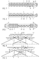
- Fig. 1 is designed as a cross-twist tube with substantially mutually symmetrical to the tube axis X crossing,
- D1, D2 wherein the angle ⁇ to the tube axis X between 67 ° and 72 ° and the resulting twist angle ⁇ to 18 ° to 23 ° perpendicular to the tube axis
- the funneldrallrohr for example similar to that in Fig. 4 shown formed with pointing to the tube interior recesses 3.
- Fig. 1 is the respective inner tube 2 either a smooth tube or also a funneldrallrohr with substantially mutually symmetrical to the tube axis X crossing multi-speed swirls and helix angles ⁇ 1 between 18 ° and 23 °.
- the jacket tube 1 is a smooth tube.
- each inner tube 2 contained in the jacket tube 1 is a Buchdrallrohr with each other substantially symmetrical to the tube axis X intersecting,
- the swirls D1, D2 are more common, so despite the relatively steep angle of attack ⁇ 1 (twist angle ⁇ 1 between 18 ° and 23 °) the entire pipe surface offers the product mainly the heat transfer intensifying macrostructures, and is achieved between the increase in heat transfer and the pressure loss caused by the swirls an optimum.
- Fig. 4 illustrates the macrostructures formed by the intersecting swirls D1, D2 of the respective cross-twist tube as the shell and / or inner tube 1, 2, which are present on the inside and the outside of the tube.
- Fig. 4 lie the tube axis X facing in the axial direction successively trough-like depressions 3, which are each bounded by substantially wedge-shaped ribs 5 and have a twist depth T between 0.8 mm and 1.2 mm.
- the width B of each recess 3 is a multiple of the twist depth T, preferably between 5.0 mm and 20.0 mm.
- a rounded tip 4 is provided corresponding to the recess 3, which is bounded in the axial direction by approximately V-shaped grooves 6.
- Ribs 5 and the grooves 6 be rounded, for example, in terms of a good cleanability of the tube.
- the ribs 5 and the grooves 6 extend as well as the depressions 3 and the studs 4 at the angle of attack ⁇ , ⁇ 1 helical and periodically crossing each other over the entire inner or outer pipe surface.
- FIG. 5 is a funneldrallrohr as a jacket or inner tube 1, 2 indicated, in which the recesses 3 on the outside of the tube (ie the tube axis X facing away) are present.
- the twist depth T is between 0.8 mm and 1.2 mm.
- the helix angles ⁇ , ⁇ 1 are between 18 ° and 23 ° to the tube axis X.
- the in Fig. 5 shown cross-twist tube can be suitably used as the inner tube 2, if, for example, the product between the casing tube, according to Fig. 4 is designed, and the outside of the inner tube 2 flows. If a heat transfer medium is used, which flows in the flow channel between the jacket tube 1 and each inner tube 2, the cross-twist tube of the inner tube 1, 2 is expediently analogous to Fig. 4 educated.
Landscapes
- Engineering & Computer Science (AREA)
- Physics & Mathematics (AREA)
- Thermal Sciences (AREA)
- Mechanical Engineering (AREA)
- General Engineering & Computer Science (AREA)
- Geometry (AREA)
- Heat-Exchange Devices With Radiators And Conduit Assemblies (AREA)
Abstract
Description
- Die Erfindung betrifft einen Röhrenwärmetauscher der im Oberbegriff des Patentanspruchs 1 angegebenen Art sowie ein Innen- und/oder Mantelrohr eines solchen Röhrenwärmetauschers.
- Aus
DE 600 19 635 T2 ist ein Röhrenwärmetauscher zur Behandlung von Säften mit Fasern und/oder Teilchen bekannt, bei dem einfach gedrallte Innen- und/oder Außenrohre verwendet werden. Im Innenrohr ist der Drallwinkel mit etwa 45° dargestellt, während der Drallwinkel im Mantelrohr mit etwa 75°, jeweils bezogen auf die Rohrachse, gezeigt ist. Bei diesem Röhrenwärmetauscher ist es nachteilig, dass zugunsten gesteigerter Wärmeübertragung sehr starker Druckverlust bei gleichbleibender Anströmfläche in Kauf zu nehmen ist und die Grenzschicht der Strömung an den mit dem gleichen Drallwinkel zur Rohrachse verlaufenden Drallungen zu starker Rotation angeregt wird. Dies bedingt sehr hohen, gegebenenfalls für das Produkt nachteiligen, Förderdruck für die Behandlung des Produkts im Röhrenwärmetauscher. - Aus
DE 102 56 232 B4 ist ein Röhrenwärmetauscher zum UHT-Behandeln von Milch und Milchprodukten zur Entkeimung bekannt. Das Mantelrohr ist ein glattes Rohr. Nur die Innenrohre können Kreuzdrallrohre sein, in denen sich die mehrgängigen zueinander gegensinnigen Drallungen unter Anstellwinkeln zwischen 25° und 35° längs zur Rohrachse kreuzen, das heißt mit Drallwinkeln zwischen 65° und 55°. Dieser Winkelbereich ist speziell auf Milch und Milchprodukte abgestimmt, die sehr stark zur Ansatzbildung an der kontaktierten Oberfläche neigen. Deshalb sind die Drallungen zusätzlich elektrochemisch poliert. Die Kombination der beiden Maßnahmen resultiert in einer optimalen Hemmung der Ansatzbildung von Milch und Milchprodukten und somit in langer Standzeit des Röhrenwärmetauschers bis zu einem erforderlichen Reinigungszyklus. Es werden Drallwinkel auch von 45 erwähnt, die hinsichtlich der Wärmeübertragung als optimal anzusehen sind, die jedoch bei Milch und Milchprodukten zu einer unzulässig starken Ansatzbildung führen. Anstellwinkel zwischen 25° und 35° und die zusätzliche Oberflächenbehandlung sind demzufolge für Milch und Milchprodukte hinsichtlich der Hemmung der produktspezifischen Ansatzbildung ein Optimum, bedingen jedoch wie auch die gängigen Drallwinkel von 45 ° zur Rohrachse ein ungünstiges Verhältnis zwischen der erzielten Steigerung des Wärmeübergangs und einer exzessiven Steigerung des Druckverlustes in der Strömung. - Der Erfindung liegt die Aufgabe zugrunde, einen Röhrenwärmetauscher der eingangs genannten Art sowie ein Mantel- und/oder Innenrohr für einen solchen Röhrenwärmetauscher anzugeben, die bei der Bearbeitung von insbesondere Säften oder saftartigen Lebensmittelprodukten mit niedriger, mittlerer oder hoher Viskosität trotz nur moderaten Förderdrucks optimal kurze Verweilzeiten und kleine Wärmetauscherflächen ermöglichen. Dies gilt für alle flüssigen Lebensmittel dieses Viskositätsbereiches.
- Die gestellte Aufgabe wird mit den Merkmalen des Patentanspruchs 1 und des Patentanspruchs 10 gelöst.
- Dank der Verwendung zumindest eines Kreuzdrallrohres in dem Röhrenwärmetauscher (für das Mantelrohr und/oder jedes Innenrohr) wird wegen der sich kreuzenden Drallungen eine erhebliche Steigerung der Wärmeübertragung erzielt. Jedoch wird die erzielbare Steigerung der Wärmeübertragung mit der mit der Kreuzdrallung einhergehenden Steigerung des Druckverlustes bei der Durchströmung durch Beschränken des Anstellwinkels α auf 72° bis 67° längs zur Rohrachse und dem sich daraus ergebenden Drallwinkel von 18° bis 23° senkrecht zur Rohrachse, also auf einen relativ spitzen Winkel, in ein optimales Verhältnis gebracht, das trotz nur moderaten Förderdrucks in einer verkleinerten Wärmetauscherfläche resultiert. In anderen Worten benötigt der Röhrenwärmetauscher aufgrund der Verwendung von solchen Kreuzdrallrohren eine relativ kleine Wärmetauscherfläche und damit kurze Förderstrecke. Die Neigung zur Produktansatzbildung ist bei Säften und saftähnlichen Lebensmittelprodukten von sekundärer Bedeutung, da es bei der Verwendung von Kreuzdrallrohren mit den angegebenen flachen Drallwinkeln primär darauf ankommt, dass Pulpe, Fasern oder Teilchen als Bestandteile der Säfte oder saftartigen Lebensmittelprodukte eben wegen der flachen Drallwinkel nicht zum Verhängen und Sammeln tendieren, sondern zügig weitergespült werden. Ferner wird so eine Reinigung bis zu einem hygienisch einwandfreien Zustand möglich.
- Bei einer zweckmäßigen Ausführungsform weist jede Drallung im Achsschnitt des Rohres eine muldenartige Vertiefung mit beiderseitigen, im Querschnitt annähernd keilförmigen Rippen auf, zwischen denen in der Vertiefung eine Dralltiefe zwischen etwa 0,8 mm bis 1,2 mm vorliegt. Das Zusammenspiel zwischen den relativ flachen Drallwinkeln und der moderaten Dralltiefe resultiert selbst bei moderatem Förderdruck in einem für Säfte und saftartige Lebensmittelprodukte niedriger, mittlerer und hoher Viskositäten optimalem Verhältnis zwischen der Steigerung des Wärmeübergangs und der entstehenden Steigerung des Druckverlustes. Vorzugsweise sind die Vertiefungen und die Rippen an der vom Produkt kontaktierbaren Oberfläche angeordnet.
- Bei einer zweckmäßigen Ausführungsform ist die in Richtung der Rohrachse gesehene Breite in der Vertiefung ein Vielfaches der Dralltiefe. Sie sollte zwischen etwa 5,0 und 20,0 mm liegen. Die Vertiefungen sind relativ weite Mulden, an deren begrenzenden Rippen Bestandteile des Produkts zügig weitergespült werden, und die auch eine hygienisch einwandfreie Reinigung, z.B. für einen Produktwechsel, ermöglichen.
- Um den Effekt der Kreuzdrallung optimal nutzen zu können, bedecken beide mehrgängigen Drallungen die Rohroberfläche vollflächig.
- Bei einer zweckmäßigen Ausführungsform bildet das Mantelrohr als Kreuzdrallrohr mit mehreren Kreuzdrall-Innenrohren einen Modul des Röhrenwärmetauschers. Dieser Modul kann sich zweckmäßiger Weise über 3,0, 6,0 m oder mehr erstrecken und wird, zweckmäßig, zur Behandlung des Produktes im Röhrenwärmetauscher mit mehreren Modulen in Reihe kombiniert.
- Bei einer anderen Ausführungsform sind nur die Innenrohre Kreuzdrallrohre mit den relativ flachen Drallwinkeln, beispielsweise falls im Strömungskanal zwischen dem Mantelrohr und den Innenrohren ein Wärmeträgermedium verwendet wird.
- Bei einer weiteren Ausführungsform weist das Mantelrohr die Vertiefungen der beiden Drallungen an der Rohrinnenseite auf, während das jeweilige Kreuzdrall-Innenrohr die Vertiefungen der Drallungen auf der Außenseite oder der Innenseite aufweist, beispielsweise abhängig davon, entlang welcher Rohroberfläche das Produkt strömt.
- Der Röhrenwärmetauscher ist besonders gut geeignet zur Behandlung von Säften oder saftartigen Lebensmittelprodukten mit Viskositäten > etwa 5 mPas.
- Zur Behandlung des jeweiligen Produktes bieten sich zwei unterschiedliche Verfahren an, entweder ein rekuperatives Verfahren, bei welchem Produkt gegen Produkt getrennt durch das jeweilige Kreuzdrallrohr, z.B. im Gegenstrom, verarbeitet wird, oder ein Verfahren mit einem Wärmeträgermedium gegen das Produkt getrennt durch das jeweilige Kreuzdrallrohr, wobei dann, vorzugsweise, die Vertiefungen der beiden Drallungen des Kreuzdrallrohres dem Produkt zugewandt sind.
- Die verwendeten Kreuzdrallrohre sind zweckmäßig Edelstahlrohre, bei denen die beiden Drallungen an den inneren und äußeren Rohroberflächen in den Strömungen wirksam sind.
- Ausführungsformen des Erfindungsgegenstandes werden anhand der Zeichnungen erläutert. Es zeigen:
- Fig. 1
- einen Röhrenwärmetauscher zur thermischen Behandlung von Säften oder saftartigen Lebensmittelprodukten am Beispiel eines Moduls mit einem Kreuz- drallrohr als Mantelrohr,
- Fig. 2
- eine andere Ausführungsform eines Moduls mit zumindest einem Innenrohr als Kreuzdrallrohr in einem beispielsweise glatten Mantelrohr,
- Fig. 3
- eine weitere Ausführungsform eines Moduls, in welchem das Mantelrohr und jedes Innenrohr als Kreuzdrallrohr ausgebildet sind,
- Fig. 4
- einen Detailschnitt der Rohrwandung eines Kreuzdrallrohres mit zum Rohrin- neren weisenden Vertiefungen der beiden Drallungen, und
- Fig. 5
- einen Querschnitt der Rohrwandung eines Kreuzdrallrohres mit an der Rohr- außenseite liegenden Vertiefungen der beiden Drallungen.
- Ein in
Fig. 1 gezeigter Modul M eines Röhrenwärmetauschers W zur thermischen Behandlung von Säften oder saftartigen Lebensmittelprodukten mit mittleren bis hohen Viskositäten, beispielsweise einer Viskosität von mehr als etwa 5 mPas, besteht aus einem Mantelrohr 1 und zumindest einem im Inneren des Mantelrohres 1 im Abstand von der Innenwand des Mantelrohres 1 untergebrachten, in etwa koaxialen Innenrohr 2. Der Modul M ist in dem Röhrenwärmetauscher W beispielsweise mit nicht gezeigten weiteren, gleichartigen oder ähnlichen Modulen kombiniert, um eine Behandlungsstrecke einer bestimmten Förderlänge zu bilden. Das Produkt wird entweder nach einem rekuperativen Verfahren behandelt, d.h. Produkt gegen Produkt getrennt durch z.B. das Innenrohr 2, oder nach einem Verfahren, bei dem ein Wärmeträgermedium (Dampf oder Wasser) verwendet wird, wobei das Wärmeträgermedium gegen das Produkt getrennt ist durch beispielsweise das jeweilige Innenrohr 2. Das jeweilige Verfahren wird, vorzugsweise, im Gegenstrom oder im Gleichstrom betrieben. Das Mantelrohr 1 inFig. 1 ist als Kreuzdrallrohr mit einander im Wesentlichen symmetrisch zur Rohrachse X kreuzenden, mehrgängigen Drallungen D1, D2 ausgebildet, wobei der Anstellwinkel α zur Rohrachse X zwischen 67° und 72° und dem sich daraus ergebenden Drallwinkels β auf 18° bis 23° senkrecht zur Rohrachse beträgt. Das Kreuzdrallrohr ist beispielsweise ähnlich dem inFig. 4 gezeigten mit zum Rohrinneren weisenden Vertiefungen 3 ausgebildet. InFig. 1 ist das jeweilige Innenrohr 2 entweder ein glattes Rohr oder ebenfalls ein Kreuzdrallrohr mit im Wesentlichen einander symmetrisch zur Rohrachse X kreuzenden mehrgängigen Drallungen und Drallwinkeln β1 zwischen 18° und 23°. - In der Ausführungsform in
Fig. 2 des Moduls M ist das Mantelrohr 1 ein glattes Rohr. Hingegen ist jedes im Mantelrohr 1 enthaltene Innenrohr 2 ein Kreuzdrallrohr mit einander im Wesentlichen symmetrisch zur Rohrachse X kreuzenden, mehrgängigen Drallungen D1, D2 und Anstellwinkeln α1 zwischen 67° und 72°zur Rohrachse X. Die Drallungen D1, D2 sind mehrgängig, damit trotz des relativ steilen Anstellwinkels α1 (Drallwinkel β1 zwischen 18° und 23°) die gesamte Rohroberfläche dem Produkt vor allem den Wärmeübergang intensivierende Makrostrukturen anbietet, und zwischen der Steigerung des Wärmeübergangs und dem durch die Drallungen bedingten Druckverlust ein Optimum erzielt wird. - In der Ausführungsform in
Fig. 3 des Moduls M werden für das Mantelrohr 1 und jedes Innenrohr 2 Kreuzdrallrohre mit einander im Wesentlichen symmetrisch zur Rohrachse X kreuzenden, mehrgängigen Drallungen D1, D2 verwendet, wobei auch hier die Drallwinkel β, β1 zwischen 18° und 23° senkrecht zur Rohrachse X betragen. - Ein Drallwinkel β, β1 von 18° bis 23° zur Rohrachse bedeutet einen Anstellwinkel α, α1 jeder Drallung bezogen auf eine Ebene längs zur Rohrachse X von β, β1 = 90°- Drallwinkel = α, α1 = 67° bis 72°.
-
Fig. 4 verdeutlicht die durch die sich kreuzenden Drallungen D1, D2 des jeweiligen Kreuzdrallrohres als das Mantel- und/oder Innenrohr 1, 2 gebildeten Makrostrukturen, die an der Innenseite und der Außenseite des Rohres vorliegen. InFig. 4 liegen der Rohrachse X zugewandt in Achsrichtung aufeinanderfolgend muldenartige Vertiefungen 3 vor, die jeweils von im Wesentlichen keilförmigen Rippen 5 begrenzt sind und eine Dralltiefe T zwischen 0,8 mm und 1,2 mm haben. Die Breite B jeder Vertiefung 3 beträgt ein Vielfaches der Dralltiefe T, vorzugsweise zwischen 5,0 mm und 20,0 mm. An der Rohraußenseite ist entsprechend der Vertiefung 3 eine gerundete Kuppe 4 vorgesehen, die in axialer Richtung durch annähernd V-förmige Nuten 6 begrenzt wird. Bei einer nicht gezeigten Alternative könnten die Rippen 5 und die Nuten 6 gerundet sein, beispielsweise im Hinblick auf eine gute Reinigbarkeit des Rohres. Die Rippen 5 bzw. die Nuten 6 verlaufen wie auch die Vertiefungen 3 und die Kuppen 4 unter dem Anstellwinkel α, α1 schraubengangartig und periodisch einander kreuzend über die gesamte innere bzw. äußere Rohroberfläche. - In der Ausführungsform in
Fig. 5 ist ein Kreuzdrallrohr als Mantel- oder Innenrohr 1, 2 angedeutet, bei dem die Vertiefungen 3 an der Rohraußenseite (d.h. der Rohrachse X abgewandt) vorliegen. Hierbei weisen die gerundeten Kuppen 4 und die Nuten 6 zur Rohrachse X. Die Dralltiefe T beträgt zwischen 0,8 mm und 1,2 mm. Die Drallwinkel β, β1 liegen zwischen 18° und 23° zur Rohrachse X. Das inFig. 5 gezeigte Kreuzdrallrohr kann zweckmäßig als Innenrohr 2 verwendet werden, falls beispielsweise das Produkt zwischen dem Mantelrohr, das gemäßFig. 4 gestaltet ist, und der Außenseite des Innenrohres 2 strömt. Wird mit einem Wärmeträgermedium gearbeitet, das im Strömungskanal zwischen dem Mantelrohr 1 und jedem Innenrohr 2 strömt, ist zweckmäßig das Kreuzdrallrohr des Innenrohres 1, 2 analog zuFig. 4 ausgebildet. - Aus der Verwendung der Kreuzdrallrohre mit einem Anstellwinkel α, α1 von 67° bis 72° und einer Dralltiefe T zwischen 0,8 mm und 1,2 mm bei einer Drallbreite B zwischen etwa 5,0 mm und 20,0 mm resultiert für mittel- oder höherviskose Säfte oder saftartige Lebensmittelprodukte ein optimales Verhältnis zwischen der durch die Kreuzdralltechnik erzielbaren Steigerung der Wärmeübertragung oder dem Wärmeübertragungskoeffizienten und der in Kauf zu nehmenden Steigerung des Druckverlustes bei der Durchströmung, derart, dass das jeweils angewandte Verfahren (rekuperativ oder mit Wärmeträgermedium) bei nur moderatem Förderdruck eine relativ kleine Wärmetauscherfläche bei dann kurzen Verweilzeiten im Röhrenwärmetauscher erfordert bzw. der Röhrenwärmetauscher W mit einer relativ kurzen Förderstrecke auskommt.
Claims (10)
- Röhrenwärmetauscher (W) zur Behandlung von Säften und saftähnlichen Lebensmittelprodukten mit mittlerer bis hoher Viskosität, mit wenigstens einem zumindest ein Innenrohr (2) enthaltenden Mantelrohr (1), wobei das Innenrohr (2) und/oder das Mantelrohr (1) als Drallrohr mit unter einem Drallwinkel zur Rohrachse (X) schraubengangartig verlaufenden, mehrgängigen Drallungen (D1, D2) ausgebildet ist bzw. sind, dadurch gekennzeichnet, dass als Innen- und/oder Außenrohr (1, 2) ein Kreuzdrallrohr mit sich zumindest im Wesentlichen symmetrisch zur Rohrachse (X) kreuzenden Drallungen (D1, D2) jeweils mit einem Anstellwinkel (α, α1) zwischen 67° und 72° zur Rohrachse (X) und dem daraus resultierenden Drallwinkel (β, β1) von 18° bis 23° senkrecht zur Rohrachse vorgesehen ist.
- Röhrenwärmetauscher nach Anspruch 1, dadurch gekennzeichnet, dass jede Drallung (D1, D2) im Querschnitt eine muldenartige Vertiefung (3) mit beiderseitigen, im Querschnitt annähernd keilförmigen Rippen (5) aufweist, zwischen denen in der Vertiefung (3) eine Dralltiefe (T) zwischen etwa 0,8 mm bis 1,2 mm vorliegt, und dass, vorzugsweise, die Vertiefungen und die Rippen an der vom Produkt kontaktierbaren Oberfläche des Mantelund/oder Innenrohres (1, 2) angeordnet sind.
- Röhrenwärmetauscher nach wenigstens einem der vorhergehenden Ansprüche, dadurch gekennzeichnet, dass die in Richtung der Rohrachse (X) gesehene Breite (B) der Vertiefung (3) ein Vielfaches der Dralltiefe (T) beträgt, vorzugsweise zwischen etwa 5,0 und 20,0 mm.
- Röhrenwärmetauscher nach wenigstens einem der vorhergehenden Ansprüche, dadurch gekennzeichnet, dass beide mehrgängigen Drallungen (D1, D2) die Rohroberfläche vollflächig bedecken.
- Röhrenwärmetauscher nach wenigstens einem der vorhergehenden Ansprüche, dadurch gekennzeichnet, dass das Mantelrohr (1) als Kreuzdrallrohr mehrere Kreuzdrall-Innenrohre (2) enthält und einen Modul (M) des Röhrenwärmetauschers (W) bildet.
- Röhrenwärmetauscher nach wenigstens einem der vorhergehenden Ansprüche, dadurch gekennzeichnet, dass das Mantelrohr (1) die Vertiefungen der Drallungen (D1, D2) an der Rohrinnenseite aufweist, und dass das jeweilige Kreuzdrall-Innenrohr (2) die Vertiefungen der Drallungen (D1, D2) auf der Außenseite oder der Innenseite aufweist.
- Röhrenwärmetauscher nach wenigstens einem der vorhergehenden Ansprüche, dadurch gekennzeichnet, dass in dem Röhrenwärmetauscher (W) Säfte und saftartige Produkte mit Viskositäten > etwa 5 m Pas verarbeitet werden.
- Röhrenwärmetauscher nach wenigstens einem der vorhergehenden Ansprüche, dadurch gekennzeichnet, dass der Saft oder das saftartige Produkt nach einem rekuperativen Verfahren Produkt gegen Produkt getrennt durch das jeweilige Kreuzdrallrohr verarbeitet wird.
- Röhrenwärmetauscher nach wenigstens einem der vorhergehenden Ansprüche, dadurch gekennzeichnet, dass der Saft oder das saftartige Produkt nach einem Verfahren mit einem Wärmeträgermedium gegen das Produkt getrennt durch das jeweilige Kreuzdrallrohr verarbeitet wird, vorzugsweise mit dem Produkt zugewandten Vertiefungen (3).
- Innen- und/oder Mantelrohr (1, 2) eines Röhrenwärmetauschers (W) zur Behandlung von Säften oder saftartigen Lebensmittelprodukten mit einer Viskosität > etwa 5 mPas, dadurch gekennzeichnet, dass als Innen- und/oder Mantelrohr (1, 2) ein Kreuzdrallrohr mit sich zumindest weitgehend symmetrisch zur Rohrachse (X) kreuzenden mehrgängigen Drallungen (D1, D2) verwendet wird, und dass die Anstellwinkel (α, α1) zur Rohrachse (X) zwischen 67° und 72° und die Dralltiefe (T) in von den Drallungen (D1, D2) gebildeten Vertiefungen (3) zwischen etwa 0,8 mm bis 1,2 mm betragen.
Priority Applications (1)
| Application Number | Priority Date | Filing Date | Title |
|---|---|---|---|
| PL10171888T PL2299227T3 (pl) | 2009-09-08 | 2010-08-04 | Rurowy wymiennik ciepła |
Applications Claiming Priority (1)
| Application Number | Priority Date | Filing Date | Title |
|---|---|---|---|
| DE102009040558A DE102009040558A1 (de) | 2009-09-08 | 2009-09-08 | Röhrenwärmetauscher |
Publications (3)
| Publication Number | Publication Date |
|---|---|
| EP2299227A2 true EP2299227A2 (de) | 2011-03-23 |
| EP2299227A3 EP2299227A3 (de) | 2016-12-07 |
| EP2299227B1 EP2299227B1 (de) | 2018-09-19 |
Family
ID=43242416
Family Applications (1)
| Application Number | Title | Priority Date | Filing Date |
|---|---|---|---|
| EP10171888.0A Active EP2299227B1 (de) | 2009-09-08 | 2010-08-04 | Röhrenwärmetauscher |
Country Status (8)
| Country | Link |
|---|---|
| US (1) | US20110056663A1 (de) |
| EP (1) | EP2299227B1 (de) |
| CN (1) | CN102012177A (de) |
| BR (1) | BRPI1003318A2 (de) |
| DE (1) | DE102009040558A1 (de) |
| ES (1) | ES2691257T3 (de) |
| HU (1) | HUE041374T2 (de) |
| PL (1) | PL2299227T3 (de) |
Families Citing this family (5)
| Publication number | Priority date | Publication date | Assignee | Title |
|---|---|---|---|---|
| DE102011006653A1 (de) | 2011-04-01 | 2012-10-04 | Krones Aktiengesellschaft | Getränkeerhitzungssystem mit integrierter Verbrennungsanlage und Verfahren zum Erhitzen von Getränken |
| RU2548332C1 (ru) * | 2013-10-08 | 2015-04-20 | Николай Григорьевич Гладков | Теплообменник |
| CN104713405B (zh) * | 2015-03-04 | 2016-08-17 | 东南大学 | 一种正三角形排列的对涡排阵列换热装置 |
| RU2622340C1 (ru) * | 2016-07-15 | 2017-06-14 | Федеральное государственное бюджетное образовательное учреждение высшего образования "Юго-Западный государственный университет" (ЮЗГУ) | Вихревой теплообменный элемент |
| RU2672229C1 (ru) * | 2017-10-17 | 2018-11-12 | Федеральное государственное бюджетное образовательное учреждение высшего образования " Юго-Западный государственный университет" (ЮЗГУ) | Вихревой теплообменный элемент |
Citations (2)
| Publication number | Priority date | Publication date | Assignee | Title |
|---|---|---|---|---|
| DE10256232B4 (de) | 2002-12-02 | 2004-10-21 | Tuchenhagen Dairy Systems Gmbh | Vorrichtung zur Verlängerung der Standzeit von Rohrbündel-Wärmeaustauschern in indirekt beheizten UHT-Anlagen für Nahrungsmittel |
| DE60019635T2 (de) | 1999-10-26 | 2006-03-02 | Tetra Laval Holdings & Finance S.A. | Rohrwärmetauscher-anordnung |
Family Cites Families (20)
| Publication number | Priority date | Publication date | Assignee | Title |
|---|---|---|---|---|
| US1426515A (en) * | 1919-06-14 | 1922-08-22 | Harry M Sprecher | Milk-cooling apparatus |
| US1797014A (en) * | 1923-11-12 | 1931-03-17 | Edgar B Nichols | Milk-treatment tank |
| US1918966A (en) * | 1930-06-20 | 1933-07-18 | Gen Chemical Corp | Apparatus for treating gas |
| US2080537A (en) * | 1935-12-06 | 1937-05-18 | Cherry Burrell Corp | Processing vat |
| US2353912A (en) * | 1940-04-23 | 1944-07-18 | Elmer H Berryman | Means for homogenizing and heat-treating fluids |
| US2413360A (en) * | 1940-10-02 | 1946-12-31 | Walter Maguire Company Inc | Heat exchanger |
| US2589262A (en) * | 1946-06-12 | 1952-03-18 | Hydrocarbon Research Inc | Heat exchanger |
| DE1539323A1 (de) * | 1966-06-08 | 1969-10-02 | Siemens Ag | Thermogenerator |
| US3850231A (en) * | 1973-05-24 | 1974-11-26 | Combustion Eng | Lmfbr intermediate heat exchanger |
| DE9403913U1 (de) * | 1994-03-09 | 1994-05-05 | Gea Finnah Gmbh | Rohrbündel-Wärmetauscher |
| US6250379B1 (en) * | 1994-05-17 | 2001-06-26 | Hde Metallwerk Gmbh | High-speed capillary tube heat exchanger |
| US5992512A (en) * | 1996-03-21 | 1999-11-30 | The Furukawa Electric Co., Ltd. | Heat exchanger tube and method for manufacturing the same |
| US6273180B1 (en) * | 1998-12-23 | 2001-08-14 | L'air Liquide, Societe Anonyme Pour L'etude Et L'eploitation Des Procedes Georges Claude | Heat exchanger for preheating an oxidizing gas |
| DE10156374C1 (de) * | 2001-11-16 | 2003-02-27 | Wieland Werke Ag | Beidseitig strukturiertes Wärmeaustauscherrohr und Verfahren zu dessen Herstellung |
| DE10210016B9 (de) * | 2002-03-07 | 2004-09-09 | Wieland-Werke Ag | Wärmeaustauschrohr mit berippter Innenoberfläche |
| CN2630783Y (zh) * | 2003-02-17 | 2004-08-04 | 董斌 | 多向扰流强化换热管 |
| US20040244958A1 (en) * | 2003-06-04 | 2004-12-09 | Roland Dilley | Multi-spiral upset heat exchanger tube |
| CN100451531C (zh) * | 2005-03-25 | 2009-01-14 | 清华大学 | 一种热水器换热管 |
| CN100489436C (zh) * | 2006-07-07 | 2009-05-20 | 北京美联桥科技发展有限公司 | 一种应用交叉螺旋管的换热器 |
| DE102008001659B4 (de) * | 2007-07-11 | 2014-01-30 | Halla Visteon Climate Control Corp. | Abgaswärmetauscher mit integrierter Montageschnittstelle |
-
2009
- 2009-09-08 DE DE102009040558A patent/DE102009040558A1/de not_active Ceased
-
2010
- 2010-08-04 HU HUE10171888A patent/HUE041374T2/hu unknown
- 2010-08-04 EP EP10171888.0A patent/EP2299227B1/de active Active
- 2010-08-04 ES ES10171888.0T patent/ES2691257T3/es active Active
- 2010-08-04 PL PL10171888T patent/PL2299227T3/pl unknown
- 2010-09-03 US US12/875,348 patent/US20110056663A1/en not_active Abandoned
- 2010-09-06 BR BRPI1003318-1A patent/BRPI1003318A2/pt not_active IP Right Cessation
- 2010-09-07 CN CN201010277173XA patent/CN102012177A/zh active Pending
Patent Citations (2)
| Publication number | Priority date | Publication date | Assignee | Title |
|---|---|---|---|---|
| DE60019635T2 (de) | 1999-10-26 | 2006-03-02 | Tetra Laval Holdings & Finance S.A. | Rohrwärmetauscher-anordnung |
| DE10256232B4 (de) | 2002-12-02 | 2004-10-21 | Tuchenhagen Dairy Systems Gmbh | Vorrichtung zur Verlängerung der Standzeit von Rohrbündel-Wärmeaustauschern in indirekt beheizten UHT-Anlagen für Nahrungsmittel |
Also Published As
| Publication number | Publication date |
|---|---|
| BRPI1003318A2 (pt) | 2012-05-29 |
| CN102012177A (zh) | 2011-04-13 |
| DE102009040558A1 (de) | 2011-03-10 |
| US20110056663A1 (en) | 2011-03-10 |
| EP2299227A3 (de) | 2016-12-07 |
| ES2691257T3 (es) | 2018-11-26 |
| HUE041374T2 (hu) | 2019-05-28 |
| EP2299227B1 (de) | 2018-09-19 |
| PL2299227T3 (pl) | 2019-06-28 |
Similar Documents
| Publication | Publication Date | Title |
|---|---|---|
| EP2299227B1 (de) | Röhrenwärmetauscher | |
| DE69412500T2 (de) | Uv-gerät zur behandlung einer flüssigkeit | |
| WO2010017864A1 (de) | Verfahren und vorrichtung zur wärmebehandlung von flüssigen lebensmitteln | |
| DE102013222059A1 (de) | Wärmeübertragungsrohr und Cracking-Ofen, der das Wärmeübertragungsrohr verwendet | |
| DE69313804T2 (de) | Statische Mischvorrichtung | |
| EP2812581B1 (de) | Pumpe mit integrierter heizung | |
| EP0838190A2 (de) | Durchlaufgeschirrspülvorrichtung sowie Verfahren zum Reinigen von Geschirr- und/oder Tabletteilen | |
| DE10256232B4 (de) | Vorrichtung zur Verlängerung der Standzeit von Rohrbündel-Wärmeaustauschern in indirekt beheizten UHT-Anlagen für Nahrungsmittel | |
| DE10333477A1 (de) | Strömungskanal für Flüssigkeiten | |
| EP3215277A1 (de) | Holzauftauanlage | |
| DE19944552B4 (de) | Vorrichtung zum Kochen von Eiern | |
| EP0878136B1 (de) | Vorrichtung zur Flüssigkeitsbeaufschlagung von Gefässen | |
| DE102005055016B4 (de) | Verfahren und Röhren-Wärmeaustauscher zur thermischen Behandlung hochviskoser Produkte der Nahrungsmittel- und Getränkeindustrie | |
| DE1542151C3 (de) | Wischer für Dünnschichtreaktions- oder -verdampf errohr | |
| EP3485169B1 (de) | Verfahren und anlage zur behandlung hitzeempfindlicher flüssiger nahrungsmittelprodukte und zentrifugalpumpe für eine solche anlage | |
| DE102012106748A1 (de) | Vollmantel-Schneckenzentrifuge | |
| WO2004042314A1 (de) | System zum reinigen von rohren von wärmetauschern | |
| WO2015113750A1 (de) | Verfahren und uht-anlage zur herstellung einer trinkfähigen mischung aus einer trägerflüssigkeit und wenigstens einer zerealie unter aseptischen bedingungen | |
| DE202009011215U1 (de) | Wasserwirbler | |
| DE29716644U1 (de) | Vorrichtung zur Flüssigkeitsbeaufschlagung von Gefäßen | |
| DE1985743U (de) | Vorrichtung zum stufenweisen entziehen eliminierbarer bestandteile aus vornehmlich aus kunststoff bestehendem foerdergut. | |
| DE3106875A1 (de) | Waermetauscher zur aufheizung von maische oder bierwuerze | |
| EP0056611A2 (de) | Liegender Behälter, insbesondere zur Behandlung von Weinmaische | |
| EP2494873B1 (de) | Reinigungsvorrichtung für eine Temperiermaschine | |
| EP2261587A1 (de) | Anlage zur Trocknung von Klärschlamm |
Legal Events
| Date | Code | Title | Description |
|---|---|---|---|
| PUAI | Public reference made under article 153(3) epc to a published international application that has entered the european phase |
Free format text: ORIGINAL CODE: 0009012 |
|
| AK | Designated contracting states |
Kind code of ref document: A2 Designated state(s): AL AT BE BG CH CY CZ DE DK EE ES FI FR GB GR HR HU IE IS IT LI LT LU LV MC MK MT NL NO PL PT RO SE SI SK SM TR |
|
| AX | Request for extension of the european patent |
Extension state: BA ME RS |
|
| RIN1 | Information on inventor provided before grant (corrected) |
Inventor name: ZACHARIAS, JOERG Inventor name: FEILNER, ROLAND |
|
| PUAL | Search report despatched |
Free format text: ORIGINAL CODE: 0009013 |
|
| AK | Designated contracting states |
Kind code of ref document: A3 Designated state(s): AL AT BE BG CH CY CZ DE DK EE ES FI FR GB GR HR HU IE IS IT LI LT LU LV MC MK MT NL NO PL PT RO SE SI SK SM TR |
|
| AX | Request for extension of the european patent |
Extension state: BA ME RS |
|
| RIC1 | Information provided on ipc code assigned before grant |
Ipc: F28D 7/10 20060101AFI20161103BHEP Ipc: F28F 1/42 20060101ALI20161103BHEP Ipc: F28F 1/40 20060101ALI20161103BHEP Ipc: F28F 1/36 20060101ALI20161103BHEP Ipc: F28F 13/12 20060101ALI20161103BHEP |
|
| STAA | Information on the status of an ep patent application or granted ep patent |
Free format text: STATUS: REQUEST FOR EXAMINATION WAS MADE |
|
| 17P | Request for examination filed |
Effective date: 20170526 |
|
| RBV | Designated contracting states (corrected) |
Designated state(s): AL AT BE BG CH CY CZ DE DK EE ES FI FR GB GR HR HU IE IS IT LI LT LU LV MC MK MT NL NO PL PT RO SE SI SK SM TR |
|
| STAA | Information on the status of an ep patent application or granted ep patent |
Free format text: STATUS: EXAMINATION IS IN PROGRESS |
|
| 17Q | First examination report despatched |
Effective date: 20171018 |
|
| GRAP | Despatch of communication of intention to grant a patent |
Free format text: ORIGINAL CODE: EPIDOSNIGR1 |
|
| STAA | Information on the status of an ep patent application or granted ep patent |
Free format text: STATUS: GRANT OF PATENT IS INTENDED |
|
| INTG | Intention to grant announced |
Effective date: 20180305 |
|
| GRAS | Grant fee paid |
Free format text: ORIGINAL CODE: EPIDOSNIGR3 |
|
| GRAA | (expected) grant |
Free format text: ORIGINAL CODE: 0009210 |
|
| STAA | Information on the status of an ep patent application or granted ep patent |
Free format text: STATUS: THE PATENT HAS BEEN GRANTED |
|
| AK | Designated contracting states |
Kind code of ref document: B1 Designated state(s): AL AT BE BG CH CY CZ DE DK EE ES FI FR GB GR HR HU IE IS IT LI LT LU LV MC MK MT NL NO PL PT RO SE SI SK SM TR |
|
| REG | Reference to a national code |
Ref country code: GB Ref legal event code: FG4D Free format text: NOT ENGLISH |
|
| REG | Reference to a national code |
Ref country code: CH Ref legal event code: EP |
|
| REG | Reference to a national code |
Ref country code: AT Ref legal event code: REF Ref document number: 1043736 Country of ref document: AT Kind code of ref document: T Effective date: 20181015 |
|
| REG | Reference to a national code |
Ref country code: IE Ref legal event code: FG4D Free format text: LANGUAGE OF EP DOCUMENT: GERMAN |
|
| REG | Reference to a national code |
Ref country code: DE Ref legal event code: R096 Ref document number: 502010015379 Country of ref document: DE |
|
| REG | Reference to a national code |
Ref country code: ES Ref legal event code: FG2A Ref document number: 2691257 Country of ref document: ES Kind code of ref document: T3 Effective date: 20181126 |
|
| REG | Reference to a national code |
Ref country code: NL Ref legal event code: MP Effective date: 20180919 |
|
| REG | Reference to a national code |
Ref country code: SE Ref legal event code: TRGR |
|
| PG25 | Lapsed in a contracting state [announced via postgrant information from national office to epo] |
Ref country code: GR Free format text: LAPSE BECAUSE OF FAILURE TO SUBMIT A TRANSLATION OF THE DESCRIPTION OR TO PAY THE FEE WITHIN THE PRESCRIBED TIME-LIMIT Effective date: 20181220 Ref country code: LT Free format text: LAPSE BECAUSE OF FAILURE TO SUBMIT A TRANSLATION OF THE DESCRIPTION OR TO PAY THE FEE WITHIN THE PRESCRIBED TIME-LIMIT Effective date: 20180919 Ref country code: FI Free format text: LAPSE BECAUSE OF FAILURE TO SUBMIT A TRANSLATION OF THE DESCRIPTION OR TO PAY THE FEE WITHIN THE PRESCRIBED TIME-LIMIT Effective date: 20180919 Ref country code: BG Free format text: LAPSE BECAUSE OF FAILURE TO SUBMIT A TRANSLATION OF THE DESCRIPTION OR TO PAY THE FEE WITHIN THE PRESCRIBED TIME-LIMIT Effective date: 20181219 Ref country code: NO Free format text: LAPSE BECAUSE OF FAILURE TO SUBMIT A TRANSLATION OF THE DESCRIPTION OR TO PAY THE FEE WITHIN THE PRESCRIBED TIME-LIMIT Effective date: 20181219 |
|
| REG | Reference to a national code |
Ref country code: LT Ref legal event code: MG4D |
|
| PG25 | Lapsed in a contracting state [announced via postgrant information from national office to epo] |
Ref country code: HR Free format text: LAPSE BECAUSE OF FAILURE TO SUBMIT A TRANSLATION OF THE DESCRIPTION OR TO PAY THE FEE WITHIN THE PRESCRIBED TIME-LIMIT Effective date: 20180919 Ref country code: LV Free format text: LAPSE BECAUSE OF FAILURE TO SUBMIT A TRANSLATION OF THE DESCRIPTION OR TO PAY THE FEE WITHIN THE PRESCRIBED TIME-LIMIT Effective date: 20180919 Ref country code: AL Free format text: LAPSE BECAUSE OF FAILURE TO SUBMIT A TRANSLATION OF THE DESCRIPTION OR TO PAY THE FEE WITHIN THE PRESCRIBED TIME-LIMIT Effective date: 20180919 |
|
| PG25 | Lapsed in a contracting state [announced via postgrant information from national office to epo] |
Ref country code: RO Free format text: LAPSE BECAUSE OF FAILURE TO SUBMIT A TRANSLATION OF THE DESCRIPTION OR TO PAY THE FEE WITHIN THE PRESCRIBED TIME-LIMIT Effective date: 20180919 Ref country code: CZ Free format text: LAPSE BECAUSE OF FAILURE TO SUBMIT A TRANSLATION OF THE DESCRIPTION OR TO PAY THE FEE WITHIN THE PRESCRIBED TIME-LIMIT Effective date: 20180919 Ref country code: EE Free format text: LAPSE BECAUSE OF FAILURE TO SUBMIT A TRANSLATION OF THE DESCRIPTION OR TO PAY THE FEE WITHIN THE PRESCRIBED TIME-LIMIT Effective date: 20180919 Ref country code: NL Free format text: LAPSE BECAUSE OF FAILURE TO SUBMIT A TRANSLATION OF THE DESCRIPTION OR TO PAY THE FEE WITHIN THE PRESCRIBED TIME-LIMIT Effective date: 20180919 Ref country code: IS Free format text: LAPSE BECAUSE OF FAILURE TO SUBMIT A TRANSLATION OF THE DESCRIPTION OR TO PAY THE FEE WITHIN THE PRESCRIBED TIME-LIMIT Effective date: 20190119 |
|
| REG | Reference to a national code |
Ref country code: HU Ref legal event code: AG4A Ref document number: E041374 Country of ref document: HU |
|
| PG25 | Lapsed in a contracting state [announced via postgrant information from national office to epo] |
Ref country code: PT Free format text: LAPSE BECAUSE OF FAILURE TO SUBMIT A TRANSLATION OF THE DESCRIPTION OR TO PAY THE FEE WITHIN THE PRESCRIBED TIME-LIMIT Effective date: 20190119 Ref country code: SK Free format text: LAPSE BECAUSE OF FAILURE TO SUBMIT A TRANSLATION OF THE DESCRIPTION OR TO PAY THE FEE WITHIN THE PRESCRIBED TIME-LIMIT Effective date: 20180919 Ref country code: SM Free format text: LAPSE BECAUSE OF FAILURE TO SUBMIT A TRANSLATION OF THE DESCRIPTION OR TO PAY THE FEE WITHIN THE PRESCRIBED TIME-LIMIT Effective date: 20180919 |
|
| REG | Reference to a national code |
Ref country code: DE Ref legal event code: R097 Ref document number: 502010015379 Country of ref document: DE |
|
| PLBE | No opposition filed within time limit |
Free format text: ORIGINAL CODE: 0009261 |
|
| STAA | Information on the status of an ep patent application or granted ep patent |
Free format text: STATUS: NO OPPOSITION FILED WITHIN TIME LIMIT |
|
| PG25 | Lapsed in a contracting state [announced via postgrant information from national office to epo] |
Ref country code: DK Free format text: LAPSE BECAUSE OF FAILURE TO SUBMIT A TRANSLATION OF THE DESCRIPTION OR TO PAY THE FEE WITHIN THE PRESCRIBED TIME-LIMIT Effective date: 20180919 |
|
| 26N | No opposition filed |
Effective date: 20190620 |
|
| PG25 | Lapsed in a contracting state [announced via postgrant information from national office to epo] |
Ref country code: SI Free format text: LAPSE BECAUSE OF FAILURE TO SUBMIT A TRANSLATION OF THE DESCRIPTION OR TO PAY THE FEE WITHIN THE PRESCRIBED TIME-LIMIT Effective date: 20180919 |
|
| PGFP | Annual fee paid to national office [announced via postgrant information from national office to epo] |
Ref country code: HU Payment date: 20190718 Year of fee payment: 10 |
|
| PG25 | Lapsed in a contracting state [announced via postgrant information from national office to epo] |
Ref country code: TR Free format text: LAPSE BECAUSE OF FAILURE TO SUBMIT A TRANSLATION OF THE DESCRIPTION OR TO PAY THE FEE WITHIN THE PRESCRIBED TIME-LIMIT Effective date: 20180919 |
|
| PG25 | Lapsed in a contracting state [announced via postgrant information from national office to epo] |
Ref country code: LI Free format text: LAPSE BECAUSE OF NON-PAYMENT OF DUE FEES Effective date: 20190831 Ref country code: LU Free format text: LAPSE BECAUSE OF NON-PAYMENT OF DUE FEES Effective date: 20190804 Ref country code: MC Free format text: LAPSE BECAUSE OF FAILURE TO SUBMIT A TRANSLATION OF THE DESCRIPTION OR TO PAY THE FEE WITHIN THE PRESCRIBED TIME-LIMIT Effective date: 20180919 Ref country code: CH Free format text: LAPSE BECAUSE OF NON-PAYMENT OF DUE FEES Effective date: 20190831 |
|
| REG | Reference to a national code |
Ref country code: BE Ref legal event code: MM Effective date: 20190831 |
|
| PG25 | Lapsed in a contracting state [announced via postgrant information from national office to epo] |
Ref country code: IE Free format text: LAPSE BECAUSE OF NON-PAYMENT OF DUE FEES Effective date: 20190804 Ref country code: FR Free format text: LAPSE BECAUSE OF NON-PAYMENT OF DUE FEES Effective date: 20190831 |
|
| PG25 | Lapsed in a contracting state [announced via postgrant information from national office to epo] |
Ref country code: BE Free format text: LAPSE BECAUSE OF NON-PAYMENT OF DUE FEES Effective date: 20190831 |
|
| REG | Reference to a national code |
Ref country code: AT Ref legal event code: MM01 Ref document number: 1043736 Country of ref document: AT Kind code of ref document: T Effective date: 20190804 |
|
| PGFP | Annual fee paid to national office [announced via postgrant information from national office to epo] |
Ref country code: GB Payment date: 20200722 Year of fee payment: 11 Ref country code: ES Payment date: 20200901 Year of fee payment: 11 |
|
| PG25 | Lapsed in a contracting state [announced via postgrant information from national office to epo] |
Ref country code: AT Free format text: LAPSE BECAUSE OF NON-PAYMENT OF DUE FEES Effective date: 20190804 |
|
| PGFP | Annual fee paid to national office [announced via postgrant information from national office to epo] |
Ref country code: IT Payment date: 20200713 Year of fee payment: 11 Ref country code: PL Payment date: 20200717 Year of fee payment: 11 Ref country code: SE Payment date: 20200811 Year of fee payment: 11 |
|
| PG25 | Lapsed in a contracting state [announced via postgrant information from national office to epo] |
Ref country code: HU Free format text: LAPSE BECAUSE OF NON-PAYMENT OF DUE FEES Effective date: 20200805 |
|
| PG25 | Lapsed in a contracting state [announced via postgrant information from national office to epo] |
Ref country code: CY Free format text: LAPSE BECAUSE OF FAILURE TO SUBMIT A TRANSLATION OF THE DESCRIPTION OR TO PAY THE FEE WITHIN THE PRESCRIBED TIME-LIMIT Effective date: 20180919 |
|
| PG25 | Lapsed in a contracting state [announced via postgrant information from national office to epo] |
Ref country code: MT Free format text: LAPSE BECAUSE OF FAILURE TO SUBMIT A TRANSLATION OF THE DESCRIPTION OR TO PAY THE FEE WITHIN THE PRESCRIBED TIME-LIMIT Effective date: 20180919 |
|
| REG | Reference to a national code |
Ref country code: SE Ref legal event code: EUG |
|
| GBPC | Gb: european patent ceased through non-payment of renewal fee |
Effective date: 20210804 |
|
| PG25 | Lapsed in a contracting state [announced via postgrant information from national office to epo] |
Ref country code: SE Free format text: LAPSE BECAUSE OF NON-PAYMENT OF DUE FEES Effective date: 20210805 |
|
| PG25 | Lapsed in a contracting state [announced via postgrant information from national office to epo] |
Ref country code: MK Free format text: LAPSE BECAUSE OF FAILURE TO SUBMIT A TRANSLATION OF THE DESCRIPTION OR TO PAY THE FEE WITHIN THE PRESCRIBED TIME-LIMIT Effective date: 20180919 |
|
| PG25 | Lapsed in a contracting state [announced via postgrant information from national office to epo] |
Ref country code: IT Free format text: LAPSE BECAUSE OF NON-PAYMENT OF DUE FEES Effective date: 20210804 Ref country code: GB Free format text: LAPSE BECAUSE OF NON-PAYMENT OF DUE FEES Effective date: 20210804 |
|
| REG | Reference to a national code |
Ref country code: ES Ref legal event code: FD2A Effective date: 20221003 |
|
| PG25 | Lapsed in a contracting state [announced via postgrant information from national office to epo] |
Ref country code: ES Free format text: LAPSE BECAUSE OF NON-PAYMENT OF DUE FEES Effective date: 20210805 |
|
| P01 | Opt-out of the competence of the unified patent court (upc) registered |
Effective date: 20230523 |
|
| PG25 | Lapsed in a contracting state [announced via postgrant information from national office to epo] |
Ref country code: PL Free format text: LAPSE BECAUSE OF NON-PAYMENT OF DUE FEES Effective date: 20210804 |
|
| PGFP | Annual fee paid to national office [announced via postgrant information from national office to epo] |
Ref country code: DE Payment date: 20250702 Year of fee payment: 16 |