EP2299228B1 - Vorrichtung und Verfahren zum Ausgleichen der Temperatur der Austrittsflächenplatte warmer Flüssigkeiten in Wärmetauschern - Google Patents
Vorrichtung und Verfahren zum Ausgleichen der Temperatur der Austrittsflächenplatte warmer Flüssigkeiten in Wärmetauschern Download PDFInfo
- Publication number
- EP2299228B1 EP2299228B1 EP10173358.2A EP10173358A EP2299228B1 EP 2299228 B1 EP2299228 B1 EP 2299228B1 EP 10173358 A EP10173358 A EP 10173358A EP 2299228 B1 EP2299228 B1 EP 2299228B1
- Authority
- EP
- European Patent Office
- Prior art keywords
- plate
- fluid
- flow
- region
- variable flow
- Prior art date
- Legal status (The legal status is an assumption and is not a legal conclusion. Google has not performed a legal analysis and makes no representation as to the accuracy of the status listed.)
- Active
Links
Images




Classifications
-
- F—MECHANICAL ENGINEERING; LIGHTING; HEATING; WEAPONS; BLASTING
- F28—HEAT EXCHANGE IN GENERAL
- F28F—DETAILS OF HEAT-EXCHANGE AND HEAT-TRANSFER APPARATUS, OF GENERAL APPLICATION
- F28F3/00—Plate-like or laminated elements; Assemblies of plate-like or laminated elements
- F28F3/02—Elements or assemblies thereof with means for increasing heat-transfer area, e.g. with fins, with recesses, with corrugations
- F28F3/04—Elements or assemblies thereof with means for increasing heat-transfer area, e.g. with fins, with recesses, with corrugations the means being integral with the element
- F28F3/042—Elements or assemblies thereof with means for increasing heat-transfer area, e.g. with fins, with recesses, with corrugations the means being integral with the element in the form of local deformations of the element
- F28F3/044—Elements or assemblies thereof with means for increasing heat-transfer area, e.g. with fins, with recesses, with corrugations the means being integral with the element in the form of local deformations of the element the deformations being pontual, e.g. dimples
-
- F—MECHANICAL ENGINEERING; LIGHTING; HEATING; WEAPONS; BLASTING
- F28—HEAT EXCHANGE IN GENERAL
- F28D—HEAT-EXCHANGE APPARATUS, NOT PROVIDED FOR IN ANOTHER SUBCLASS, IN WHICH THE HEAT-EXCHANGE MEDIA DO NOT COME INTO DIRECT CONTACT
- F28D9/00—Heat-exchange apparatus having stationary plate-like or laminated conduit assemblies for both heat-exchange media, the media being in contact with different sides of a conduit wall
-
- F—MECHANICAL ENGINEERING; LIGHTING; HEATING; WEAPONS; BLASTING
- F28—HEAT EXCHANGE IN GENERAL
- F28F—DETAILS OF HEAT-EXCHANGE AND HEAT-TRANSFER APPARATUS, OF GENERAL APPLICATION
- F28F13/00—Arrangements for modifying heat-transfer, e.g. increasing, decreasing
- F28F13/06—Arrangements for modifying heat-transfer, e.g. increasing, decreasing by affecting the pattern of flow of the heat-exchange media
- F28F13/08—Arrangements for modifying heat-transfer, e.g. increasing, decreasing by affecting the pattern of flow of the heat-exchange media by varying the cross-section of the flow channels
-
- Y—GENERAL TAGGING OF NEW TECHNOLOGICAL DEVELOPMENTS; GENERAL TAGGING OF CROSS-SECTIONAL TECHNOLOGIES SPANNING OVER SEVERAL SECTIONS OF THE IPC; TECHNICAL SUBJECTS COVERED BY FORMER USPC CROSS-REFERENCE ART COLLECTIONS [XRACs] AND DIGESTS
- Y10—TECHNICAL SUBJECTS COVERED BY FORMER USPC
- Y10T—TECHNICAL SUBJECTS COVERED BY FORMER US CLASSIFICATION
- Y10T29/00—Metal working
- Y10T29/49—Method of mechanical manufacture
- Y10T29/4935—Heat exchanger or boiler making
Definitions
- Exemplary embodiments of an apparatus and method for equalizing hot fluid exit plane plate temperatures relate to plate-type fluid-to-fluid heat exchangers. More specifically, the embodiments relate to heat exchangers constructed to minimize deleterious effects attributable to cold spots on plates that form a heat exchanger matrix.
- a fluid-to-fluid heat exchanger matrix is designed to extract energy from, for example, hot exhaust gas.
- a cooler opposing gas stream draws thermal energy from the hot gas stream across intervening plates and cools the hot gas stream.
- the temperature of the hot gas is low as it comes into contact with a metal surface of a plate that separates incoming cooler gas from the exiting cooled hot gas.
- the plate temperature may be low due to close proximity to the cool gas entry plane.
- a dew point temperature of hot gas constituents may be reached, and condensation may occur.
- corrosive constituents are present in the gas streams, corrosive condensation or fouling due to particulate accumulation may cause premature failure of the heat exchanger matrix.
- An ideal fluid-to-fluid heat exchanger (hereinafter a gas-to-gas heat exchanger by way of example only) should cool hot process gas to a temperature that merely approaches the dew point temperature of corrosive constituents so that the hot gas exits the heat exchanger matrix without first condensing the constituents on a cold spot near the hot gas exit plane, or any portion of a plate of the heat exchanger matrix.
- Heat exchangers generally do not accommodate true counterflow of hot and cool gas streams and therefore hot process gas, at a plane perpendicular to gas flow, does not cool evenly as it progresses through and exits the heat exchanger matrix. Thus, cold spots may form on plates of the heat exchanger matrix.
- gas-to-gas heat exchangers used today are of a crossflow or quasi-counter-flow design. Unless special design procedures are used, heat exchanger matrix plate temperatures near the hot gas exit plane (and cold gas exit plane) may exhibit temperatures lower than other points on the plates.
- heat exchanger matrix plate temperatures near the hot gas exit plane and cold gas exit plane
- thermally insulate part of the heat exchanger plates Insulation technology may be used to increase the metal plate temperature in a cold corner of the plate at the hot gas exit plane, resulting in condensation-free operation.
- this technique may result in added costs and wasted heat exchanger surface area.
- US-A-2005/0056412 discloses a fluid to fluid heat exchanger having the features in the preamble of claim 1 and describes a fuel vaporizer that alternates fuel/water flow path defining cells and hot gas flow path cells by providing heat transfer augmentation, such as a lanced and offset fin, only in that part of the gas flow path structure adjacent the regions in the fuel/water flow path cells where heating of the liquid fuel/water and vaporizing of the fuel/water where the mixture exists is a two phase material occurs and not in the area adjacent those parts of the fuel/water flow path structure in which superheating of the vaporized fuel/water mixture is occurring.
- heat transfer augmentation such as a lanced and offset fin
- EP-A-1022533 discloses a fluid to fluid heat exchanger having the features in the preamble of claim 1 and discloses a heat exchanger in which the ends of heat transfer plates are formed by bending folding plate blanks in a zigzag fashion along folding lines, are cut in an angle shape, and flange portions formed by folding apexes of the angle shape are superimposed one on another and brazed in a surface contact state, thereby to form combustion gas passage inlets and air passage outlets along the two end edges of the angle shapes.
- heat exchangers are disclosed in DE-A-10033965 , EP-A-1715278 , US-A-5172759 and US-A-2005/274501 .
- a fluid-to-fluid heat exchanger matrix comprises:
- Hot gas (represented by arrows 140) enters at the top of the matrix at a temperature T3 of, for example, 1000°F, and exits at the bottom of the matrix.
- Cooling gas enters the matrix at a cool gas entry plane 175 on a side of the matrix adjacent to its bottom (represented by arrow T1) and exits the matrix on a side of the matrix adjacent to its top (represented by arrow T2).
- T1 a temperature of the matrix adjacent to its bottom
- T2 exits the matrix on a side of the matrix adjacent to its top
- T2 a varying temperature distribution exists due to leaving hot gas 150 (cooled hot gas).
- the temperature of the leaving hot gas is lowest, 450°F.
- the temperature of the leaving hot gas 150 increases by about 100°F, respectively.
- the temperature of the leaving hot gas 150 is 800°F. While the average temperature of leaving hot gas 150 is 650°F, the deviation among temperatures of leaving hot gas 150 at plate points 150a-150d is significant.
- Plate point 150a the point at which the temperature of the leaving hot gas 150 is lowest, is also near the cool gas entry plane 175 of the heat exchanger matrix. The applicant has discovered that it is desirable to have substantially equal metal plate temperatures at plate points 150a-150d. This allows for maximum heat transfer without condensation on the plates, and concomitant corrasion and/or fouling due to particulate accumulation.
- the velocity V is the only parameter that can be varied in any degree with given inlet flow conditions.
- the heat transfer coefficient h varies with velocity, e.g., h ⁇ V 0.8 .
- the temperature of a point on a plate in a heat exchanger matrix may be influenced by manipulating the velocity V of the process gasses at locations throughout the matrix.
- the heat exchanger embodiments described herein accomplish this by varying the spacing between protrusions, or variable flow structures, on plates within the matrix.
- Variable flow structures may be formed during the manufacturing process to maintain desired gas flow by way of spacing between heat transfer plates.
- the variable flow structures may be protrusions that are defined in the matrix design by a protrusion height and protrusion spacing, i.e., the distance between the protrusions when stamped on the metal plate.
- variable flow structures of a plate may be arranged or patterned to affect gas velocity at different plate points and thereby optimize the values of h 4 (and possibly h 1 ) and equalize to an extent the plate temperatures at points at or near the hot gas exit plane and elsewhere on plates of the matrix.
- variable flow structures may be arranged on plates within the matrix so as to increase a velocity of hot gas flow and possibly lower a velocity of a cold gas flow at plate points that are normally cooler.
- the opposite configuration may be used at plate points where the plate would normally be hotter.
- the metal plate temperature may be influenced more by the hot gas temperature than that of the opposing cold gas stream.
- a decreased velocity cold gas flow may cause the metal plate temperature to be less influenced by the cold gas temperature. Therefore, at a lowest temperature point on the plate, it may be advantageous to increase the hot gas flow velocity to optimize h 4 , and perhaps reduce the cold gas flow velocity to optimize h 1 , to thereby cause the metal temperature to increase.
- Variable flow structures on a surface of a plate facing a hot gas stream may also be arranged so that an artificial flow resistance forces hot gas to an area where the cold gas enters the heat exchanger.
- variable flow structures on a surface of a plate facing a cold gas stream may be arranged so that an artificial flow resistance forces cold gas away from portions of a plate that exhibit cold spots.
- Fig. 1 shows a diagrammatical cross-sectional view of a heat exchanger matrix plate in accordance with the related art and hot gas exit plane gas temperatures
- Fig. 2 shows a diagrammatical cross-sectional view of the heat exchanger plate shown in Fig. 1 and gas velocities;
- Fig. 3 shows counterflow heat exchanger configurations for use in an exemplary embodiment.
- Fig. 4 shows a cold gas flow channel plate surface having a variable flow structure pattern in accordance with an exemplary embodiment
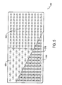
- Fig. 5 shows a hot gas flow channel plate face having a variable flow structure pattern in accordance with an exemplary embodiment
- Fig. 6 shows a side view of a plate having a variable flow structure pattern in accordance with an exemplary embodiment
- Fig. 7 shows a cross-sectional perspective view of a portion of a heat exchanger matrix in accordance with an exemplary embodiment.
- Fig. 8 shows a perspective view of a crossflow heat exchanger having a matrix in accordance with an exemplary embodiment.
- Fig. 1 shows a related art plate-type heat exchanger wherein the h values of cold gas stream 130 and hot gas stream 140 are not optimized and thus the metal plate temperature is uneven at hot gas exit plane 100. Specifically, the metal temperature at plate points 150a-150d deviate from one another substantially.
- FIG. 2 shows a diagrammatical cross-sectional view of the heat exchanger plate shown in Fig. 1 .
- Fig. 2 shows velocities of hot gas (represented by arrows 225) near or at hot gas exit plane 200, and velocities of entering cool gas 235, and specifically velocities of entering cool gas 235 at plate points 230a and 230b near or at the cool gas entry plane 275.
- cold gas stream 235 has a high velocity causing the plates to be coldest near cool gas entry plane 275 where a blast of cold air enters the heat exchanger.
- cool gas stream 235 has a velocity at plate point 230a of about 1000 ft/min, while the velocity of the cool gas stream 235 at plate point 230b is about 470 ft/min.
- the velocity of the exiting hot gas stream 225 may be relatively even across the vicinity of the hot gas exit plane 200, the velocity being about 585 ft/.in. If the cool gas stream 235 has a higher velocity at a plate point than does the hot gas stream 225, then the plate temperature may be influenced more by the cool air stream 235 and its temperature. Thus, and as shown in Fig. 1 , the exiting hot gas 150 may have a temperature that varies from a low near the vicinity of the cool air entry plane to a high at a portion of the plate distal to the cool air entry plane 175. Indeed, Fig. 1 shows declining exiting hot gas 150 temperatures from plate points 150d through 150a approaching the cool gas entry plane 175, plate point 150d being distal to cool gas entry plane 175.
- Spacing between the plates of a heat exchanger matrix may be defined by dimples, or other variably shaped protrusions (collectively referred to herein as variable flow structures), formed on the plates with a height that is typically half of the spacing between the plates.
- the dimples on opposing plates contact one another to define the plate spacing and provide structural support. That is, for a half-inch plate spacing, the dimple height on each plate would be a quarter inch.
- a variable flow structure pattern on a plate may be selected for the purpose of: (1) supporting the plates to withstand a pressure differential between the fluid streams to prevent the plates from collapsing onto one another as a result of high gas pressure; (2) increasing flow turbulence to enhance h; (3) decreasing turbulence to lower gas flow pressure drop; or (4) a combination of 1, 2 and 3 to control temperature and overall performance. While protrusions or dimples are discussed as exemplary variable flow structures, any structure that varies the velocity of an adjacent gas stream may constitute a variable flow structure in accordance with an exemplary embodiment.
- a related art heat exchanger has plates with dimples or protrusions that may be equally spaced or symmetrical, and may exhibit velocities and plate temperatures as shown in Figs. 1 and 2 .
- the hot gas temperature varies from a low at the cold gas entrance plane 175 to a high at the side opposite the inlet, e.g., plate point 150d.
- the hot gas streams have substantially equal velocity through the entire length of the heat exchanger because the dimples on the hot side are evenly spaced and arranged symmetrically over the entire plate surface.
- the cold gas streams are typically in a "U-flow" pattern and have differing velocities, a highest velocity corresponding to the shortest flow length and a lowest velocity corresponding to the longest flow length.
- Fig. 2 shows that the velocity of cool gas flow stream 180 of Fig. 1 (corresponding to flow stream 235 at plate point 230a) is more than two times the velocity of cool gas flow stream 185 of Fig. 1 (corresponding to flow stream 235 at plate point 230b).
- the cool gas has a greater influence on plate temperature along flow stream 180's path than along flow stream 185, and thus a lower exiting hot gas temperature (e.g., 450°F at plate point 150a) nearest the cool gas entry plane 175, as shown in Fig. 1 .
- Cool gas flow stream 185 has the opposite effect.
- hot gas flow stream 227 leaves the heat exchanger at a higher temperature (e.g., 800°F at plate point 150d) and affects the surrounding plate temperature accordingly.
- the temperature of the plate can be controlled to a degree by designing the variable flow structure pattern to influence gas flow distribution, and thus velocity throughout the heat exchanger. As discussed above, the higher the velocity of a gas stream, the higher the value of coefficient h of the gas stream. If h 4 of the hot gas is greater than h 1 of the cold gas, then the plate is influenced more by the hot gas stream temperature. Thus, as the heat transfer coefficient is changed, an effect on plate temperature, Tp may be observed.
- variable flow structure arrangement may change the velocity distribution of one or both of the cold gas stream and the hot gas stream in a manner that may optimize their values of h to effect a metal temperature that evens out at the hot gas exit plane.
- FIG. 3 shows counterflow plate heat exchanger configurations in accordance with exemplary embodiments.
- Variable flow structure arrangements may be applied in heat exchanger configurations other than "U-flow” such as "X-flow,” “K-flow,” and “L-flow.” These configurations are mentioned by way of example.
- species of both counterflow and crossflow configurations may be used.
- FIG. 4 shows a plate surface facing a cold gas stream having a preferred arrangement of protrusions or dimples, i.e., variable flow structures 410.
- a heat exchanger matrix in accordance with an exemplary embodiment may include a plate surface facing a cold gas stream having a variable flow structure arrangement that is symmetrical while a plate surface facing a hot gas stream has a variable flow structure arrangement arranged to optimize h 4 of the hot gas stream.
- the preferred variable flow structure arrangement of a plate surface facing a cold gas stream shown in Fig. 4 may effect idealized plate temperature, and may cause the h values of the hot and cold fluid streams to approach each other in value at any given x, y plate coordinate, thus increasing the overall performance of the heat exchanger.
- overall conductance U has a greater average value in matrices having plates with variable flow structures 410 arranged in accordance with an exemplary embodiment than matrices having plates with substantially symmetrical variable flow structure spacing. This results in less surface area being required in the heat exchanger to produce the same thermal performance, or conversely, for the same surface area the overall effectiveness of the heat exchanger matrix increases.
- the overall pressure drop, even with the increased performance remains essentially unchanged. Although uneven variable flow structure 410 spacing may lead to greater turbulence and greater pressure drop, this may be offset by greater plate spacing (less plates) to achieve the same effectiveness.
- the exemplary cold side plate surface 400 shown in Fig. 4 embodies a variable flow structure 410 pattern that is asymmetrical and achieves the advantages discussed immediately above.
- portion 440 of plate 400 has variable flow structures 410 arranged with a spacing between the variable flow structures 410 that is substantially equal throughout portion 440.
- the density of variable flow structures 410 differs between portions 420, 430, and 440.
- the spacing between variable flow structures 410 of portion 420 of plate 400 is much greater than the spacing between variable flow structures 410 of portion 430 of plate 400.
- Fig. 5 shows a preferred pattern arrangement of variable flow structures 510 of a plate surface facing a hot gas stream.
- the variable flow structures 510 of plate 500 may have different spacing therebetween among different portions of plate 500.
- spacing between variable flow structures 510 in portion 540 may be substantially equal throughout portion 540.
- the density of variable flow structures 510 of portion 520 may be substantially less than that of the variable flow structures 510 of portion 540, i.e., spacing between variable flow structures 510 of portion 520 may be greater than that of portion 540.
- the variable flow structure 510 density in portion 530 of plate 500 may be greater than that of portions 540 and 520.
- a heat exchanger having one or both of the variable pattern plate surfaces shown in Figs. 4 and 5 may effect a change in velocity of hot and cold gases to optimize the values of h for either or both the hot and cold gases to result in a metal temperature that is substantially even across plate points at or near a hot gas exit plane.
- Fig. 6 shows a side view of a plate having a variable flow structure pattern in accordance with an exemplary embodiment. From Fig. 6 it may be understood that variable flow structures 601 may be arranged on plate 600 such that variable flow structures 601 are arranged on a first surface 605 of plate 600 that may face a hot gas stream. Variable flow structures 601 may also be arranged on a second surface 610 of plate 600 that may face a cold gas stream. Thus, surfaces 605 and 610 may be formed on or defined by a single plate 600. Moreover, variable flow structures 601 may be formed on both surfaces 605 and 610 of a single plate 600. Thus, during manufacture, variable flow structures 601 may be formed from or on the same plate 600.
- Crossflow heat exchanger 700 may include a heat exchanger matrix 705 in accordance with an exemplary embodiment, including plates having variable flow structure patterns as described above. Specifically, crossflow heat exchanger 700 may have a cold gas flow stream inlet 710 and a corresponding cold gas flow stream outlet 720 where cold gas may enter and exit the heat exchanger matrix. Crossflow heat exchanger 700 may include a hot gas flow stream inlet 730 and a corresponding hot gas flow stream outlet 740. Plates 745 may be arranged to form a matrix 750. At least one plate 745 may include variable flow structures 753 arranged in a pattern that affects the velocity of flow streams passing over plate 745.
- variable flow structures 753 across plate 745 may affect the direction of and velocity of an adjacent gas flow stream and correspondingly affect the value of h for the flow stream.
- the value of h is optimized by way of the variable structure 753 pattern arrangement, the occurrence of cold spots on plate 745 may be reduced as the temperature of plate 745 across, for example, hot gas flow stream outlet 740 is made substantially even.
- Fig. 8 shows a perspective view of a crossflow heat exchanger 800.
- Fig. 8 shows a crossflow heat exchanger 800 that may include the matrix shown in Fig. 7 in accordance with an exemplary embodiment.
- Crossflow heat exchanger 800 may include a hot gas flow stream inlet 804 that may accommodate a hot gas flow in a first direction.
- Crossflow heat exchanger 800 may also include a cold gas flow stream inlet 806 that may accommodate cold gas flow in a second direction substantially perpendicular to the first direction of the hot gas air flow.
- An alternative embodiment may include a counterflow heat exchanger, as discussed above, without departing from the scope and spirit of the exemplary embodiments.
Landscapes
- Engineering & Computer Science (AREA)
- Physics & Mathematics (AREA)
- Thermal Sciences (AREA)
- Mechanical Engineering (AREA)
- General Engineering & Computer Science (AREA)
- Heat-Exchange Devices With Radiators And Conduit Assemblies (AREA)
Claims (10)
- Flüssigkeit-zu-Flüssigkeit-Wärmetauscher-Matrix, beinhaltend:eine erste Platte (745), die eine erste Oberfläche und eine zweite Oberfläche aufweist;eine zweite Platte (745), die eine erste Oberfläche und eine zweite Oberfläche aufweist, wobei die zweite Oberfläche der ersten Platte der ersten Oberfläche der zweiten Platte gegenüberliegt, um einen ersten Strömungskanal zu definieren;eine dritte Platte (745), die eine erste Oberfläche aufweist, die der zweiten Oberfläche der zweiten Platte gegenüberliegt, um einen zweiten Strömungskanal zu definieren;die erste Platte, die zweite Platte und die dritte Platte einen Abschnitt einer Plattenmatrix (705) beinhaltend, wobei die Matrix einen ersten Strömungseinlass (730) und einen ersten Strömungsauslass (740) in Kommunikation mit mindestens einem des ersten Strömungskanals und einen zweiten Strömungseinlass (710) und einen zweiten Strömungsauslass (720) in Kommunikation mit dem zweiten Strömungskanal aufweist; undwobei die zweite Oberfläche der ersten Platte (745) eine Vielzahl von variablen Strömungsstrukturen (753) aufweist, die in einer ersten Region und einer zweiten Region angeordnet sind, wobei die erste Region eine variable Strömungsstrukturdichte aufweist, die größer als eine variable Strömungsstrukturdichte der zweiten Region ist, um eine Geschwindigkeit einer Flüssigkeit, die über die erste und zweite Region im ersten Strömungskanal passiert, zu regeln,die zweite Oberfläche der zweiten Platte eine Vielzahl von variablen Strömungsstrukturen aufweist, die in einer ersten Region und einer zweiten Region angeordnet sind, wobei die erste Region eine variable Strömungsstrukturdichte aufweist, die größer als eine variable Strömungsstrukturdichte der zweiten Region ist, um eine Geschwindigkeit einer Flüssigkeit, die über die erste und zweite Region im zweiten Strömungskanal passiert, zu regeln;dadurch gekennzeichnet, dass die erste Region und die zweite Region der zweiten Oberfläche der ersten Platte andere Bereiche der Plattenmatrix definieren, in Draufsicht, als die erste Region und die zweite Region der zweiten Oberfläche der zweiten Platte.
- Flüssigkeit-zu-Flüssigkeit-Wärmetauscher-Matrix gemäß Anspruch 1, wobei der erste Strömungskanal Passage einer heißen Flüssigkeit unterbringt, die in eine erste Richtung strömt, und wobei der zweite Strömungskanal Passage einer kalten Flüssigkeit unterbringt, die in eine zweite Richtung strömt, die im Wesentlichen quer und entgegengesetzt zur ersten Richtung ist, wobei die erste Oberfläche der zweiten Platte (745) eine Vielzahl von variablen Strömungsstrukturen (753) aufweist, die in einer ersten Region und einer zweiten Region angeordnet sind, wobei die erste Region eine variable Strömungsstrukturdichte aufweist, die größer als eine variable Strömungsstrukturdichte der zweiten Region ist; und
wobei die Dichten der variablen Strömungsstrukturen der ersten Oberfläche der zweiten Platte und der zweiten Oberfläche der zweiten Platte die Geschwindigkeit der heißen Flüssigkeit und der kalten Flüssigkeit ändern, um dadurch einen Wärmeübergangskoeffizienten von einer der heißen Flüssigkeit und der kalten Flüssigkeit derart zu optimieren, dass eine Temperatur von mindestens einer der ersten Platte und der zweiten Platte über den zweiten Strömungsauslass im Wesentlichen gleich ist. - Flüssigkeit-zu-Flüssigkeit-Wärmetauscher-Matrix gemäß Anspruch 1, wobei der erste Strömungskanal Passage einer heißen Flüssigkeit unterbringt, die in eine erste Richtung strömt, und wobei der zweite Strömungskanal Passage einer kalten Flüssigkeit unterbringt, die in eine zweite Richtung im Wesentlichen entgegengesetzt zur ersten Richtung strömt, wobei die erste Oberfläche der zweiten Platte (745) eine Vielzahl von variablen Strömungsstrukturen (753) aufweist, die in einer ersten Region und einer zweiten Region angeordnet sind, wobei die erste Region eine variable Strömungsstrukturdichte aufweist, die größer als eine variable Strömungsstrukturdichte der zweiten Region ist;
wobei die variablen Strömungsstrukturen der ersten Oberfläche der zweiten Platte und der zweiten Oberfläche der zweiten Platte die Geschwindigkeit von mindestens einer der heißen Flüssigkeit und der kalten Flüssigkeit regeln, um dadurch einen Wärmeübergangskoeffizienten von einer der heißen Flüssigkeit und der kalten Flüssigkeit derart zu optimieren, dass eine Temperatur von mindestens einer der ersten Platte und der zweiten Platte geregelt wird, um ein Auftreten eines Kaltpunktes über den zweiten Strömungsauslass zu minimieren. - Flüssigkeit-zu-Flüssigkeit-Wärmetauscher-Matrix gemäß einem der vorhergehenden Ansprüche, die erste Oberfläche der zweiten Platte weiter beinhaltend:eine Vielzahl von variablen Strömungsstrukturen (753), die in einer ersten Region und einer zweiten Region angeordnet sind, wobei die erste Region eine variable Strömungsstrukturdichte aufweist, die größer als eine variable Strömungsstrukturdichte der zweiten Region ist,wobei die variablen Strömungsstrukturen der ersten und zweiten Platte Vorsprünge sind und wobei einige der Vielzahl von Vorsprüngen der zweiten Platte einige der Vielzahl von Vorsprüngen der ersten Platte kontaktieren, wobei die Matrix strukturell gestützt ist.
- Flüssigkeit-zu-Flüssigkeit-Wärmetauscher-Matrix gemäß einem der Ansprüche 1 bis 4, wobei die erste Platte weiter beinhaltend:einen ersten Abschnitt der ersten Platte und einen zweiten Abschnitt der ersten Platte, die sich beide am zweiten Strömungsauslass befinden, wobei die Vielzahl von variablen Strömungsstrukturen angeordnet sind, um ein Auftreten einer Temperatur des ersten Plattenabschnitts zu vermeiden, die niedriger als eine Temperatur des zweiten Plattenabschnitts ist.
- Verfahren zum Ausgleichen der Temperaturen der Austrittsflächenplatte in der Flüssigkeit-zu-Flüssigkeit-Wärmetauscher-Matrix gemäß Anspruch 1 wobei der erste Strömungskanal Passage einer relativ heißen Flüssigkeit unterbringt und der zweite Strömungskanal Passage eine relativ kalten Flüssigkeit unterbringt; das Verfahren beinhaltend:Varüeren eine Geschwindigkeit der Flüssigkeit, die mindestens einen des ersten und zweiten Strömungskanals passiert, wobei eine Temperatur von mindestens einer der ersten und zweiten Oberfläche der ersten Platte oder der zweiten Platte oder der ersten Oberfläche der dritten Platte über mindestens einen des ersten und zweiten Strömungsauslasses im Wesentlichen gleich ist.
- Verfahren zum Ausgleichen der Temperatur der Austrittsflächenplatte gemäß Anspruch 6, das Verfahren weiter beinhaltend Varüeren der Geschwindigkeit von mindestens einer einer ersten und einer zweiten Flüssigkeit, die den ersten bzw. zweiten Strömungskanal passieren, wobei eine Temperatur an einem Punkt auf einer Oberfläche von mindestens einer der ersten Platte, der zweiten Platte und der dritten Platte im Wesentlichen gleich einem zweiten Punkt über mindestens einen des ersten und zweiten Strömungsauslasses der gleichen Oberfläche ist.
- Verfahren zum Ausgleichen der Temperatur der Austrittsflächenplatte gemäß Anspruch 6, das Verfahren weiter beinhaltend Optimieren des Wärmeübergangskoeffizienten von mindestens einer einer ersten Flüssigkeit und einer zweiten Flüssigkeit, die den ersten bzw. zweiten Strömungskanal passieren, durch variable Strömungsstrukturen, um eine Änderung der Temperatur an einem Punkt auf mindestens einer einer ersten Oberfläche und einer zweiten Oberfläche von mindestens einer einer ersten Platte, einer zweiten Platte und einer dritten Platte zu bewirken.
- Verfahren zum Ausgleichen der Temperatur der Austrittsflächenplatte gemäß Anspruch 6, das Verfahren weiter beinhaltend:Erhöhen einer Geschwindigkeit einer ersten Flüssigkeit, die einen eines ersten Strömungskanals und eines zweiten Strömungskanal passiert, um einen Wärmeübergangskoeffizienten der ersten Flüssigkeit zu optimieren; und Verringern einer Geschwindigkeit einer zweiten Flüssigkeit, die mindestens einen eines ersten Strömungskanals und eines zweiten Strömungskanals passiert, um einen Wärmeübergangskoeffizienten einer zweiten Flüssigkeit zu optimieren, wobei die Bildung von Kaltstellen auf einer Oberfläche von einem des ersten und zweiten Strömungskanals minimiert wird.
- Wärmetauscher, die Flüssigkeit-zu-Flüssigkeit-Wärmetauscher-Matrix gemäß einem der Ansprüche 1 bis 5 beinhaltend.
Applications Claiming Priority (1)
| Application Number | Priority Date | Filing Date | Title |
|---|---|---|---|
| US12/461,855 US9033030B2 (en) | 2009-08-26 | 2009-08-26 | Apparatus and method for equalizing hot fluid exit plane plate temperatures in heat exchangers |
Publications (3)
| Publication Number | Publication Date |
|---|---|
| EP2299228A2 EP2299228A2 (de) | 2011-03-23 |
| EP2299228A3 EP2299228A3 (de) | 2012-12-19 |
| EP2299228B1 true EP2299228B1 (de) | 2015-11-04 |
Family
ID=43242335
Family Applications (1)
| Application Number | Title | Priority Date | Filing Date |
|---|---|---|---|
| EP10173358.2A Active EP2299228B1 (de) | 2009-08-26 | 2010-08-19 | Vorrichtung und Verfahren zum Ausgleichen der Temperatur der Austrittsflächenplatte warmer Flüssigkeiten in Wärmetauschern |
Country Status (4)
| Country | Link |
|---|---|
| US (2) | US9033030B2 (de) |
| EP (1) | EP2299228B1 (de) |
| CN (1) | CN102003898A (de) |
| CA (1) | CA2712916C (de) |
Families Citing this family (19)
| Publication number | Priority date | Publication date | Assignee | Title |
|---|---|---|---|---|
| CN103148727A (zh) * | 2011-12-06 | 2013-06-12 | 杭州三花研究院有限公司 | 一种板式换热器的板片及板式换热器 |
| US9377250B2 (en) * | 2012-10-31 | 2016-06-28 | The Boeing Company | Cross-flow heat exchanger having graduated fin density |
| DE102013206248A1 (de) * | 2013-04-09 | 2014-10-09 | Behr Gmbh & Co. Kg | Stapelscheiben-Wärmetauscher |
| US9439325B2 (en) | 2013-10-21 | 2016-09-06 | International Business Machines Corporation | Coolant-cooled heat sink configured for accelerating coolant flow |
| DE112015000600T5 (de) | 2014-01-30 | 2016-11-10 | Dana Canada Corporation | Wärmetauscher mit abgestimmtem Durchfluss zum Batterie-Thermomanagement |
| EP3158271B1 (de) | 2014-06-20 | 2021-09-22 | Nortek Air Solutions Canada, Inc. | Systeme und verfahren zur verwaltung von bedingungen in geschlossenen räumen |
| US11092349B2 (en) | 2015-05-15 | 2021-08-17 | Nortek Air Solutions Canada, Inc. | Systems and methods for providing cooling to a heat load |
| EP3295088B1 (de) | 2015-05-15 | 2022-01-12 | Nortek Air Solutions Canada, Inc. | Verwendung eines flüssigkeit-zu-luft-membranenergieaustauschers zur flüssigkeitskühlung |
| US20170089643A1 (en) * | 2015-09-25 | 2017-03-30 | Westinghouse Electric Company, Llc. | Heat Exchanger |
| EP3400407A4 (de) | 2016-01-08 | 2019-08-07 | Nortek Air Solutions Canada, Inc. | Integrierte aussenluftanlage in einem 100%-igen luftumwälzungssystem |
| JP6485918B2 (ja) * | 2016-06-08 | 2019-03-20 | 株式会社アーカイブワークス | プレート型熱交換器 |
| EP3677866B1 (de) * | 2017-08-29 | 2026-01-21 | Welcon Inc. | Wärmetauscher |
| CN110763049B (zh) | 2018-07-26 | 2023-08-08 | 达纳加拿大公司 | 具有平行流动特征以增强热传导的热交换器 |
| CN111322888A (zh) * | 2018-12-13 | 2020-06-23 | 浙江盾安热工科技有限公司 | 换热器及具有其的空调器 |
| CN110926256B (zh) * | 2019-11-06 | 2022-03-08 | 华为数字能源技术有限公司 | 换热板以及包含该换热板的换热器 |
| DE102020212900A1 (de) * | 2020-02-04 | 2021-08-05 | Hanon Systems | Dimpel-Kühler mit Neben-Dimpeln |
| CN111342169B (zh) * | 2020-02-24 | 2022-07-22 | 江苏大学 | 一种车用高压加热系统的复合式疏水型水腔 |
| CN112050663A (zh) * | 2020-09-14 | 2020-12-08 | 刘延林 | 一种均匀化液冷式通风降温装置 |
| CN114705065B (zh) * | 2022-04-26 | 2025-08-05 | 济宁宽山钙业有限公司 | 一种化工生产用热交换器 |
Citations (1)
| Publication number | Priority date | Publication date | Assignee | Title |
|---|---|---|---|---|
| US3403724A (en) * | 1965-07-28 | 1968-10-01 | Gutkowski Janusz | Heat exchangers |
Family Cites Families (57)
| Publication number | Priority date | Publication date | Assignee | Title |
|---|---|---|---|---|
| US1826344A (en) * | 1930-09-23 | 1931-10-06 | Res & Dev Corp | Heat exchange element |
| US2306526A (en) * | 1938-11-30 | 1942-12-29 | Cherry Burrell Corp | Method of making heat exchange elements |
| US2481046A (en) * | 1947-11-13 | 1949-09-06 | Western Engineering Associates | Panel structure |
| US2959400A (en) * | 1957-11-27 | 1960-11-08 | Modine Mfg Co | Prime surface heat exchanger with dimpled sheets |
| US3340711A (en) * | 1965-03-11 | 1967-09-12 | Reynolds Metals Co | Hollow panel system |
| US3291206A (en) * | 1965-09-13 | 1966-12-13 | Nicholson Terence Peter | Heat exchanger plate |
| US3706218A (en) * | 1970-05-25 | 1972-12-19 | William B Elmer | Patterned diffuse reflecting |
| US3759323A (en) * | 1971-11-18 | 1973-09-18 | Caterpillar Tractor Co | C-flow stacked plate heat exchanger |
| US4049051A (en) * | 1974-07-22 | 1977-09-20 | The Garrett Corporation | Heat exchanger with variable thermal response core |
| US4044820A (en) | 1976-05-24 | 1977-08-30 | Econo-Therm Energy Systems Corporation | Method and apparatus for preheating combustion air while cooling a hot process gas |
| SE418058B (sv) * | 1978-11-08 | 1981-05-04 | Reheat Ab | Forfarande och anordning for pregling av vermevexlarplattor for plattvermevexlare |
| US4243096A (en) | 1979-04-09 | 1981-01-06 | Lipets Adolf U | Multipass corrosion-proof air heater |
| SE426341C (sv) | 1980-02-14 | 1985-09-23 | Fagersta Ab | Sett att forhindra korrosion i en forbrenningsanleggnings kylare och skorsten vid kylning av rokgaser |
| FI62866C (fi) * | 1980-03-03 | 1983-03-10 | Outokumpu Oy | Saett och anordning foer foerstyvning och raetning av startplaotar |
| DE3423736A1 (de) * | 1984-06-28 | 1986-01-02 | M.A.N. Maschinenfabrik Augsburg-Nürnberg AG, 8900 Augsburg | Kreuzstrom-plattenwaermetauscher |
| US4569391A (en) * | 1984-07-16 | 1986-02-11 | Harsco Corporation | Compact heat exchanger |
| JPS62252891A (ja) * | 1986-04-25 | 1987-11-04 | Sumitomo Heavy Ind Ltd | 向流式浮動プレ−ト型熱交換器 |
| US4978583A (en) * | 1986-12-25 | 1990-12-18 | Kawasaki Steel Corporation | Patterned metal plate and production thereof |
| JPH0760073B2 (ja) | 1987-08-25 | 1995-06-28 | 松下精工株式会社 | 全熱交換器 |
| US4862952A (en) | 1988-05-09 | 1989-09-05 | United Technologies Corporation | Frost free heat exchanger |
| SE463482B (sv) * | 1988-09-06 | 1990-11-26 | Pm Luft | Plattvaermevaexlare foer korsstroem daer varje plattmellanrum innefattar parallella stroemningskanaler, varvid, i syfte att foerhindra isbildning, vaermeavgivningsfoermaagan foer det varmare mediets kanaler oekar i det kallare mediets stroemningsriktning |
| US5172759A (en) * | 1989-10-31 | 1992-12-22 | Nippondenso Co., Ltd. | Plate-type refrigerant evaporator |
| US4971137A (en) * | 1989-11-09 | 1990-11-20 | American Energy Exchange, Inc. | Air-to-air heat exchanger with frost preventing means |
| JP2898361B2 (ja) | 1990-06-22 | 1999-05-31 | 株式会社東芝 | 空気調和機の室内ユニット |
| US5060722A (en) | 1990-11-06 | 1991-10-29 | American Standard, Inc. | Furnace heat exchanger |
| JPH06123590A (ja) | 1992-10-09 | 1994-05-06 | Mitsubishi Heavy Ind Ltd | 積層型熱交換器 |
| JPH06123589A (ja) | 1992-10-09 | 1994-05-06 | Mitsubishi Heavy Ind Ltd | 積層型熱交換器 |
| US5323850A (en) | 1993-03-29 | 1994-06-28 | Roberts Thomas H | Steam coil with alternating row opposite end feed |
| JPH0942865A (ja) * | 1995-07-28 | 1997-02-14 | Honda Motor Co Ltd | 熱交換器 |
| GB2311949A (en) | 1996-03-26 | 1997-10-15 | Hadley Ind Plc | Rigid thin sheet material |
| US5947812A (en) | 1996-08-21 | 1999-09-07 | Henning; Steven A. | Air return bulkhead for refrigeration trailers |
| KR100328277B1 (ko) * | 1996-10-17 | 2002-03-16 | 가와모토 노부히코 | 열교환기 |
| US6167948B1 (en) | 1996-11-18 | 2001-01-02 | Novel Concepts, Inc. | Thin, planar heat spreader |
| DE69812671T2 (de) * | 1997-01-27 | 2003-11-06 | Honda Motor Co Ltd | Wärmetauscher |
| FR2769974B1 (fr) | 1997-10-20 | 2000-01-07 | Valeo Climatisation | Evaporateur a capacite d'echange de chaleur amelioree |
| US6167952B1 (en) | 1998-03-03 | 2001-01-02 | Hamilton Sundstrand Corporation | Cooling apparatus and method of assembling same |
| AU737233B2 (en) * | 1998-03-24 | 2001-08-16 | Hunter Douglas Industries B.V. | Roll-patterned strip |
| US5937519A (en) | 1998-03-31 | 1999-08-17 | Zero Corporation | Method and assembly for manufacturing a convoluted heat exchanger core |
| FR2788123B1 (fr) * | 1998-12-30 | 2001-05-18 | Valeo Climatisation | Evaporateur, appareil de chauffage et/ou de climatisation et vehicule comportant un tel evaporateur |
| DE19902527B4 (de) | 1999-01-22 | 2009-06-04 | Hydro Aluminium Deutschland Gmbh | Druckplattenträger und Verfahren zur Herstellung eines Druckplattenträgers oder einer Offsetdruckplatte |
| CA2272804C (en) | 1999-05-28 | 2004-07-20 | Long Manufacturing Ltd. | Heat exchanger with dimpled bypass channel |
| US6318455B1 (en) | 1999-07-14 | 2001-11-20 | Mitsubishi Heavy Industries, Ltd. | Heat exchanger |
| US6161535A (en) | 1999-09-27 | 2000-12-19 | Carrier Corporation | Method and apparatus for preventing cold spot corrosion in induced-draft gas-fired furnaces |
| US6357396B1 (en) | 2000-06-15 | 2002-03-19 | Aqua-Chem, Inc. | Plate type heat exchanger for exhaust gas heat recovery |
| DE10034343C2 (de) * | 2000-07-14 | 2003-04-24 | Balcke Duerr Energietech Gmbh | Plattenwärmetauscher |
| FR2826439B1 (fr) | 2001-06-26 | 2003-10-03 | Valeo Climatisation | Echangeur de chaleur, en particulier evaporateur, a perfermances ameliores |
| US6938688B2 (en) | 2001-12-05 | 2005-09-06 | Thomas & Betts International, Inc. | Compact high efficiency clam shell heat exchanger |
| WO2004042306A2 (en) | 2002-11-01 | 2004-05-21 | Cooligy, Inc. | Method and apparatus for achieving temperature uniformity and hot spot cooling in a heat producing device |
| US7063047B2 (en) * | 2003-09-16 | 2006-06-20 | Modine Manufacturing Company | Fuel vaporizer for a reformer type fuel cell system |
| US7073573B2 (en) | 2004-06-09 | 2006-07-11 | Honeywell International, Inc. | Decreased hot side fin density heat exchanger |
| US20060231241A1 (en) | 2005-04-18 | 2006-10-19 | Papapanu Steven J | Evaporator with aerodynamic first dimples to suppress whistling noise |
| GB0509746D0 (en) | 2005-05-13 | 2005-06-22 | Ashe Morris Ltd | Variable plate heat exchangers |
| US7264045B2 (en) * | 2005-08-23 | 2007-09-04 | Delphi Technologies, Inc. | Plate-type evaporator to suppress noise and maintain thermal performance |
| US8276654B2 (en) * | 2005-11-17 | 2012-10-02 | Hamilton Sundstrand Corporation | Core assembly with deformation preventing features |
| US7879507B2 (en) | 2006-04-10 | 2011-02-01 | Protonex Technology Corporation | Insert-molded, externally manifolded, one-shot sealed membrane based electrochemical cell stacks |
| FR2900067B1 (fr) | 2006-04-20 | 2008-07-18 | Commissariat Energie Atomique | Systeme d'echangeur de chaleur comportant des zones de circulation fluidique revetues de facon selective par un catalyseur de reaction chimique |
| US8356658B2 (en) * | 2006-07-27 | 2013-01-22 | General Electric Company | Heat transfer enhancing system and method for fabricating heat transfer device |
-
2009
- 2009-08-26 US US12/461,855 patent/US9033030B2/en active Active
-
2010
- 2010-08-16 CA CA2712916A patent/CA2712916C/en active Active
- 2010-08-19 EP EP10173358.2A patent/EP2299228B1/de active Active
- 2010-08-26 CN CN2010102728744A patent/CN102003898A/zh active Pending
-
2012
- 2012-02-03 US US13/365,602 patent/US20120131796A1/en not_active Abandoned
Patent Citations (1)
| Publication number | Priority date | Publication date | Assignee | Title |
|---|---|---|---|---|
| US3403724A (en) * | 1965-07-28 | 1968-10-01 | Gutkowski Janusz | Heat exchangers |
Also Published As
| Publication number | Publication date |
|---|---|
| CA2712916A1 (en) | 2011-02-26 |
| CA2712916C (en) | 2017-07-25 |
| US9033030B2 (en) | 2015-05-19 |
| EP2299228A3 (de) | 2012-12-19 |
| US20120131796A1 (en) | 2012-05-31 |
| CN102003898A (zh) | 2011-04-06 |
| EP2299228A2 (de) | 2011-03-23 |
| US20110048687A1 (en) | 2011-03-03 |
Similar Documents
| Publication | Publication Date | Title |
|---|---|---|
| EP2299228B1 (de) | Vorrichtung und Verfahren zum Ausgleichen der Temperatur der Austrittsflächenplatte warmer Flüssigkeiten in Wärmetauschern | |
| JP6693690B2 (ja) | 熱交換器 | |
| US12510308B2 (en) | Heat augmentation features in a cast heat exchanger | |
| KR101072689B1 (ko) | 공냉식 공기 냉각기 | |
| US7077190B2 (en) | Exhaust gas heat exchanger | |
| EP3258204A1 (de) | Sammler für einen wärmetauscher | |
| EP3553446B1 (de) | Geformte vorderkante eines gussplatten-rippenwärmetauschers | |
| US8033326B2 (en) | Heat exchanger | |
| US20170198979A1 (en) | Heat exchangers | |
| US20050022982A1 (en) | Heat exchanger with flow director | |
| US11841195B2 (en) | Means for sensing temperature | |
| EP3734212B1 (de) | Asymmetrischer kreuzgegenstromwärmetauscher | |
| EP3176533B1 (de) | Querstromkeramikwärmetauscher und verfahren zur herstellung | |
| EP3734213B1 (de) | Versetzter/schräger kreuzgegenstrom-wärmetauscher | |
| EP4385736B1 (de) | Variable durchgänge für optimierung von delta p und wärmeübertragung entlang des strömungswegs | |
| EP3553448B1 (de) | Sekundär angewendetes kaltseitenfeatures für gegossenen wärmetauscher | |
| US10823111B2 (en) | Energy recovery unit for vehicle use | |
| JP7173929B2 (ja) | プレートフィン熱交換器の熱交換部及び熱交換システムの製造方法 | |
| US20070235174A1 (en) | Heat exchanger | |
| US11859918B2 (en) | Crossflow/counterflow subfreezing plate fin heat exchanger | |
| US20240418450A1 (en) | Multiple tube heat exchanger | |
| WO2025202959A1 (en) | A plate type gas-gas heat exchanger |
Legal Events
| Date | Code | Title | Description |
|---|---|---|---|
| PUAI | Public reference made under article 153(3) epc to a published international application that has entered the european phase |
Free format text: ORIGINAL CODE: 0009012 |
|
| AK | Designated contracting states |
Kind code of ref document: A2 Designated state(s): AL AT BE BG CH CY CZ DE DK EE ES FI FR GB GR HR HU IE IS IT LI LT LU LV MC MK MT NL NO PL PT RO SE SI SK SM TR |
|
| AX | Request for extension of the european patent |
Extension state: BA ME RS |
|
| PUAL | Search report despatched |
Free format text: ORIGINAL CODE: 0009013 |
|
| AK | Designated contracting states |
Kind code of ref document: A3 Designated state(s): AL AT BE BG CH CY CZ DE DK EE ES FI FR GB GR HR HU IE IS IT LI LT LU LV MC MK MT NL NO PL PT RO SE SI SK SM TR |
|
| AX | Request for extension of the european patent |
Extension state: BA ME RS |
|
| RIC1 | Information provided on ipc code assigned before grant |
Ipc: F28F 3/04 20060101ALI20121109BHEP Ipc: F28D 9/00 20060101AFI20121109BHEP Ipc: F28F 13/08 20060101ALI20121109BHEP |
|
| RAP1 | Party data changed (applicant data changed or rights of an application transferred) |
Owner name: MUNTERS CORPORATION |
|
| 17P | Request for examination filed |
Effective date: 20130617 |
|
| RBV | Designated contracting states (corrected) |
Designated state(s): AL AT BE BG CH CY CZ DE DK EE ES FI FR GB GR HR HU IE IS IT LI LT LU LV MC MK MT NL NO PL PT RO SE SI SK SM TR |
|
| 17Q | First examination report despatched |
Effective date: 20140428 |
|
| GRAP | Despatch of communication of intention to grant a patent |
Free format text: ORIGINAL CODE: EPIDOSNIGR1 |
|
| INTG | Intention to grant announced |
Effective date: 20150723 |
|
| GRAS | Grant fee paid |
Free format text: ORIGINAL CODE: EPIDOSNIGR3 |
|
| GRAA | (expected) grant |
Free format text: ORIGINAL CODE: 0009210 |
|
| AK | Designated contracting states |
Kind code of ref document: B1 Designated state(s): AL AT BE BG CH CY CZ DE DK EE ES FI FR GB GR HR HU IE IS IT LI LT LU LV MC MK MT NL NO PL PT RO SE SI SK SM TR |
|
| REG | Reference to a national code |
Ref country code: GB Ref legal event code: FG4D |
|
| REG | Reference to a national code |
Ref country code: CH Ref legal event code: EP |
|
| REG | Reference to a national code |
Ref country code: AT Ref legal event code: REF Ref document number: 759497 Country of ref document: AT Kind code of ref document: T Effective date: 20151115 |
|
| REG | Reference to a national code |
Ref country code: IE Ref legal event code: FG4D |
|
| REG | Reference to a national code |
Ref country code: DE Ref legal event code: R096 Ref document number: 602010028724 Country of ref document: DE |
|
| REG | Reference to a national code |
Ref country code: NL Ref legal event code: MP Effective date: 20151104 |
|
| REG | Reference to a national code |
Ref country code: LT Ref legal event code: MG4D |
|
| REG | Reference to a national code |
Ref country code: AT Ref legal event code: MK05 Ref document number: 759497 Country of ref document: AT Kind code of ref document: T Effective date: 20151104 |
|
| PG25 | Lapsed in a contracting state [announced via postgrant information from national office to epo] |
Ref country code: ES Free format text: LAPSE BECAUSE OF FAILURE TO SUBMIT A TRANSLATION OF THE DESCRIPTION OR TO PAY THE FEE WITHIN THE PRESCRIBED TIME-LIMIT Effective date: 20151104 Ref country code: LT Free format text: LAPSE BECAUSE OF FAILURE TO SUBMIT A TRANSLATION OF THE DESCRIPTION OR TO PAY THE FEE WITHIN THE PRESCRIBED TIME-LIMIT Effective date: 20151104 Ref country code: NL Free format text: LAPSE BECAUSE OF FAILURE TO SUBMIT A TRANSLATION OF THE DESCRIPTION OR TO PAY THE FEE WITHIN THE PRESCRIBED TIME-LIMIT Effective date: 20151104 Ref country code: HR Free format text: LAPSE BECAUSE OF FAILURE TO SUBMIT A TRANSLATION OF THE DESCRIPTION OR TO PAY THE FEE WITHIN THE PRESCRIBED TIME-LIMIT Effective date: 20151104 Ref country code: IS Free format text: LAPSE BECAUSE OF FAILURE TO SUBMIT A TRANSLATION OF THE DESCRIPTION OR TO PAY THE FEE WITHIN THE PRESCRIBED TIME-LIMIT Effective date: 20160304 Ref country code: NO Free format text: LAPSE BECAUSE OF FAILURE TO SUBMIT A TRANSLATION OF THE DESCRIPTION OR TO PAY THE FEE WITHIN THE PRESCRIBED TIME-LIMIT Effective date: 20160204 Ref country code: IT Free format text: LAPSE BECAUSE OF FAILURE TO SUBMIT A TRANSLATION OF THE DESCRIPTION OR TO PAY THE FEE WITHIN THE PRESCRIBED TIME-LIMIT Effective date: 20151104 |
|
| PG25 | Lapsed in a contracting state [announced via postgrant information from national office to epo] |
Ref country code: LV Free format text: LAPSE BECAUSE OF FAILURE TO SUBMIT A TRANSLATION OF THE DESCRIPTION OR TO PAY THE FEE WITHIN THE PRESCRIBED TIME-LIMIT Effective date: 20151104 Ref country code: SE Free format text: LAPSE BECAUSE OF FAILURE TO SUBMIT A TRANSLATION OF THE DESCRIPTION OR TO PAY THE FEE WITHIN THE PRESCRIBED TIME-LIMIT Effective date: 20151104 Ref country code: PL Free format text: LAPSE BECAUSE OF FAILURE TO SUBMIT A TRANSLATION OF THE DESCRIPTION OR TO PAY THE FEE WITHIN THE PRESCRIBED TIME-LIMIT Effective date: 20151104 Ref country code: FI Free format text: LAPSE BECAUSE OF FAILURE TO SUBMIT A TRANSLATION OF THE DESCRIPTION OR TO PAY THE FEE WITHIN THE PRESCRIBED TIME-LIMIT Effective date: 20151104 Ref country code: PT Free format text: LAPSE BECAUSE OF FAILURE TO SUBMIT A TRANSLATION OF THE DESCRIPTION OR TO PAY THE FEE WITHIN THE PRESCRIBED TIME-LIMIT Effective date: 20160304 Ref country code: GR Free format text: LAPSE BECAUSE OF FAILURE TO SUBMIT A TRANSLATION OF THE DESCRIPTION OR TO PAY THE FEE WITHIN THE PRESCRIBED TIME-LIMIT Effective date: 20160205 Ref country code: AT Free format text: LAPSE BECAUSE OF FAILURE TO SUBMIT A TRANSLATION OF THE DESCRIPTION OR TO PAY THE FEE WITHIN THE PRESCRIBED TIME-LIMIT Effective date: 20151104 |
|
| PG25 | Lapsed in a contracting state [announced via postgrant information from national office to epo] |
Ref country code: CZ Free format text: LAPSE BECAUSE OF FAILURE TO SUBMIT A TRANSLATION OF THE DESCRIPTION OR TO PAY THE FEE WITHIN THE PRESCRIBED TIME-LIMIT Effective date: 20151104 |
|
| REG | Reference to a national code |
Ref country code: DE Ref legal event code: R097 Ref document number: 602010028724 Country of ref document: DE |
|
| PG25 | Lapsed in a contracting state [announced via postgrant information from national office to epo] |
Ref country code: SM Free format text: LAPSE BECAUSE OF FAILURE TO SUBMIT A TRANSLATION OF THE DESCRIPTION OR TO PAY THE FEE WITHIN THE PRESCRIBED TIME-LIMIT Effective date: 20151104 Ref country code: SK Free format text: LAPSE BECAUSE OF FAILURE TO SUBMIT A TRANSLATION OF THE DESCRIPTION OR TO PAY THE FEE WITHIN THE PRESCRIBED TIME-LIMIT Effective date: 20151104 Ref country code: EE Free format text: LAPSE BECAUSE OF FAILURE TO SUBMIT A TRANSLATION OF THE DESCRIPTION OR TO PAY THE FEE WITHIN THE PRESCRIBED TIME-LIMIT Effective date: 20151104 Ref country code: RO Free format text: LAPSE BECAUSE OF FAILURE TO SUBMIT A TRANSLATION OF THE DESCRIPTION OR TO PAY THE FEE WITHIN THE PRESCRIBED TIME-LIMIT Effective date: 20151104 Ref country code: DK Free format text: LAPSE BECAUSE OF FAILURE TO SUBMIT A TRANSLATION OF THE DESCRIPTION OR TO PAY THE FEE WITHIN THE PRESCRIBED TIME-LIMIT Effective date: 20151104 |
|
| PLBE | No opposition filed within time limit |
Free format text: ORIGINAL CODE: 0009261 |
|
| STAA | Information on the status of an ep patent application or granted ep patent |
Free format text: STATUS: NO OPPOSITION FILED WITHIN TIME LIMIT |
|
| 26N | No opposition filed |
Effective date: 20160805 |
|
| PG25 | Lapsed in a contracting state [announced via postgrant information from national office to epo] |
Ref country code: SI Free format text: LAPSE BECAUSE OF FAILURE TO SUBMIT A TRANSLATION OF THE DESCRIPTION OR TO PAY THE FEE WITHIN THE PRESCRIBED TIME-LIMIT Effective date: 20151104 |
|
| PG25 | Lapsed in a contracting state [announced via postgrant information from national office to epo] |
Ref country code: BE Free format text: LAPSE BECAUSE OF FAILURE TO SUBMIT A TRANSLATION OF THE DESCRIPTION OR TO PAY THE FEE WITHIN THE PRESCRIBED TIME-LIMIT Effective date: 20151104 |
|
| PG25 | Lapsed in a contracting state [announced via postgrant information from national office to epo] |
Ref country code: MC Free format text: LAPSE BECAUSE OF FAILURE TO SUBMIT A TRANSLATION OF THE DESCRIPTION OR TO PAY THE FEE WITHIN THE PRESCRIBED TIME-LIMIT Effective date: 20151104 |
|
| REG | Reference to a national code |
Ref country code: CH Ref legal event code: PL |
|
| PG25 | Lapsed in a contracting state [announced via postgrant information from national office to epo] |
Ref country code: CH Free format text: LAPSE BECAUSE OF NON-PAYMENT OF DUE FEES Effective date: 20160831 Ref country code: LI Free format text: LAPSE BECAUSE OF NON-PAYMENT OF DUE FEES Effective date: 20160831 |
|
| REG | Reference to a national code |
Ref country code: FR Ref legal event code: ST Effective date: 20170428 |
|
| PG25 | Lapsed in a contracting state [announced via postgrant information from national office to epo] |
Ref country code: FR Free format text: LAPSE BECAUSE OF NON-PAYMENT OF DUE FEES Effective date: 20160831 |
|
| PG25 | Lapsed in a contracting state [announced via postgrant information from national office to epo] |
Ref country code: LU Free format text: LAPSE BECAUSE OF NON-PAYMENT OF DUE FEES Effective date: 20160819 |
|
| PG25 | Lapsed in a contracting state [announced via postgrant information from national office to epo] |
Ref country code: CY Free format text: LAPSE BECAUSE OF FAILURE TO SUBMIT A TRANSLATION OF THE DESCRIPTION OR TO PAY THE FEE WITHIN THE PRESCRIBED TIME-LIMIT Effective date: 20151104 Ref country code: HU Free format text: LAPSE BECAUSE OF FAILURE TO SUBMIT A TRANSLATION OF THE DESCRIPTION OR TO PAY THE FEE WITHIN THE PRESCRIBED TIME-LIMIT; INVALID AB INITIO Effective date: 20100819 |
|
| PG25 | Lapsed in a contracting state [announced via postgrant information from national office to epo] |
Ref country code: MT Free format text: LAPSE BECAUSE OF NON-PAYMENT OF DUE FEES Effective date: 20160831 Ref country code: MK Free format text: LAPSE BECAUSE OF FAILURE TO SUBMIT A TRANSLATION OF THE DESCRIPTION OR TO PAY THE FEE WITHIN THE PRESCRIBED TIME-LIMIT Effective date: 20151104 Ref country code: TR Free format text: LAPSE BECAUSE OF FAILURE TO SUBMIT A TRANSLATION OF THE DESCRIPTION OR TO PAY THE FEE WITHIN THE PRESCRIBED TIME-LIMIT Effective date: 20151104 |
|
| PG25 | Lapsed in a contracting state [announced via postgrant information from national office to epo] |
Ref country code: BG Free format text: LAPSE BECAUSE OF FAILURE TO SUBMIT A TRANSLATION OF THE DESCRIPTION OR TO PAY THE FEE WITHIN THE PRESCRIBED TIME-LIMIT Effective date: 20151104 |
|
| PG25 | Lapsed in a contracting state [announced via postgrant information from national office to epo] |
Ref country code: AL Free format text: LAPSE BECAUSE OF FAILURE TO SUBMIT A TRANSLATION OF THE DESCRIPTION OR TO PAY THE FEE WITHIN THE PRESCRIBED TIME-LIMIT Effective date: 20151104 |
|
| PGFP | Annual fee paid to national office [announced via postgrant information from national office to epo] |
Ref country code: GB Payment date: 20240624 Year of fee payment: 15 |
|
| PGFP | Annual fee paid to national office [announced via postgrant information from national office to epo] |
Ref country code: DE Payment date: 20240729 Year of fee payment: 15 Ref country code: IE Payment date: 20240716 Year of fee payment: 15 |
|
| REG | Reference to a national code |
Ref country code: DE Ref legal event code: R119 Ref document number: 602010028724 Country of ref document: DE |