EP2299231A2 - Module de fixation pour tuyaux d'échange thermique - Google Patents
Module de fixation pour tuyaux d'échange thermique Download PDFInfo
- Publication number
- EP2299231A2 EP2299231A2 EP10169523A EP10169523A EP2299231A2 EP 2299231 A2 EP2299231 A2 EP 2299231A2 EP 10169523 A EP10169523 A EP 10169523A EP 10169523 A EP10169523 A EP 10169523A EP 2299231 A2 EP2299231 A2 EP 2299231A2
- Authority
- EP
- European Patent Office
- Prior art keywords
- holding module
- heat exchanger
- recesses
- modules
- module half
- Prior art date
- Legal status (The legal status is an assumption and is not a legal conclusion. Google has not performed a legal analysis and makes no representation as to the accuracy of the status listed.)
- Granted
Links
- 238000000034 method Methods 0.000 claims abstract description 10
- 238000010276 construction Methods 0.000 description 4
- 210000003608 fece Anatomy 0.000 description 1
- 238000009434 installation Methods 0.000 description 1
Images


Classifications
-
- F—MECHANICAL ENGINEERING; LIGHTING; HEATING; WEAPONS; BLASTING
- F28—HEAT EXCHANGE IN GENERAL
- F28F—DETAILS OF HEAT-EXCHANGE AND HEAT-TRANSFER APPARATUS, OF GENERAL APPLICATION
- F28F9/00—Casings; Header boxes; Auxiliary supports for elements; Auxiliary members within casings
- F28F9/007—Auxiliary supports for elements
- F28F9/013—Auxiliary supports for elements for tubes or tube-assemblies
- F28F9/0131—Auxiliary supports for elements for tubes or tube-assemblies formed by plates
-
- Y—GENERAL TAGGING OF NEW TECHNOLOGICAL DEVELOPMENTS; GENERAL TAGGING OF CROSS-SECTIONAL TECHNOLOGIES SPANNING OVER SEVERAL SECTIONS OF THE IPC; TECHNICAL SUBJECTS COVERED BY FORMER USPC CROSS-REFERENCE ART COLLECTIONS [XRACs] AND DIGESTS
- Y10—TECHNICAL SUBJECTS COVERED BY FORMER USPC
- Y10T—TECHNICAL SUBJECTS COVERED BY FORMER US CLASSIFICATION
- Y10T29/00—Metal working
- Y10T29/49—Method of mechanical manufacture
- Y10T29/49826—Assembling or joining
Definitions
- the invention relates to a holding module for heat exchanger tubes, a frame for heat exchanger tubes with a plurality of holding modules and a method for setting up a frame for heat exchanger tubes.
- Heat exchangers in particular tube heat exchangers, are widely used to transfer heat energy from a medium to a second medium. Depending on the application, several tube heat exchangers are combined into individual sections.
- the tubular heat exchangers include z. B., as will be explained in more detail below, a heat exchanger tube, d. h., A jacket tube, in which a plurality of inner tubes are arranged, but at least an inner tube.
- the heat exchanger tubes are held by means of frames and shelves.
- the conventional racks have a high space requirement and, moreover, the production of such racks and their assembly is complicated and expensive.
- the known racks are set to a certain size and not flexibly expandable.
- the object of the present invention is to provide a device and a method by means of which heat exchanger tubes can be kept simpler, more space-saving and less expensive, wherein the device is in particular flexibly expandable.
- a holding module has a lower module half with a plurality of recesses, in each of which a heat exchanger tube can be inserted, and an upper holding module half, which also has a plurality of recesses and which can be placed on the lower holding module half such that their recesses oppose the recesses of the lower holding module half, in such a way in that the heat exchanger tubes are held in the recesses.
- a connecting element connects the upper and the lower half.
- the heat exchanger tube can be easily inserted and then the second half are placed on top.
- the structure of the frame takes place gradually along with the layering the heat exchanger tubes. It is layered layer by layer until a certain frame height is reached.
- the height can be flexibly adapted to specific requirements.
- the system can also be flexibly upgraded later on.
- the system can be expanded as required.
- the frame according to the invention is significantly cheaper than the known frame racks.
- the assembly of the individual modules is very simple and fast. In addition, there is an improved design.
- the connecting element which connects the upper and lower holding module half, a plug-in element which can be plugged onto the lower holding module half, wherein the upper holding module half is plugged onto the plug-in element.
- a connecting element is inexpensive and moreover, it allows easy installation.
- the plug element preferably runs in the longitudinal direction of the heat exchanger tubes and ensures a stable connection.
- the upper and lower holding module half are identical.
- the entire holding module can be made very inexpensive.
- the upper and / or lower holding module half is formed so that it has a substantially U-shaped cross section with two opposite side walls and a bottom therebetween, wherein the recesses are formed in the side walls.
- each module half has two bearing surfaces for the heat exchanger tube and allows the heat exchanger tube rests well. Due to the U-shaped design, the weight of the holding module can be substantially reduced.
- the plug element can, for. Example, be constructed so that it has at least two upper and / or at least two lower openings into which the side walls of the upper and lower holding module half can be inserted or the lower holding module half and / or the upper holding module half is constructed so that they have in the side walls openings into which the plug element can be inserted.
- a frame for the heat exchanger tubes has at least a first and a second unit, in each of which a plurality of modules are arranged one above the other, in which case the mutually parallel heat exchanger tubes of the first and the at least second unit.
- different numbers of units can be used.
- each level can be equipped differently.
- the units do not have to be completely filled.
- the modules arranged one above the other in the units can be fixed together by a fixing device.
- the modules z. B. have arranged through openings, into which then a fixing rod can be inserted from above.
- the individual modules arranged one above the other remain correctly aligned with each other.
- lateral cross struts for clamping can be arranged between the holding element units.
- the lowermost holding module half of each holding module unit may be fixedly connected to a floor frame.
- the lowermost holding module half has a firm hold and allows a safe construction of the modules to be arranged above it.
- a plurality of mutually spaced holding module halves are provided (step a). Then, the heat exchanger tubes are inserted into the recesses of the lower holding module halves (step b). Finally, the plurality of upper holding module halves are placed on the tubes, such that the recesses are turned towards and receive the tubes (step c). On the upper side of the upper half of the holding module, which has already been installed, a lower holding module half can then be placed in turn to produce a further module (step d). The steps d, b, c can be repeated until a desired frame height is reached.
- step a or b the holding module halves are fixed.
- at least one plug-in element can be inserted into the lower holding module half and the upper holding module half can be plugged onto the at least one plug-in element in step c.
- the modules arranged one above the other in a unit can then be fixed again to each other in order to obtain an overall stable system.
- FIG. 6 shows the basic structure of a heat exchanger tube 12.
- the heat exchanger tube 12 here comprises a jacket or outer tube 18 with a secondary inlet 13 and a secondary outlet 14.
- a plurality of inner tubes In the casing tube 18 a plurality of inner tubes, but at least one inner tube or tube bundle 17 are arranged which have a corresponding primary-side inlet 15 and outlet 16.
- the individual heat exchanger tubes 12 can be connected in series with each other in series, ie, that then, for example, the outlet 16 of a first heat exchanger tube to the inlet 15 of a subsequent, z. B. arranged parallel to it, heat exchanger tube is connected and the drain 14 with the inlet 13 of a subsequent tube.
- the interconnection of the inlets 15 and 16 operations can be done for example via pipe bends.
- the connection of the processes 14 with the inlets 13 can also be done by appropriate pipe connections.
- FIG. 1 shows a perspective view of a holding module for holding a plurality of mutually parallel heat exchanger tubes 12, which are not shown here for simplicity.
- a holding module 1 in this case comprises a lower holding module half 1b, which has a plurality of recesses 3b, in each of which a heat exchanger tube 12 can be inserted and an upper holding module half 1a, which has a plurality of recesses 3a, and which can be placed on the lower holding module half 1b, that the recesses 3a are opposite the recesses 3b, such that the heat exchanger tube can be held firmly in the recesses 3a, b.
- Recess 3a, b corresponds substantially to the outer diameter of the heat exchanger tube 12, such that the tube is held against slipping.
- the holding modules are designed such that one of the units 30, 31, 32, 33 serve as a fixed and the other as a loose bearing, so that the different thermal expansion of the individual heat exchanger tubes is compensated relative to the frame.
- each holding module half is formed so that it has a U-shaped cross section, so that the holding module 1 is hollow inside and has a low weight.
- the openings 3a, b are formed in the opposite side walls 5a, b and 6a, b of the module halves 1a, b. Between the side walls 5a, b and 6a, b is in each case a bottom 7a, b.
- six recesses 3a, b are provided for six heat exchanger tubes arranged parallel to one another in a plane.
- about two to ten such openings are provided side by side.
- Opposing openings 9a, b are provided in the two floors 7a, b, into which a fixing rod 20 (see FIG. 2) for fixing holding modules arranged one above the other is provided FIG. 5 ) can be inserted.
- a connecting element preferably a plug-in element 11
- the plug-in element can be plugged onto the lower holding module half 1b, with the holding module half 1a being pushed onto the plug-in element 1.
- a holding module 3 comprises such plug-in elements 11.
- the number of plug-in elements 11 depends on the size of the holding module.
- the plug-in element extends in the longitudinal direction of the heat exchanger tubes 12.
- the plug-in element has two openings 19a at the top and two openings 19b at the bottom.
- the side walls 6a, b and 5a, b are inserted.
- the lower holding module half 1b and the upper holding module half 1a in the side walls may have openings into which the plug element 11, which then requires no corresponding openings, can be inserted.
- Several holding modules 1 can be arranged one above the other, as shown FIG. 4 evident.
- FIG. 4 shows, for example, 3 holding modules 1 which are arranged one above the other, wherein in the construction of 3 heat exchanger tubes 12 were inserted and the individual halves were connected to each other via the plug-in elements 11. This results in a self-supporting unit.
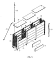
- FIG. 5 is a frame for heat exchanger tubes with a plurality of holding modules 1, as described above, shown.
- the holding modules 1 correspond to the holding modules described above.
- the heat exchanger tubes 12 are not shown.
- the frame has a plurality of units 30, 31, 32, in which a plurality of holding modules 1 are arranged one above the other. In this embodiment, four units are provided.
- the heat exchanger tubes 12 arranged in parallel are held by the holding modules in the respective units 30, 31, 32, 33.
- the lowermost holding module half 1b of each holding module unit 30 to 33 can be firmly fixed to a frame 27 which can stand on respective feet. Then, as many heat module halves and heat exchanger tubes are layered layer by layer until a desired height is reached.
- each unit can be fixed together by a fixing device 9, 20.
- a fixing device 9, 20 For this purpose, as already described above, in each module 1 a passage opening 9 (openings 9a, b in the bottom of the holding module halves) is provided. A fixing rod 20 is pushed through the openings and fastened for example by screwing. There are two fixing devices 20, 9 per unit.
- the stacked holding modules 1 can then, for. B. with cross braces 23 between the units 30, 31, 32, 33 are braced.
- the cross struts 23 can either (not shown) attach directly to the modules or with frame members 26 which are fastened between the units.
- side trim parts 21, 22 can be attached to the open sides of the frame.
- an upper panel 24 may be disposed between the individual units. Here, the upper panels 24, the openings 25 have above the corresponding openings 9, also held by the fixing rod 20.
- FIG. 7 shows a frame with fairing.
- the system according to the invention has the advantage that the number of heat exchanger tubes arranged in a plane can be varied, ie that, for example, not all recesses of tubes have to be occupied. Also, the number of stacked modules or tubes can be easily varied by stacking the desired number of modules one above the other.
- the heat exchanger tubes 12 via (not shown) and can be connected to each other depending on the interconnection via corresponding pipe bends or connecting elements, as well as in connection with FIG. 6 has been described. In this case, a connection can be made both vertically and horizontally. The center distance of the openings is the same for the same units.
- step a a more spaced apart lower holding module halves 1b.
- the holding module halves 1 b are attached to the frame 27.
- step b the heat exchanger tubes 12 are inserted into the lowermost heat exchanger half 1b of each unit 30, 31, 32, 33 (step b).
- An upper holding module half 1a is now placed on the tubes in each unit 30, 31, 32, 33 so that the recesses 3a are turned towards the tubes 12 and receive and hold them.
- step a or b the plug-in element 11 is inserted into the lower holding module half 1b, wherein the upper holding module half 1a is plugged into the plug element 11 in step c.
- a lower holding module half 1b of another module can be placed so that the bottom 7b comes to rest on the bottom 7a.
- the steps a, b, c can be repeated until a predetermined frame height is reached.
- the modules arranged one above the other in the individual units 30, 31, 32, 33, as explained above, can be fixed to one another via the fixing device 20, 9 by guiding and screwing the rod 20 through the openings 9.
- cross braces can still be arranged and, as desired, the elongate trim elements 21, the upper trim elements 24 and the lateral trim elements 22 are arranged.
- Frame parts 26 can be arranged between the individual units.
- the heat exchanger tubes can be mounted very easily. It results in a very appealing design.
- the modular structure is flexibly expandable in height.
- the compact design is extremely space-saving.
Landscapes
- Engineering & Computer Science (AREA)
- Physics & Mathematics (AREA)
- Thermal Sciences (AREA)
- Mechanical Engineering (AREA)
- General Engineering & Computer Science (AREA)
- Heat-Exchange Devices With Radiators And Conduit Assemblies (AREA)
- Air-Conditioning For Vehicles (AREA)
- Cooling Or The Like Of Electrical Apparatus (AREA)
- Details Of Heat-Exchange And Heat-Transfer (AREA)
Applications Claiming Priority (1)
| Application Number | Priority Date | Filing Date | Title |
|---|---|---|---|
| DE102009039816A DE102009039816A1 (de) | 2009-09-02 | 2009-09-02 | Haltemodul für Wärmetauscherrohre |
Publications (3)
| Publication Number | Publication Date |
|---|---|
| EP2299231A2 true EP2299231A2 (fr) | 2011-03-23 |
| EP2299231A3 EP2299231A3 (fr) | 2014-07-30 |
| EP2299231B1 EP2299231B1 (fr) | 2016-12-21 |
Family
ID=43242341
Family Applications (1)
| Application Number | Title | Priority Date | Filing Date |
|---|---|---|---|
| EP10169523.7A Not-in-force EP2299231B1 (fr) | 2009-09-02 | 2010-07-14 | Module de fixation pour tuyaux d'échange thermique |
Country Status (7)
| Country | Link |
|---|---|
| US (1) | US20110048674A1 (fr) |
| EP (1) | EP2299231B1 (fr) |
| CN (1) | CN102003910B (fr) |
| BR (1) | BRPI1003267A2 (fr) |
| DE (1) | DE102009039816A1 (fr) |
| DK (1) | DK2299231T3 (fr) |
| ES (1) | ES2612338T3 (fr) |
Families Citing this family (3)
| Publication number | Priority date | Publication date | Assignee | Title |
|---|---|---|---|---|
| CN102221304A (zh) * | 2011-07-28 | 2011-10-19 | 山东北辰压力容器有限公司 | 组装式矩形管束支持板 |
| DE102019135082A1 (de) * | 2019-12-19 | 2021-06-24 | Krones Aktiengesellschaft | Halterung für Wärmetauscherrohre |
| CN114543579B (zh) * | 2022-03-23 | 2024-02-13 | 株洲宏大高分子材料有限公司 | 一种氟塑料热交换器管束支撑结构 |
Family Cites Families (13)
| Publication number | Priority date | Publication date | Assignee | Title |
|---|---|---|---|---|
| US4202085A (en) * | 1978-11-30 | 1980-05-13 | Westinghouse Electric Corp. | Apparatus and method for installing rows of U-shaped tubes in a heat exchanger |
| AU5362079A (en) * | 1978-12-15 | 1980-09-04 | John Bernard Morrissey | Supports for heat exchanger tubes |
| DE3309430A1 (de) * | 1983-03-16 | 1984-09-20 | Helfrecht, Manfred, 8598 Waldershof | Waermesammler |
| JPS6294796A (ja) * | 1985-10-19 | 1987-05-01 | Nishida Marine Boiler Co Ltd | パイプ式熱交換器 |
| DE3928558A1 (de) * | 1989-08-29 | 1991-03-07 | Raimund Dr Rer Nat Oberschmid | Luft-luft-waermetauscher mit rippenrohr-klemmbloecken und spannvorrichtung bes. fuer landwirtschaftliche staelle |
| US5083372A (en) * | 1991-03-11 | 1992-01-28 | Power & Industrial Services Corp. | Method and apparatus for aligning and clamping a series of tubes in parallel |
| US5404941A (en) * | 1993-08-10 | 1995-04-11 | The Babcock & Wilcox Company | Split ring tube spacer assembly |
| DE4423765A1 (de) * | 1994-06-29 | 1996-01-04 | Albrecht Bauke | Abstandshalter von parallel angeordneten, flexiblen Kunststoffrohren zu Kühl- und Heizkunststoffmatten oder Kunststoffmatten für Wärmetauscher |
| JP4009001B2 (ja) * | 1998-02-25 | 2007-11-14 | 株式会社マーレ フィルターシステムズ | 内燃機関のegrガスクーラ |
| DE102006012164B4 (de) * | 2005-12-23 | 2009-12-17 | Fraunhofer-Gesellschaft zur Förderung der angewandten Forschung e.V. | Schaltungsanordnung zur Erzeugung einer Wechselspannung oder eines Wechselstroms |
| CN2911598Y (zh) * | 2006-05-18 | 2007-06-13 | 王建杰 | 新型散热器 |
| DE202006012164U1 (de) * | 2006-08-07 | 2006-10-12 | Babcock Borsig Service Gmbh | Abstandshalter für Wärmetauscher |
| DE102007017564A1 (de) * | 2007-04-12 | 2008-10-16 | Wallstein Ingenieur-Gesellschaft Mbh | Vorrichtung zur Distanzierung von Wärmetauscherrohren |
-
2009
- 2009-09-02 DE DE102009039816A patent/DE102009039816A1/de not_active Ceased
-
2010
- 2010-07-14 ES ES10169523.7T patent/ES2612338T3/es active Active
- 2010-07-14 DK DK10169523.7T patent/DK2299231T3/en active
- 2010-07-14 EP EP10169523.7A patent/EP2299231B1/fr not_active Not-in-force
- 2010-08-27 US US12/870,024 patent/US20110048674A1/en not_active Abandoned
- 2010-09-01 BR BRPI1003267-3A patent/BRPI1003267A2/pt not_active Application Discontinuation
- 2010-09-01 CN CN2010102720901A patent/CN102003910B/zh not_active Expired - Fee Related
Non-Patent Citations (1)
| Title |
|---|
| None |
Also Published As
| Publication number | Publication date |
|---|---|
| CN102003910A (zh) | 2011-04-06 |
| EP2299231B1 (fr) | 2016-12-21 |
| CN102003910B (zh) | 2012-12-12 |
| DK2299231T3 (en) | 2017-03-27 |
| ES2612338T3 (es) | 2017-05-16 |
| EP2299231A3 (fr) | 2014-07-30 |
| BRPI1003267A2 (pt) | 2012-05-29 |
| DE102009039816A1 (de) | 2011-03-03 |
| US20110048674A1 (en) | 2011-03-03 |
Similar Documents
| Publication | Publication Date | Title |
|---|---|---|
| EP3625496B1 (fr) | Véhicule muni d'un système de stockage servant à stocker et fournir un gaz sous pression et système de stockage pour véhicule | |
| DE69612581T2 (de) | Wärmetauscher mit U-Röhren, mit einer Anti-Auftrieb- und schwingungsneutralisierender Rohrhalterungsvorrichtung | |
| DE102012014775A1 (de) | Vorrichtung zur Anordnung von Batteriemodulen in einer Fahrzeugbatterie | |
| EP3499145B1 (fr) | Arrangement d'un dispositif de mise en température d'un espace sous un plafond | |
| DE1501618C3 (de) | Wärmeübertrager | |
| EP2299231B1 (fr) | Module de fixation pour tuyaux d'échange thermique | |
| DE69410215T2 (de) | Vorrichtung für schwingungsneutralisierendes Festsetzen von Wärmetauscherrohren und seine Verwendung | |
| DE69810221T2 (de) | Stützsystem für Rohrleitungen in technischen Anlagen, insbesondere in der Nuklearindustrie | |
| EP1947399A2 (fr) | Dispositif de climatisation de pièces et de bâtiments | |
| EP1936268A2 (fr) | Emetteur de vapeur suspendu | |
| DE2719676B2 (de) | Bauteilesatz für Gasverteilungseinrichtungen | |
| DE1501235A1 (de) | Verfahren und Einrichtung zum Kuehlen einer Kammer | |
| WO2005085737A1 (fr) | Dispositif pour echanger de la chaleur, et procede de production de ce dispositif | |
| DE10115841A1 (de) | Systemträger | |
| DE3045087A1 (de) | Waermeaustauscher | |
| DE2549052A1 (de) | Vorrichtung zur abstuetzung fuer plattenfoermige waermetauschermatrizen | |
| DE3110719C2 (de) | Wärmetauscher mit mehreren, in einem Gehäuse untergebrachten, spiralförmigen Verteilerrohrabschnitten | |
| DE1451270C3 (de) | Wärmeübertrager einer Kernreaktoranlage | |
| DE102019135082A1 (de) | Halterung für Wärmetauscherrohre | |
| DE4316875C2 (de) | Wärmetauscher, insbesondere Fließbetttrockner sowie Verfahren zu dessen Herstellung | |
| WO2008037309A1 (fr) | échangeur de chaleur | |
| EP4202341A2 (fr) | Ailettes d'échangeur de chaleur et leur procédé de fabrication | |
| DE1514501C (de) | Kernreaktoranlage mit Dampferzeuger | |
| EP1069391A2 (fr) | Radiateur avec éléments de support | |
| DE202013102811U1 (de) | Kaskadierbarer Rohrhalter und modulares Rohrhaltesystem |
Legal Events
| Date | Code | Title | Description |
|---|---|---|---|
| PUAI | Public reference made under article 153(3) epc to a published international application that has entered the european phase |
Free format text: ORIGINAL CODE: 0009012 |
|
| AK | Designated contracting states |
Kind code of ref document: A2 Designated state(s): AL AT BE BG CH CY CZ DE DK EE ES FI FR GB GR HR HU IE IS IT LI LT LU LV MC MK MT NL NO PL PT RO SE SI SK SM TR |
|
| AX | Request for extension of the european patent |
Extension state: BA ME RS |
|
| PUAL | Search report despatched |
Free format text: ORIGINAL CODE: 0009013 |
|
| AK | Designated contracting states |
Kind code of ref document: A3 Designated state(s): AL AT BE BG CH CY CZ DE DK EE ES FI FR GB GR HR HU IE IS IT LI LT LU LV MC MK MT NL NO PL PT RO SE SI SK SM TR |
|
| AX | Request for extension of the european patent |
Extension state: BA ME RS |
|
| RIC1 | Information provided on ipc code assigned before grant |
Ipc: F28F 9/013 20060101AFI20140625BHEP |
|
| 17P | Request for examination filed |
Effective date: 20140912 |
|
| RBV | Designated contracting states (corrected) |
Designated state(s): AL AT BE BG CH CY CZ DE DK EE ES FI FR GB GR HR HU IE IS IT LI LT LU LV MC MK MT NL NO PL PT RO SE SI SK SM TR |
|
| GRAP | Despatch of communication of intention to grant a patent |
Free format text: ORIGINAL CODE: EPIDOSNIGR1 |
|
| INTG | Intention to grant announced |
Effective date: 20160906 |
|
| GRAS | Grant fee paid |
Free format text: ORIGINAL CODE: EPIDOSNIGR3 |
|
| GRAA | (expected) grant |
Free format text: ORIGINAL CODE: 0009210 |
|
| AK | Designated contracting states |
Kind code of ref document: B1 Designated state(s): AL AT BE BG CH CY CZ DE DK EE ES FI FR GB GR HR HU IE IS IT LI LT LU LV MC MK MT NL NO PL PT RO SE SI SK SM TR |
|
| REG | Reference to a national code |
Ref country code: GB Ref legal event code: FG4D Free format text: NOT ENGLISH |
|
| REG | Reference to a national code |
Ref country code: CH Ref legal event code: EP |
|
| REG | Reference to a national code |
Ref country code: IE Ref legal event code: FG4D Free format text: LANGUAGE OF EP DOCUMENT: GERMAN |
|
| REG | Reference to a national code |
Ref country code: AT Ref legal event code: REF Ref document number: 855857 Country of ref document: AT Kind code of ref document: T Effective date: 20170115 |
|
| REG | Reference to a national code |
Ref country code: DE Ref legal event code: R096 Ref document number: 502010012908 Country of ref document: DE |
|
| PG25 | Lapsed in a contracting state [announced via postgrant information from national office to epo] |
Ref country code: LV Free format text: LAPSE BECAUSE OF FAILURE TO SUBMIT A TRANSLATION OF THE DESCRIPTION OR TO PAY THE FEE WITHIN THE PRESCRIBED TIME-LIMIT Effective date: 20161221 |
|
| REG | Reference to a national code |
Ref country code: DK Ref legal event code: T3 Effective date: 20170322 |
|
| REG | Reference to a national code |
Ref country code: SE Ref legal event code: TRGR |
|
| REG | Reference to a national code |
Ref country code: LT Ref legal event code: MG4D |
|
| REG | Reference to a national code |
Ref country code: NL Ref legal event code: MP Effective date: 20161221 |
|
| PG25 | Lapsed in a contracting state [announced via postgrant information from national office to epo] |
Ref country code: LT Free format text: LAPSE BECAUSE OF FAILURE TO SUBMIT A TRANSLATION OF THE DESCRIPTION OR TO PAY THE FEE WITHIN THE PRESCRIBED TIME-LIMIT Effective date: 20161221 Ref country code: NO Free format text: LAPSE BECAUSE OF FAILURE TO SUBMIT A TRANSLATION OF THE DESCRIPTION OR TO PAY THE FEE WITHIN THE PRESCRIBED TIME-LIMIT Effective date: 20170321 Ref country code: GR Free format text: LAPSE BECAUSE OF FAILURE TO SUBMIT A TRANSLATION OF THE DESCRIPTION OR TO PAY THE FEE WITHIN THE PRESCRIBED TIME-LIMIT Effective date: 20170322 |
|
| REG | Reference to a national code |
Ref country code: ES Ref legal event code: FG2A Ref document number: 2612338 Country of ref document: ES Kind code of ref document: T3 Effective date: 20170516 |
|
| PG25 | Lapsed in a contracting state [announced via postgrant information from national office to epo] |
Ref country code: HR Free format text: LAPSE BECAUSE OF FAILURE TO SUBMIT A TRANSLATION OF THE DESCRIPTION OR TO PAY THE FEE WITHIN THE PRESCRIBED TIME-LIMIT Effective date: 20161221 Ref country code: FI Free format text: LAPSE BECAUSE OF FAILURE TO SUBMIT A TRANSLATION OF THE DESCRIPTION OR TO PAY THE FEE WITHIN THE PRESCRIBED TIME-LIMIT Effective date: 20161221 |
|
| PG25 | Lapsed in a contracting state [announced via postgrant information from national office to epo] |
Ref country code: NL Free format text: LAPSE BECAUSE OF FAILURE TO SUBMIT A TRANSLATION OF THE DESCRIPTION OR TO PAY THE FEE WITHIN THE PRESCRIBED TIME-LIMIT Effective date: 20161221 |
|
| PG25 | Lapsed in a contracting state [announced via postgrant information from national office to epo] |
Ref country code: EE Free format text: LAPSE BECAUSE OF FAILURE TO SUBMIT A TRANSLATION OF THE DESCRIPTION OR TO PAY THE FEE WITHIN THE PRESCRIBED TIME-LIMIT Effective date: 20161221 Ref country code: CZ Free format text: LAPSE BECAUSE OF FAILURE TO SUBMIT A TRANSLATION OF THE DESCRIPTION OR TO PAY THE FEE WITHIN THE PRESCRIBED TIME-LIMIT Effective date: 20161221 Ref country code: IS Free format text: LAPSE BECAUSE OF FAILURE TO SUBMIT A TRANSLATION OF THE DESCRIPTION OR TO PAY THE FEE WITHIN THE PRESCRIBED TIME-LIMIT Effective date: 20170421 Ref country code: SK Free format text: LAPSE BECAUSE OF FAILURE TO SUBMIT A TRANSLATION OF THE DESCRIPTION OR TO PAY THE FEE WITHIN THE PRESCRIBED TIME-LIMIT Effective date: 20161221 Ref country code: RO Free format text: LAPSE BECAUSE OF FAILURE TO SUBMIT A TRANSLATION OF THE DESCRIPTION OR TO PAY THE FEE WITHIN THE PRESCRIBED TIME-LIMIT Effective date: 20161221 |
|
| PG25 | Lapsed in a contracting state [announced via postgrant information from national office to epo] |
Ref country code: PL Free format text: LAPSE BECAUSE OF FAILURE TO SUBMIT A TRANSLATION OF THE DESCRIPTION OR TO PAY THE FEE WITHIN THE PRESCRIBED TIME-LIMIT Effective date: 20161221 Ref country code: BG Free format text: LAPSE BECAUSE OF FAILURE TO SUBMIT A TRANSLATION OF THE DESCRIPTION OR TO PAY THE FEE WITHIN THE PRESCRIBED TIME-LIMIT Effective date: 20170321 Ref country code: SM Free format text: LAPSE BECAUSE OF FAILURE TO SUBMIT A TRANSLATION OF THE DESCRIPTION OR TO PAY THE FEE WITHIN THE PRESCRIBED TIME-LIMIT Effective date: 20161221 Ref country code: PT Free format text: LAPSE BECAUSE OF FAILURE TO SUBMIT A TRANSLATION OF THE DESCRIPTION OR TO PAY THE FEE WITHIN THE PRESCRIBED TIME-LIMIT Effective date: 20170421 |
|
| REG | Reference to a national code |
Ref country code: DE Ref legal event code: R097 Ref document number: 502010012908 Country of ref document: DE |
|
| PLBE | No opposition filed within time limit |
Free format text: ORIGINAL CODE: 0009261 |
|
| STAA | Information on the status of an ep patent application or granted ep patent |
Free format text: STATUS: NO OPPOSITION FILED WITHIN TIME LIMIT |
|
| 26N | No opposition filed |
Effective date: 20170922 |
|
| PG25 | Lapsed in a contracting state [announced via postgrant information from national office to epo] |
Ref country code: SI Free format text: LAPSE BECAUSE OF FAILURE TO SUBMIT A TRANSLATION OF THE DESCRIPTION OR TO PAY THE FEE WITHIN THE PRESCRIBED TIME-LIMIT Effective date: 20161221 |
|
| REG | Reference to a national code |
Ref country code: CH Ref legal event code: PL |
|
| GBPC | Gb: european patent ceased through non-payment of renewal fee |
Effective date: 20170714 |
|
| REG | Reference to a national code |
Ref country code: IE Ref legal event code: MM4A |
|
| REG | Reference to a national code |
Ref country code: FR Ref legal event code: ST Effective date: 20180330 |
|
| PG25 | Lapsed in a contracting state [announced via postgrant information from national office to epo] |
Ref country code: IE Free format text: LAPSE BECAUSE OF NON-PAYMENT OF DUE FEES Effective date: 20170714 Ref country code: CH Free format text: LAPSE BECAUSE OF NON-PAYMENT OF DUE FEES Effective date: 20170731 Ref country code: GB Free format text: LAPSE BECAUSE OF NON-PAYMENT OF DUE FEES Effective date: 20170714 Ref country code: LI Free format text: LAPSE BECAUSE OF NON-PAYMENT OF DUE FEES Effective date: 20170731 |
|
| PG25 | Lapsed in a contracting state [announced via postgrant information from national office to epo] |
Ref country code: FR Free format text: LAPSE BECAUSE OF NON-PAYMENT OF DUE FEES Effective date: 20170731 |
|
| REG | Reference to a national code |
Ref country code: BE Ref legal event code: MM Effective date: 20170731 |
|
| PG25 | Lapsed in a contracting state [announced via postgrant information from national office to epo] |
Ref country code: LU Free format text: LAPSE BECAUSE OF NON-PAYMENT OF DUE FEES Effective date: 20170714 |
|
| PG25 | Lapsed in a contracting state [announced via postgrant information from national office to epo] |
Ref country code: BE Free format text: LAPSE BECAUSE OF NON-PAYMENT OF DUE FEES Effective date: 20170731 |
|
| REG | Reference to a national code |
Ref country code: AT Ref legal event code: MM01 Ref document number: 855857 Country of ref document: AT Kind code of ref document: T Effective date: 20170714 |
|
| PG25 | Lapsed in a contracting state [announced via postgrant information from national office to epo] |
Ref country code: MT Free format text: LAPSE BECAUSE OF FAILURE TO SUBMIT A TRANSLATION OF THE DESCRIPTION OR TO PAY THE FEE WITHIN THE PRESCRIBED TIME-LIMIT Effective date: 20161221 |
|
| PG25 | Lapsed in a contracting state [announced via postgrant information from national office to epo] |
Ref country code: AT Free format text: LAPSE BECAUSE OF NON-PAYMENT OF DUE FEES Effective date: 20170714 |
|
| PG25 | Lapsed in a contracting state [announced via postgrant information from national office to epo] |
Ref country code: MC Free format text: LAPSE BECAUSE OF FAILURE TO SUBMIT A TRANSLATION OF THE DESCRIPTION OR TO PAY THE FEE WITHIN THE PRESCRIBED TIME-LIMIT Effective date: 20161221 Ref country code: HU Free format text: LAPSE BECAUSE OF FAILURE TO SUBMIT A TRANSLATION OF THE DESCRIPTION OR TO PAY THE FEE WITHIN THE PRESCRIBED TIME-LIMIT; INVALID AB INITIO Effective date: 20100714 |
|
| PG25 | Lapsed in a contracting state [announced via postgrant information from national office to epo] |
Ref country code: CY Free format text: LAPSE BECAUSE OF NON-PAYMENT OF DUE FEES Effective date: 20161221 |
|
| PG25 | Lapsed in a contracting state [announced via postgrant information from national office to epo] |
Ref country code: MK Free format text: LAPSE BECAUSE OF FAILURE TO SUBMIT A TRANSLATION OF THE DESCRIPTION OR TO PAY THE FEE WITHIN THE PRESCRIBED TIME-LIMIT Effective date: 20161221 |
|
| PG25 | Lapsed in a contracting state [announced via postgrant information from national office to epo] |
Ref country code: TR Free format text: LAPSE BECAUSE OF FAILURE TO SUBMIT A TRANSLATION OF THE DESCRIPTION OR TO PAY THE FEE WITHIN THE PRESCRIBED TIME-LIMIT Effective date: 20161221 |
|
| PG25 | Lapsed in a contracting state [announced via postgrant information from national office to epo] |
Ref country code: AL Free format text: LAPSE BECAUSE OF FAILURE TO SUBMIT A TRANSLATION OF THE DESCRIPTION OR TO PAY THE FEE WITHIN THE PRESCRIBED TIME-LIMIT Effective date: 20161221 |
|
| PGFP | Annual fee paid to national office [announced via postgrant information from national office to epo] |
Ref country code: DE Payment date: 20200630 Year of fee payment: 11 Ref country code: ES Payment date: 20200803 Year of fee payment: 11 Ref country code: DK Payment date: 20200710 Year of fee payment: 11 |
|
| PGFP | Annual fee paid to national office [announced via postgrant information from national office to epo] |
Ref country code: SE Payment date: 20200710 Year of fee payment: 11 Ref country code: IT Payment date: 20200610 Year of fee payment: 11 |
|
| REG | Reference to a national code |
Ref country code: DE Ref legal event code: R119 Ref document number: 502010012908 Country of ref document: DE |
|
| REG | Reference to a national code |
Ref country code: DK Ref legal event code: EBP Effective date: 20210731 |
|
| PG25 | Lapsed in a contracting state [announced via postgrant information from national office to epo] |
Ref country code: DE Free format text: LAPSE BECAUSE OF NON-PAYMENT OF DUE FEES Effective date: 20220201 |
|
| PG25 | Lapsed in a contracting state [announced via postgrant information from national office to epo] |
Ref country code: SE Free format text: LAPSE BECAUSE OF NON-PAYMENT OF DUE FEES Effective date: 20210715 |
|
| PG25 | Lapsed in a contracting state [announced via postgrant information from national office to epo] |
Ref country code: IT Free format text: LAPSE BECAUSE OF NON-PAYMENT OF DUE FEES Effective date: 20210714 Ref country code: DK Free format text: LAPSE BECAUSE OF NON-PAYMENT OF DUE FEES Effective date: 20210731 |
|
| REG | Reference to a national code |
Ref country code: ES Ref legal event code: FD2A Effective date: 20220926 |
|
| PG25 | Lapsed in a contracting state [announced via postgrant information from national office to epo] |
Ref country code: ES Free format text: LAPSE BECAUSE OF NON-PAYMENT OF DUE FEES Effective date: 20210715 |