EP2299517B1 - Système de batteries - Google Patents
Système de batteries Download PDFInfo
- Publication number
- EP2299517B1 EP2299517B1 EP10176787.9A EP10176787A EP2299517B1 EP 2299517 B1 EP2299517 B1 EP 2299517B1 EP 10176787 A EP10176787 A EP 10176787A EP 2299517 B1 EP2299517 B1 EP 2299517B1
- Authority
- EP
- European Patent Office
- Prior art keywords
- battery cell
- unit
- battery
- parameter
- cell management
- Prior art date
- Legal status (The legal status is an assumption and is not a legal conclusion. Google has not performed a legal analysis and makes no representation as to the accuracy of the status listed.)
- Active
Links
Images



Classifications
-
- H—ELECTRICITY
- H01—ELECTRIC ELEMENTS
- H01M—PROCESSES OR MEANS, e.g. BATTERIES, FOR THE DIRECT CONVERSION OF CHEMICAL ENERGY INTO ELECTRICAL ENERGY
- H01M10/00—Secondary cells; Manufacture thereof
- H01M10/42—Methods or arrangements for servicing or maintenance of secondary cells or secondary half-cells
-
- H—ELECTRICITY
- H01—ELECTRIC ELEMENTS
- H01M—PROCESSES OR MEANS, e.g. BATTERIES, FOR THE DIRECT CONVERSION OF CHEMICAL ENERGY INTO ELECTRICAL ENERGY
- H01M10/00—Secondary cells; Manufacture thereof
- H01M10/42—Methods or arrangements for servicing or maintenance of secondary cells or secondary half-cells
- H01M10/48—Accumulators combined with arrangements for measuring, testing or indicating the condition of cells, e.g. the level or density of the electrolyte
- H01M10/482—Accumulators combined with arrangements for measuring, testing or indicating the condition of cells, e.g. the level or density of the electrolyte for several batteries or cells simultaneously or sequentially
-
- H—ELECTRICITY
- H01—ELECTRIC ELEMENTS
- H01M—PROCESSES OR MEANS, e.g. BATTERIES, FOR THE DIRECT CONVERSION OF CHEMICAL ENERGY INTO ELECTRICAL ENERGY
- H01M10/00—Secondary cells; Manufacture thereof
- H01M10/42—Methods or arrangements for servicing or maintenance of secondary cells or secondary half-cells
- H01M10/425—Structural combination with electronic components, e.g. electronic circuits integrated to the outside of the casing
-
- H—ELECTRICITY
- H01—ELECTRIC ELEMENTS
- H01M—PROCESSES OR MEANS, e.g. BATTERIES, FOR THE DIRECT CONVERSION OF CHEMICAL ENERGY INTO ELECTRICAL ENERGY
- H01M10/00—Secondary cells; Manufacture thereof
- H01M10/42—Methods or arrangements for servicing or maintenance of secondary cells or secondary half-cells
- H01M10/48—Accumulators combined with arrangements for measuring, testing or indicating the condition of cells, e.g. the level or density of the electrolyte
- H01M10/486—Accumulators combined with arrangements for measuring, testing or indicating the condition of cells, e.g. the level or density of the electrolyte for measuring temperature
-
- H—ELECTRICITY
- H01—ELECTRIC ELEMENTS
- H01M—PROCESSES OR MEANS, e.g. BATTERIES, FOR THE DIRECT CONVERSION OF CHEMICAL ENERGY INTO ELECTRICAL ENERGY
- H01M50/00—Constructional details or processes of manufacture of the non-active parts of electrochemical cells other than fuel cells, e.g. hybrid cells
- H01M50/20—Mountings; Secondary casings or frames; Racks, modules or packs; Suspension devices; Shock absorbers; Transport or carrying devices; Holders
- H01M50/204—Racks, modules or packs for multiple batteries or multiple cells
- H01M50/207—Racks, modules or packs for multiple batteries or multiple cells characterised by their shape
- H01M50/209—Racks, modules or packs for multiple batteries or multiple cells characterised by their shape adapted for prismatic or rectangular cells
-
- H—ELECTRICITY
- H01—ELECTRIC ELEMENTS
- H01M—PROCESSES OR MEANS, e.g. BATTERIES, FOR THE DIRECT CONVERSION OF CHEMICAL ENERGY INTO ELECTRICAL ENERGY
- H01M50/00—Constructional details or processes of manufacture of the non-active parts of electrochemical cells other than fuel cells, e.g. hybrid cells
- H01M50/20—Mountings; Secondary casings or frames; Racks, modules or packs; Suspension devices; Shock absorbers; Transport or carrying devices; Holders
- H01M50/296—Mountings; Secondary casings or frames; Racks, modules or packs; Suspension devices; Shock absorbers; Transport or carrying devices; Holders characterised by terminals of battery packs
-
- H—ELECTRICITY
- H01—ELECTRIC ELEMENTS
- H01M—PROCESSES OR MEANS, e.g. BATTERIES, FOR THE DIRECT CONVERSION OF CHEMICAL ENERGY INTO ELECTRICAL ENERGY
- H01M50/00—Constructional details or processes of manufacture of the non-active parts of electrochemical cells other than fuel cells, e.g. hybrid cells
- H01M50/30—Arrangements for facilitating escape of gases
-
- G—PHYSICS
- G01—MEASURING; TESTING
- G01R—MEASURING ELECTRIC VARIABLES; MEASURING MAGNETIC VARIABLES
- G01R31/00—Arrangements for testing electric properties; Arrangements for locating electric faults; Arrangements for electrical testing characterised by what is being tested not provided for elsewhere
- G01R31/36—Arrangements for testing, measuring or monitoring the electrical condition of accumulators or electric batteries, e.g. capacity or state of charge [SoC]
- G01R31/396—Acquisition or processing of data for testing or for monitoring individual cells or groups of cells within a battery
-
- H—ELECTRICITY
- H01—ELECTRIC ELEMENTS
- H01M—PROCESSES OR MEANS, e.g. BATTERIES, FOR THE DIRECT CONVERSION OF CHEMICAL ENERGY INTO ELECTRICAL ENERGY
- H01M10/00—Secondary cells; Manufacture thereof
- H01M10/42—Methods or arrangements for servicing or maintenance of secondary cells or secondary half-cells
- H01M10/425—Structural combination with electronic components, e.g. electronic circuits integrated to the outside of the casing
- H01M2010/4271—Battery management systems including electronic circuits, e.g. control of current or voltage to keep battery in healthy state, cell balancing
-
- H—ELECTRICITY
- H01—ELECTRIC ELEMENTS
- H01M—PROCESSES OR MEANS, e.g. BATTERIES, FOR THE DIRECT CONVERSION OF CHEMICAL ENERGY INTO ELECTRICAL ENERGY
- H01M10/00—Secondary cells; Manufacture thereof
- H01M10/42—Methods or arrangements for servicing or maintenance of secondary cells or secondary half-cells
- H01M10/425—Structural combination with electronic components, e.g. electronic circuits integrated to the outside of the casing
- H01M2010/4278—Systems for data transfer from batteries, e.g. transfer of battery parameters to a controller, data transferred between battery controller and main controller
-
- H—ELECTRICITY
- H01—ELECTRIC ELEMENTS
- H01M—PROCESSES OR MEANS, e.g. BATTERIES, FOR THE DIRECT CONVERSION OF CHEMICAL ENERGY INTO ELECTRICAL ENERGY
- H01M50/00—Constructional details or processes of manufacture of the non-active parts of electrochemical cells other than fuel cells, e.g. hybrid cells
- H01M50/10—Primary casings; Jackets or wrappings
- H01M50/102—Primary casings; Jackets or wrappings characterised by their shape or physical structure
- H01M50/103—Primary casings; Jackets or wrappings characterised by their shape or physical structure prismatic or rectangular
-
- Y—GENERAL TAGGING OF NEW TECHNOLOGICAL DEVELOPMENTS; GENERAL TAGGING OF CROSS-SECTIONAL TECHNOLOGIES SPANNING OVER SEVERAL SECTIONS OF THE IPC; TECHNICAL SUBJECTS COVERED BY FORMER USPC CROSS-REFERENCE ART COLLECTIONS [XRACs] AND DIGESTS
- Y02—TECHNOLOGIES OR APPLICATIONS FOR MITIGATION OR ADAPTATION AGAINST CLIMATE CHANGE
- Y02E—REDUCTION OF GREENHOUSE GAS [GHG] EMISSIONS, RELATED TO ENERGY GENERATION, TRANSMISSION OR DISTRIBUTION
- Y02E60/00—Enabling technologies; Technologies with a potential or indirect contribution to GHG emissions mitigation
- Y02E60/10—Energy storage using batteries
Definitions
- the present invention relates to a battery system that manages a plurality of battery cells configuring an assembled battery.
- a plurality of CMUs are set by one per each of the battery cells or by one per some battery cells in the battery system so as to monitor the battery cells.
- a BMU Battery management Unit
- a BMU Battery management Unit
- BMU Battery Management Unit
- each of CMUs is managed by BMU (Battery Management Unit).
- a power generation system which includes a plurality of sets of direct current power sources and power converters which are connected to the direct current power sources to convert a direct current power into an alternative current power, the power converters being connected in parallel to supply the alternative current power to a system power supply, from the plurality of power converters in the system, one power converter is set as a master machine which detects an islanding operation state in which power supply from the system power supply is stopped, and setting is executed so as to cause the remaining power converters not to detect the islanding operation state.
- the master machine is selected from the power converters in operation in accordance with a predetermined condition, for example selecting the inverter having the highest generated power.
- a battery system which manages a plurality of battery cells of an assembled battery, comprising at least: a plurality of battery cells; and a plurality of battery cell management units, each of the battery cell management units being connected to each of the battery cells respectively and being electrically connected to each other, each of the battery cell management unit having an circuit for switching an operation mode of the battery cell management unit to a slave mode to be controlled by other battery cell management unit or a master mode to control other battery cell management unit on the basis of a parameter acquired from the plurality of battery cells.
- a battery system for example, an industrial vehicle such as a forklift, an electric vehicle, a hybrid vehicle, a moving vehicle such as an electric train, or a fixed power supply system such as a power supply system for a house can be exemplified,
- FIG. 1 is a diagram illustrating an example of the structure of a battery system according to a non-limited embodiment of the invention.
- a battery cell management system 100 has a structure in which a plurality of CMUs (Cell Monitoring Units) is connected with each other in parallel. Each of the CMUs is typically an electric circuit and executes a specific function described below.
- the battery cell management system 100 comprises CMUs 110a to 110z (hereinafter, generically referred to as CMUs 110).
- the CMUs 110a to 110z are connected in a one-to-one correspondence with battery cells 210a to 210z (hereinafter, generically referred to as battery cells 210) in an assembled battery 200.
- Each of the CMUs 110 individually monitors charging and discharging of the corresponding battery cell 210. In addition, these CMUs have the specific function.
- the CMU connected to the battery cell 210 with the least deterioration takes charge of the control of other CMUs each of which monitors corresponding battery cell 210. Therefore, it is possible to stably maintain a constant performance without reducing the overall process efficiency of the system.
- the CMUs are not always necessarily in a one-to-one correspondence with the battery cell 210, and the CMUs may be connected with each other in series.
- the CMU 110 can acquire several parameters (for example, a terminal voltage value and a case temperature value) whose values vary depending on an increase or decrease in the load applied to each of the battery cells 210.
- the parameters are indexes for measuring the degree of deterioration of each of the battery cells 210. It is possible to determine the most stable battery celt 210 by comparing the parameters acquired from each battery cell 210.
- the assembled battery 200 is connected to a power load (for example, an inverter or an electric motor) that is driven by electrical power, and the assembled battery 200 supplies the electrical power to the power load.
- the assembled battery 200 comprises a plurality of battery cell units 990 each of which has INPUT / OUTPUT port.
- One end of a communication cable (bus) 120 is connected one of the INPUT / OUTPUT ports, and the other end of the communication cable (bus) 120 is connected to a connection port (be discussed below).
- the assembled battery 200 is connected to, for example, a load control device through the connection port and then connected to a display device through the load control device. For example, when any parameter has an abnormal value, battery information such as the parameter may be displayed on a driver's meter panel of an electric vehicle to call the driver's attention to the battery that is likely to have a defect.
- the battery cell management system 100 and the assembled battery 200 are electrically connected to the load control device and the power load to form one battery system, for example, an industrial vehicle such as a forklift, an electric vehicle, a hybrid vehicle, or an electric train, or a fixed power supply system for household use.
- an industrial vehicle such as a forklift, an electric vehicle, a hybrid vehicle, or an electric train, or a fixed power supply system for household use.
- the CMU 110 has, for example, two operation modes. That is, one operation mode is a master mode in which the CMU 110 monitors and controls charging and discharging of the battery cell 210 connected to the CMU 110 and controls the operation of other CMU 110.
- the other operation mode is a slave mode in which the CMU 110 is controlled by another CMU 110 to monitor and control charging and discharging of the corresponding battery cell 210 connected to the CMU 110.
- the CMU 110 is not constantly operated only in one operation mode, but switches its operation mode according to a condition of the assembled battery 200.
- the CMU 110 connected to the corresponding battery cell 210 which has the least deterioration state is operated in the master mode. Therefore, one of the plurality of CMUs 110 in the battery cell management system 100 executes an operation in the master mode and the other CMU 110 executes an operation in the slave mode.
- the CMU 110 in the master mode manages other CMU 110. Therefore, in general, the battery system according to this embodiment can operate without a BMU (Battery Management Unit) that is separately incorporated in the battery management system 100 in order to manage the CMUs 110.
- BMU Battery Management Unit
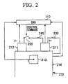
- FIG. 2 is a diagram illustrating an example of the connection structure between the battery cell 210 and the CMU 110.
- a temperature measuring circuit 213 is attached on a surface of a case body 214 of the battery cell 210.
- the temperature measuring circuit 213 comprises a sensor that measures the temperature of the battery cell 210.
- the CMU 110 acquires data indicating the temperature value of the battery cell 210 measured by the temperature measuring circuit 213.
- the CMU 110 detects the potential value of a positive terminal 211 with respect to a reference potential.
- the CMU 110 detects the voltage value between the positive terminal 211 and a negative terminal 212.
- the case body 214 and the positive terminal 211 are connected to each other with a resistor 230 interposed therebetween in order to generate a significant potential value to the case body 214.
- the CMU 110 may be configured so as to detect the potential value of the case body 214.
- the battery system may comprise a balance circuit for a voltage balance.
- the balance circuit is operated to reduce the voltage value of particular battery cell 210 so as to balance each voltage value of the battery cells 210.
- the balance circuit comprises, for example, a switch 250 that switches the on/off of the connection between the positive terminal 211 and the negative terminal 212 with the resistor 240 interposed therebetween.
- the balance circuit turns on or off the switch 250 in response to a control command from the CMU 110.
- Each CMU 110 in the slave mode monitors the voltage value of the corresponding battery cell 210 and transmits data indicating the voltage value and address information of the CMU 110 to the CMU 110 in the master mode through the communication cable 120 at a predetermined time interval or according to the request from the CMU 110 in the master mode.
- the CMU 110 in the master mode compare the voltage values of the battery cells 210 indicated by the data received from each CMU 110. As a result of the comparison, when there is the difference between the voltage values of the battery cells 210, the CMU 110 transmits a command to operate the balance circuit to the CMU 110 that manages the battery cell 210 with a high voltage together with the address information of the CMU 110 through the communication cable 120. Since the communication cable 120 is connected in series or parallel to each CMU 110, all of then CMUs 110 in the slave mode receive the command, and only the CMU 110 corresponding to the address information executes the command. Thus, the CMU 110 corresponding to the address information transmits a control command to make the balance circuit turns on the switch 250. Then, the balance circuit receives the control command and turns on the switch 250.
- FIG. 3 is a perspective view illustrating a battery cell unit 990 including a cover unit 900 for attaching the CMU 110 to the battery cell 210.
- FIG. 4 is a perspective view illustrating the cover unit 900 which is disassembled in the vertical direction in the battery cell unit 990 shown in FIG. 3 .
- the cover unit 900 is made of an insulating material, such as plastic or rubber. If the cover unit 900 is made by using plastic or rubber, it is easy to form the cover unit 900 with a mold. Therefore, it is desirable to use such plastic or rubber for manufacturing the following structure.
- the battery cell unit 990 is preferably applied to a battery system under the condition that, for example, (1) the battery system comprises a plurality of battery cells 210 and a plurality of CMUs 110, (2) one battery cell 210 and one CMU 110 are electrically connected with each other in a one-to-one correspondence, and (3) the plurality of CMUs 110 are electrically connected with each other in parallel.
- the battery cell unit 990 has structure for placing the battery cell 210 and the CMU 110 in the cover unit 900.
- the cover unit 900 may be divided into an upper cover 910 and a lower cover 920. It is easy to operate the structure since the battery cell 210 and the CMU 11 are integrally formed so that the battery cell 210 and the CMU 110 are connected in a one-to-one correspondence with each other, that is, one battery cell and one CMU are used as one set.
- the upper cover 910 comprises a concave portion 918 to which an upper part of the battery cell 210 is fitted.
- Supports 919a to 919d (hereinafter, genetically referred to as supports 919) are formed at four corners of the upper cover 910 so as to extend downward.
- Holes 911 and 912 through which the positive terminal 211 and the negative terminal 212 of the battery cell 210 pass when the battery cell 210 is fitted are formed in the upper part of the upper cover 910. In this way, when the battery cell 210 is fitted to the concave portion 918 of the upper cover 910, a portion of the leading end of each of the positive terminal 211 and the negative terminal 212 of the battery cell 210 is exposed to the outside of the main body of the upper cover 910.
- a hole 915 through which gas is discharged to the outside when a safety valve 215 is released is formed in the upper cover at a position where it faces the safety valve 215 of the battery cell 210 when the battery cell 210 is fitted to the concave portion 918 of the upper cover 910.
- a metal terminal 913 that is electrically connected to the temperature measuring circuit 213 of the battery cell 210 when the battery cell 210 is fitted is placed on the side surface of the upper cover 910.
- metal contacts 916a and 916b (hereinafter, generically referred to as metal contacts 916) that are electrically connected to the positive terminal 211 and the negative terminal 212 of the battery cell 210 are placed around the holes 911 and 912 of the upper cover 910, respectively.
- Input/output connectors 917a and 917b (hereinafter, generically referred to as input/output connectors 917) are formed on the upper surface of the upper cover 910. Connectors of the communication cable 120 for transmitting or receiving data are connected to the input/output connectors 917a and 917b. Connectors at the other end of the communication cable 120 are connected to the input/output connectors 917 of another cover unit 900.
- An internal bus is arranged between the input/output connectors 917a and 917b of the upper cover 910 so as to directly connect the connectors in the upper cover without any device interposed therebetween. Therefore, the cover units 900 are connected to each other by the communication cable 120 and the CMUs are electrically connected each other in parallel by the communication cable 120. Since a portion of the communication cable 120 is configured in the upper cover 910, it is possible to improve flexibility in the formation of the communication cable 120. Therefore, it is possible to meet the demand for a reduction in the size of a system, such as an electric vehicle in which the battery cell management system 100 and the assembled battery 200 need to be placed in a very narrow range.
- Metal terminals 914a to 914d (hereinafter, generically referred to as metal terminals 914) are placed on the leading end surfaces of the supports 919a to 919d of the upper cover 910, respectively.
- the leading end surfaces of the supports 919 are respectively facing to a leading end surface of a supports 929 (be discussed below).
- the metal terminals 914a to 914d are electrically connected to the metal terminal 913, the metal contacts 916a and 916b, or the balance circuit (not shown). In addition, the metal terminals 914a to 914d are electrically connected to one of the input/output connectors 917a. and 917b or the internal bus. Since the input/output connectors 917a and 917b are connected to the communication cable 120, it is desirable to use multi-pin connectors for the input/output connectors 917a and 917b.
- the metal terminal 914 since there are electrical connection to the metal terminal 914 and the two metal contacts (916a and 916b) and electrical connection for controlling the balance circuit, at least four or more electric paths are formed between the upper cover and the CMU 110 of the lower cover 920, which will be described below, through the four supports 919a to 919d. Therefore, some or all of the metal terminals 914 are multi-pin terminals (or multi-pin connectors) capable of transmitting a plurality of electric signals.
- a concave portion 928 to which a lower part of the battery cell 210 is fitted is formed in the lower cover 920.
- Supports 929a to 929d (hereinafter, generically referred to as supports 929) are formed at four corners of the lower cover 920 so as to extend upward and toward the upper cover 910.
- the CMU 110 is buried in the bottom 921 of the lower cover 920.
- the reason for placing the CMU 110 in the lower cover 920 is as fellows. Since the temperature of the upper part of the battery cell 210 is relatively high, it is preferable that an integrated circuit, such as the CMU, which is relatively weak against high temperatures, be placed in the lower cover 920 rather than the upper cover 910.
- Metal terminals 924a to 924d (hereinafter, generically referred to as metal terminals 924) are placed on the leading end surfaces of the supports 929a to 929d of the lower cover 920, respectively.
- the metal terminals 924a to 924d have a shape in which they are respectively fitted to the corresponding metal terminals 914a to 914d that are electrically connected thereto.
- the metal terminals 924a to 924d are electrically connected to the CMU 110 inside the lower cover 920.
- the battery cell unit 990 is formed by interposing the battery cell 210 between the upper cover 910 and the lower cover 920. Therefore, the CMU 110 may acquire, for example, the temperature or the inter-terminal voltage of the battery cell 210 and the potential value of the positive terminal 211 with respect to the reference potential through the metal terminals provided in the upper cover 910 and the lower cover 920.
- the structure using the cover unit 900 having a square shape has been described above, but the shape of the cover unit 900 is not limited to the square shape.
- the cover unit 900 may have various shapes according to the shape of the battery cell 210. For example, if the battery cell 210 has a substantially cylindrical shape, the cover unit 900 may have a shape capable of accommodating the battery cell 210.
- the cover unit 900 may have a substantially cylindrical shape in case that the upper cover 910 and the lower cover 920 are combined with each other, or it may have a square shape in case that the upper cover 910 and the lower cover 920 are combined with each other and each of the concave portion 918 of the upper cover 910 and the concave portion 928 of the lower cover 920 may have a substantially cylindrical shape according to the shape of the battery cell 210.
- the supports 919 of the upper cover 910 and the supports of the lower cover 920 are formed at the four corners of the upper and lower covers,
- the positions of the supports 919 and 929 are not limited thereto. That is, the supports 919 and 929 may be formed such that the leading ends of the supports 919 and the leading ends of the supports 929 come into contact with each other when the upper cover 910 and the lower cover 920 are combined, or they may be formed at positions that come into contact with the side surface of the battery cell 210.
- the four supports 919 and the four supports 929 are not necessarily formed, but the number of supports 919 may be equal to the number of supports 929.
- the battery cell unit 990 comprises one battery cell and one CMU that are integrally formed.
- the design of the battery cell unit may be appropriately changed.
- one CMU monitors a plurality of battery cells (for example, four battery cells)
- four upper covers 910 and four lower covers 920 may be integrally formed respectively in advance and the CMU is placed in one of the four lower covers 920.
- FIG. 5 is a block diagram illustrating an example of the structure of the CMU 110 according to the embodiment of the invention.
- the CMU 110 comprises a parameter acquiring unit 111, a deterioration state value calculating unit 112, a parameter data transmitting unit 113, a parameter data receiving unit 114, a minimum value specifying unit 115, a switching command data transmitting unit 116, a switching command data receiving unit 117, and an operation mode switching unit 118.
- FIG. 6 shows the process of the CMU 110 in the master mode
- FIG. 7 shows a process of the CMU 110 in the slave mode.
- the CMU 110 in the master mode acquires the parameters of the battery cell 210, which is a management target connected to the CMU 110, using the parameter acquiring unit 111 (S101).
- the parameter acquiring unit 111 is a processing unit that acquires parameter, each of which becomes index for the deterioration state of the battery cell 210 to be managed.
- the parameters comprise, for example, the maximum temperature of the battery cell 210 while the battery cell 210 is operated, the number of times the balance circuit connected to the battery cell 210 started up, the inter-terminal voltage of the battery cell 210, the surrounding environment temperature of the battery cell 210, and the surrounding environment humidity of the battery cell 210.
- the parameter acquiring unit 111 acquires analog data of the temperature and voltage and converts these analog data into digital data.
- the number of times the balance circuit started up may be acquired as follows. The number of times the control command is issued to the balance circuit is stored in a counter (not shown) of the CMU 110, and the parameter acquiring unit 111 acquires the number of times the balance circuit started up in synchronization with the situation that the parameter acquiring unit 111 acquires analog data of other parameters at a predetermined time interval and converts the analog data into digital data.
- the deterioration state calculating unit 112 may calculate a deterioration state using only one kind of parameter or plural kinds of parameters among these parameters. Since the battery cell 210 generates a complicated chemical reaction, it is preferable to use a plurality of parameters rather than one parameter in order to accurately calculate the deterioration state. Therefore, in the following description, a plurality of parameters is used to calculate a deterioration state value.
- the parameter acquiring unit 111 outputs the digital signal to the deterioration state calculating unit 112.
- the deterioration state calculating unit 112 calculates the deterioration state value indicating the deterioration state of the battery cell 210 to be managed, using digital data corresponding to each of the acquired parameters as a variable (S102). For example, a weighting coefficient is calculated for each of plural kinds of parameters and parameters multiplied by the weight coefficients are added to calculate the deterioration state value.
- the weighting coefficient is set for each kind of parameter in advance, and the larger weighting coefficient is set to the parameter that is more likely to be increased or decreased by the load applied to the battery cell 210.
- a and b are weighting coefficients.
- the calculated deterioration state value is output to the minimum value specifying unit 115, which will be described below.
- the parameter data receiving unit 114 receives the deterioration state value and digital data indicating the address of the CMU 110 transmitted from each of the CMUs 110 in the slave mode through the communication cable 120 (S103). Then, the parameter data receiving unit 114 outputs the received digital data to the minimum value specifying unit 115.
- the minimum value specifying unit 115 compares the deterioration state values received from the CMUs 110 in the master mode and the slave mode and specifies the CMU 110 that outputs the minimum deterioration state value (S104). Since the minimum value specifying unit 115 receives the address of each CMU 110 in the slave mode in addition to the deterioration state value of each CMU 110, the minimum value specifying unit 115 can easily specify the CMU 110.
- the address of the CMU 110 in the master mode may be output together with the deterioration state value calculated by the deterioration state value calculating unit 112.
- the minimum value specifying unit 115 may store the address of the CMU 110 in the master mode in advance and discriminate its own deterioration state value from other data received from the CMUs 110 in the slave mode.
- the minimum value specifying unit 115 outputs the address of the CMU 110 that has output the minimum deterioration state value to the operation mode switching unit 118.
- the operation mode switching unit 118 compares the address information of the CMU 110 to which the operation mode switching unit 118 belongs with the address information input from the minimum value specifying unit 115. If these address information are different from each other (S105: No), operation mode switching unit 118 outputs the address information of the CMU 110 in the slave mode that acquires the minimum parameter and a switching command from the data transmitting unit 116 to the communication cable 120 such that the operation mode of the CMU 110 is switched from the slave mode to the master mode (S106). After outputting the switching command and the address information, the operation mode switching unit 118 switches the operation mode of the CMU 110 to which the operation mode switching unit 118 belongs from the master mode to the slave mode (S107).
- the operation mode switching unit 118 does not perform any switching process.
- the parameter acquiring unit 111 acquires those parameters, which are indexes for deterioration of the battery cell 210 to be managed (S201).
- the digital data output by the parameter acquiring unit 111 is input to the deterioration state value calculating unit 112, and a deterioration state value is calculated (S202).
- the deterioration state value calculating unit 112 outputs the calculated deterioration state value to the parameter data transmitting unit 113.
- the parameter data transmitting unit 113 outputs the input deterioration state value and the address information of the CMU to which the parameter data transmitting unit 113 belongs to the communication cable 120 (S203).
- the digital data is received by the parameter data receiving unit 114 of the CMU 110 in the master mode.
- the switching command data receiving unit 117 of the CMU 110 in the slave mode receives the switching command and the address information of the CMU 110 in the slave mode which are output from the CMU 110 in the master mode to the communication cable 120 (S204: Yes)
- the switching command data receiving unit 117 outputs a control signal to the operation mode switching unit 118.
- the operation mode switching unit 118 receiving the control signal switches the operation mode of the CMU 110 (unit to which the operation mode switching unit 118 belongs) to which the operation mode switching unit 118 belongs from the slave mode to the master mode (S205).
- the switching command data receiving unit 117 of the CMU 110 in the slave mode does not receive the switching command and the address information of the CMU 110 (S204: No)
- the CMU 110 in the slave mode repeatedly performs Steps S201 to S204.
- a plurality of parameters is used to calculate the deterioration state value, but only one parameter may be used to compare the deterioration states of the battery cells. In this case, it is not always necessary to calculate the deterioration state value, and digital data output from the parameter acquiring units 111 of the CMUs 110 may be compared with each other,
- the CMU 110 in the master mode may directly input the output of the parameter acquiring unit 111 to the minimum value specifying unit 115 without using the deterioration state value calculating unit 112.
- the CMU 110 in the slave mode may directly input the output of the parameter acquiring unit 111 to the parameter data transmitting unit 113 without using the deterioration state value calculating unit 112.
- the deterioration state value calculating unit 112 may be provided in the CMU 110 and it may be determined whether the deterioration state value calculating unit 112 is used or not according to whether the number of parameters used is one, or two or more.
- one battery cell is managed by one CMU.
- the parameter acquiring unit 111 may acquire the parameters of each of the four battery cells. Then, the parameter acquiring unit 111 calculates the average value of the same kind of parameters among the parameters of the four battery cells, and transmits the calculated average value to the minimum, value specifying unit 115 or the deterioration state value calculating unit 112, as described above. In this way, it is possible to perform the same operation as that in which the parameters are acquired from single battery cell.
- the analog data that is input as parameters to the parameter acquiring unit 111 is one kind of parameter
- the analog data is converted into digital data and is then transmitted to the parameter transmitting unit 113 and the minimum value specifying unit 115.
- the analog data are plural kinds of parameters, such as the maximum temperature of the battery cell while the battery cell is operated, the number of times the balance circuit started up, the inter-terminal voltage, the environmental temperature, and the environmental humidity
- each of the analog data is converted into digital data and the deterioration state value calculating unit 112 uses these digital data as calculation factors to calculate the deterioration state value. Then, the deterioration state value is output to the minimum value specifying unit 115 or the parameter data transmitting unit 11 3.
- the parameter acquiring unit 111 acquires the parameters of a plurality of battery cells 210, the parameter acquiring unit 111 outputs the average value of the same kind of parameters as analog data. Therefore, the deterioration state value calculating unit 112 or the minimum value specifying unit 115 performs the same process as the case that the parameters of single battery cell are input.
- the parameter acquiring unit 111 and the deterioration state value calculating unit 112 can be treated as a parameter-related data generating unit, and the digital data output from the parameter acquiring unit 111 and the deterioration state value output from the deterioration state value calculating unit 112 can be treated as parameter-related data output from the parameter-related data generating unit since they are both digital data related to the parameters.
- the CMU 110 in the master mode controls a monitoring control mode such that the special CMU 110 newly becomes a CMU 110 in the master mode. Therefore, according to this embodiment, the BMU that is generally provided in the battery cell management system 100 is not required.
- the CMU 110 monitoring the battery cell 210 with a large deterioration state value transmits an error signal to the load control device to notify the user that the battery temperate is too high. Therefore, the processing load of a processing device, such as a processor, of the CMU 110 is relatively larger than that of the processor of the CMU 110 that monitors the battery cell with a small deterioration state value. If the processing load becomes large, then, for example, a processing error may occur or the processing speed of the processor becomes slow. However, in the battery cell management system 100 according to this embodiment, the CMU in the master mode is timely switched to the CMU with the least processing load among a plurality of CMUs. Therefore, for example, the reduction in the processing speed is less likely to occur.
- the battery cell management system 100 can construct a master-slave system that does not comprise the BMU and does not apply an excessive processing load to any of the CMUs 110.
- the battery cell management unit that monitors the most stable battery cell, that is, the CMU of the battery cell with the least deterioration manages the control operation of other CMUs.
Landscapes
- Chemical & Material Sciences (AREA)
- Chemical Kinetics & Catalysis (AREA)
- Electrochemistry (AREA)
- General Chemical & Material Sciences (AREA)
- Engineering & Computer Science (AREA)
- Manufacturing & Machinery (AREA)
- Microelectronics & Electronic Packaging (AREA)
- Charge And Discharge Circuits For Batteries Or The Like (AREA)
- Secondary Cells (AREA)
- Battery Mounting, Suspending (AREA)
- Connection Of Batteries Or Terminals (AREA)
- Electric Propulsion And Braking For Vehicles (AREA)
Claims (6)
- Système de batterie (100) qui gère une pluralité de cellules de batterie (210) d'une batterie assemblée, comprenant :une pluralité d'unités de gestion de cellule de batterie (210) qui sont connectées aux cellules de batterie et qui gèrent les cellules de batterie connectées,dans lequel les unités de gestion de cellule de batterie (210) sont connectées électriquement les unes aux autres,chacune des unités de gestion de cellule de batterie (210) comprend :une unité de commutation de mode de fonctionnement (118) qui commute sélectivement un mode de fonctionnement de l'unité de gestion de cellule de batterie (210) à un mode esclave dans lequel l'unité de gestion de cellule de batterie (210) gère la cellule de batterie qui lui est connectée ou à un mode maître dans lequel l'unité de gestion de cellule de batterie (210) gère la cellule de batterie qui lui est connectée et commande les autres unités de gestion de cellule de batterie ;une unité de génération de données relatives à des paramètres (111) qui acquiert une pluralité de paramètres d'une cellule de batterie connectée et qui génère des données relatives aux paramètres ;une unité de transmission de données de paramètres (113) pour transmettre, dans le cas du mode esclave, les données relatives aux paramètres à l'unité de gestion de cellule de batterie qui fonctionne en mode maître ; etune unité de réception de données de paramètres (114) pour recevoir, dans le cas du mode maître, les données relatives aux paramètres acquises par des unités de gestion de cellule de batterie qui fonctionnent en mode esclave,dans lequel le système de batterie est caractérisé en ce que chacune des unités de gestion de cellule de batterie (210) comprend :une unité de spécification de valeur minimale (115) pour comparer, dans le cas du mode maître, les données relatives aux paramètres générées par l'unité de génération de données relatives aux paramètres (111) avec les données relatives aux paramètres reçues à partir des autres unités de gestion de cellule de batterie (210) par l'unité de réception de données de paramètres (114) et spécifie des données relatives à un paramètre minimal indiquant la cellule de batterie ayant la moindre détérioration parmi la pluralité de cellules de batterie :une unité de transmission de données d'instruction de commutation (116) pour transmettre, dans le cas du mode maître, une instruction de commutation à une autre unité de gestion de cellule de batterie si les données relatives au paramètre spécifiées par l'unité de spécification de valeur minimale (115) sont reçues à partir de ladite autre unité de gestion de cellule de batterie (210) ; etune unité de réception de données d'instruction de commutation (117) pour recevoir, dans le cas du mode esclave, l'instruction de commutation à partir de l'unité de gestion de cellule de batterie qui fonctionne en mode maître,dans lequel, dans le mode maître, si l'unité de transmission de données d'instruction de commutation (116) transmet l'instruction de commutation à une autre unité de gestion de cellule de batterie, l'unité de commutation de mode de fonctionnement commute le mode de fonctionnement de l'unité de gestion de cellule de batterie à laquelle l'unité de commutation de mode de fonctionnement appartient du mode maître au mode esclave, etdans lequel, dans le mode esclave, si l'unité de réception de données d'instruction de commutation (117) reçoit l'instruction de commutation, l'unité de commutation de mode de fonctionnement commute le mode de fonctionnement de l'unité de gestion de cellule de batterie à laquelle l'unité de commutation de mode de fonctionnement appartient du mode esclave au mode maître.
- Système de batterie selon la revendication 1,
dans lequel l'unité de génération de données relatives aux paramètres (111) acquiert au moins l'un(e) de la température maximale de la cellule de batterie connectée tandis que la cellule de batterie fonctionne, du nombre de fois de démarrage d'un circuit d'équilibrage, d'une tension inter-bornes, d'une température ambiante, et d'une humidité ambiante en tant que paramètres. - Système de batterie selon la revendication 2, comprenant en outre une unité de calcul de valeur d'état de détérioration (112),
dans lequel l'unité de génération de données relatives aux paramètres acquiert plusieurs types de paramètres, et
l'unité de calcul de valeur d'état de détérioration (112) calcule une valeur d'état de détérioration de la cellule de batterie connectée en utilisant les plusieurs types de paramètres et délivre en sortie la valeur d'état de détérioration en tant que données relatives aux paramètres. - Système de batterie selon la revendication 3, comprenant en outre :une charge de puissance qui est activée par la puissance électrique alimentée à partir de la batterie assemblée,un port de connexion ;un dispositif de commande de charge qui est connectée à l'unité de gestion de cellule de batterie par l'intermédiaire du port de connexion et commande la charge de puissance en fonction des paramètres ; etun dispositif d'affichage qui affiche des informations de batterie délivrées en sortie à partir du dispositif de commande de charge.
- Système de batterie selon la revendication 4,
dans lequel la charge de puissance est un moteur électrique, et le système de batterie est l'un quelconque d'un véhicule industriel, d'un véhicule électrique, d'un véhicule hybride, et d'un train électrique qui peut être déplacé par le moteur électrique. - Système de batterie selon la revendication 1, comprenant en outre une pluralité de paires de couvercles supérieurs (910) et de couvercles inférieurs (920) constitués d'un isolant,
dans lequel le couvercle supérieur (910) comprend des connecteurs d'entrée-sortie,
l'unité de gestion de cellule de batterie (210) est disposée dans le couvercle inférieur,
le couvercle supérieur (910) est prévu dans une partie supérieure de la cellule de batterie où des bornes positive et négative sont formées,
le couvercle inférieur (920) est monté sur le couvercle supérieur avec la cellule de batterie interposée entre eux de sorte que la cellule de batterie, le couvercle supérieur et le couvercle inférieur soient formés d'un seul tenant,
les connecteurs d'entrée-sortie et l'unité de gestion de cellule de batterie sont connectés électriquement les uns aux autres, et
la pluralité d'unités de gestion de cellule de batterie sont connectées les unes aux autres par l'intermédiaire des connecteurs d'entrée-sortie.
Applications Claiming Priority (1)
| Application Number | Priority Date | Filing Date | Title |
|---|---|---|---|
| JP2009216955A JP4823345B2 (ja) | 2009-09-18 | 2009-09-18 | 電池システム |
Publications (3)
| Publication Number | Publication Date |
|---|---|
| EP2299517A2 EP2299517A2 (fr) | 2011-03-23 |
| EP2299517A3 EP2299517A3 (fr) | 2011-11-23 |
| EP2299517B1 true EP2299517B1 (fr) | 2014-02-12 |
Family
ID=43431057
Family Applications (1)
| Application Number | Title | Priority Date | Filing Date |
|---|---|---|---|
| EP10176787.9A Active EP2299517B1 (fr) | 2009-09-18 | 2010-09-15 | Système de batteries |
Country Status (3)
| Country | Link |
|---|---|
| US (1) | US8427110B2 (fr) |
| EP (1) | EP2299517B1 (fr) |
| JP (1) | JP4823345B2 (fr) |
Families Citing this family (26)
| Publication number | Priority date | Publication date | Assignee | Title |
|---|---|---|---|---|
| JP4265629B2 (ja) * | 2006-08-01 | 2009-05-20 | トヨタ自動車株式会社 | 二次電池の充放電制御装置およびそれを搭載したハイブリッド車両 |
| IT1402010B1 (it) * | 2010-10-08 | 2013-08-28 | St Microelectronics Srl | Dispositivo modulare per la protezione ed il monitoraggio di una batteria. |
| US9097774B2 (en) * | 2011-07-14 | 2015-08-04 | Southwest Electronic Energy Corporation | Short detection in battery cells |
| JP5825904B2 (ja) * | 2011-07-27 | 2015-12-02 | 矢崎総業株式会社 | 電池状態通知ユニット、バスバモジュール、組電池、及び、電池状態監視システム |
| JP2013036936A (ja) * | 2011-08-10 | 2013-02-21 | Toyota Motor Corp | 再利用可能性判定装置、車両、再利用可能性判定方法 |
| US8796993B2 (en) | 2011-09-12 | 2014-08-05 | Southwest Electronic Energy Corporation | Historical analysis of battery cells for determining state of health |
| JP6065627B2 (ja) * | 2012-02-28 | 2017-01-25 | ソニー株式会社 | リチウムイオン二次電池、電池パック、電動車両、電力貯蔵システム、電動工具および電子機器 |
| US9300016B2 (en) * | 2012-09-14 | 2016-03-29 | Samsung Sdi Co., Ltd. | Battery system and energy storage system |
| JP5840116B2 (ja) * | 2012-11-22 | 2016-01-06 | 古河電気工業株式会社 | 二次電池の状態推定装置及び方法 |
| JP6184722B2 (ja) * | 2013-04-01 | 2017-08-23 | Jmエナジー株式会社 | 蓄電セルの劣化判定装置及び蓄電セルの劣化判定方法ならびに蓄電セルの劣化判定プログラム |
| DE102014105763A1 (de) | 2014-04-24 | 2015-10-29 | Jungheinrich Aktiengesellschaft | Flurförderzeug mit einer Fahrzeugsteuerung |
| US10937286B2 (en) | 2014-06-10 | 2021-03-02 | Pb Inc. | Radiobeacon data sharing by forwarding low energy transmissions to a cloud host |
| JP6376452B2 (ja) * | 2014-08-20 | 2018-08-22 | 三菱自動車工業株式会社 | 電池管理システム |
| KR101649813B1 (ko) * | 2015-02-11 | 2016-08-19 | 엘에스산전 주식회사 | 충전 제어 장치 |
| US9586541B2 (en) * | 2015-02-25 | 2017-03-07 | GM Global Technology Operations LLC | Methods, apparatus, and systems for identification of cells in a network |
| US11277726B2 (en) * | 2015-03-20 | 2022-03-15 | Pb Inc. | Battery beacon systems and methods of use |
| WO2016208201A1 (fr) * | 2015-06-25 | 2016-12-29 | 京セラ株式会社 | Dispositif à piles à combustible, système à piles à combustible et procédé de commande |
| JP6522751B2 (ja) * | 2015-06-26 | 2019-05-29 | 京セラ株式会社 | 燃料電池システム、外部管理装置、燃料電池装置及び燃料電池装置の制御方法 |
| US10886753B2 (en) | 2017-02-13 | 2021-01-05 | O2Micro Inc. | Systems and methods for managing a battery pack |
| JP6906326B2 (ja) * | 2017-02-23 | 2021-07-21 | 株式会社東芝 | 電池装置および電池装置の制御方法 |
| KR101909104B1 (ko) * | 2017-10-19 | 2018-10-17 | 주식회사 피플웍스 | 배터리팩 밸런싱이 가능한 에너지 저장 장치 |
| CN109713740B (zh) * | 2018-10-24 | 2023-08-29 | 国电投天启(广东)智慧能源科技有限责任公司 | 一种电池管理系统的主动均衡架构及主动均衡方法 |
| CN111505432B (zh) * | 2020-04-29 | 2025-08-19 | 珠海广通汽车有限公司 | 参数模拟电路、电池管理装置、电池管理装置的控制方法 |
| KR20220057368A (ko) * | 2020-10-29 | 2022-05-09 | 주식회사 엘지에너지솔루션 | 배터리 관리 장치 및 방법, 배터리 관리 시스템 |
| CN113270651B (zh) * | 2021-04-21 | 2023-03-03 | 深圳同圆智联科技有限公司 | 电池参数的调整方法、装置、系统及存储介质 |
| TWI789902B (zh) * | 2021-09-11 | 2023-01-11 | 財團法人工業技術研究院 | 電池系統及其保護方法 |
Family Cites Families (11)
| Publication number | Priority date | Publication date | Assignee | Title |
|---|---|---|---|---|
| JP3196612B2 (ja) * | 1995-11-16 | 2001-08-06 | 松下電器産業株式会社 | 組電池の監視装置 |
| JPH11265733A (ja) * | 1998-03-17 | 1999-09-28 | Japan Storage Battery Co Ltd | 群電池の状態監視装置 |
| JP3405526B2 (ja) * | 1999-04-02 | 2003-05-12 | エヌイーシートーキン栃木株式会社 | 複数電池パック電源装置 |
| JP3936179B2 (ja) * | 2001-11-30 | 2007-06-27 | パナソニック・イーブイ・エナジー株式会社 | 電池電源装置とその電流検出方法 |
| JP3939546B2 (ja) * | 2001-12-06 | 2007-07-04 | パナソニック・イーブイ・エナジー株式会社 | 電動車両の電池電源装置 |
| JP4393510B2 (ja) * | 2003-06-02 | 2010-01-06 | パナソニック株式会社 | マスタ/スレーブ交換を実行する機器及び方法並びにプログラム |
| JP4217644B2 (ja) * | 2004-03-23 | 2009-02-04 | キヤノン株式会社 | 発電システム、発電システムの管理装置及び管理方法 |
| JP4435258B2 (ja) * | 2005-10-21 | 2010-03-17 | エルジー・ケム・リミテッド | マルチ電池パックシステム及び制御方法、電池パック |
| JP5517398B2 (ja) * | 2007-03-15 | 2014-06-11 | 三菱重工業株式会社 | 蓄電システム |
| US7683576B2 (en) * | 2007-05-01 | 2010-03-23 | Jenn-Yang Tien | Smart lead acid battery charging/discharging management system |
| US8022669B2 (en) * | 2009-01-06 | 2011-09-20 | O2Micro International Limited | Battery management system |
-
2009
- 2009-09-18 JP JP2009216955A patent/JP4823345B2/ja active Active
-
2010
- 2010-09-15 US US12/882,690 patent/US8427110B2/en active Active
- 2010-09-15 EP EP10176787.9A patent/EP2299517B1/fr active Active
Also Published As
| Publication number | Publication date |
|---|---|
| EP2299517A2 (fr) | 2011-03-23 |
| EP2299517A3 (fr) | 2011-11-23 |
| JP2011067047A (ja) | 2011-03-31 |
| JP4823345B2 (ja) | 2011-11-24 |
| US20110068719A1 (en) | 2011-03-24 |
| US8427110B2 (en) | 2013-04-23 |
Similar Documents
| Publication | Publication Date | Title |
|---|---|---|
| EP2299517B1 (fr) | Système de batteries | |
| JP5739244B2 (ja) | 電池状態通知ユニット、バスバモジュール、組電池、及び、電池状態監視システム | |
| EP3216078B1 (fr) | Conception modulaire de batterie li-ion 48 volts pour faciliter l'assemblage et le désassemblage | |
| EP2426755B1 (fr) | Dispositif de stockage électrique embarqué | |
| CN103518273B (zh) | 混合动力车电池、特别是车辆的动力电池 | |
| US11539087B2 (en) | Vehicle energy-storage systems | |
| US20130149578A1 (en) | Battery system | |
| KR102656482B1 (ko) | 배터리 팩 및 배터리 팩이 장착된 이동 수단 | |
| KR20150110427A (ko) | 배터리팩, 셀 모듈 및 셀 모듈 조립체 | |
| EP3413392B1 (fr) | Système de gestion de batterie | |
| US20230198276A1 (en) | Intelligent battery cell system with integrated cell monitoring | |
| CN102097646A (zh) | 电池模块、电池系统以及具备该系统的电动车辆 | |
| US9698449B2 (en) | Storage system and output controller | |
| JP2012221844A (ja) | 組電池を内蔵した電池ブロックおよび蓄電装置 | |
| JPWO2012131797A1 (ja) | マスタ装置、スレーブ装置、通信システム、バッテリシステム、電動車両、移動体、電力貯蔵装置および電源装置 | |
| WO2012077751A1 (fr) | Système de batterie | |
| US9013146B2 (en) | Secondary battery pack | |
| CN109845011A (zh) | 燃料电池系统和燃料电池系统的运行方法 | |
| KR20170059226A (ko) | 배터리 센싱 모듈 | |
| JP2010279120A (ja) | 電気自動車の電池監視装置 | |
| JP5695970B2 (ja) | 充放電電源装置 | |
| JP2019193475A (ja) | 蓄電装置、蓄電装置の制御装置及び蓄電装置の制御方法 | |
| JP5423955B2 (ja) | 電気自動車の電池モジュール | |
| KR101479554B1 (ko) | 분산형 보호회로를 갖는 배터리시스템 | |
| CN116136434B (zh) | 温度测量装置、电池系统、电动车辆和温度测量方法 |
Legal Events
| Date | Code | Title | Description |
|---|---|---|---|
| PUAI | Public reference made under article 153(3) epc to a published international application that has entered the european phase |
Free format text: ORIGINAL CODE: 0009012 |
|
| AK | Designated contracting states |
Kind code of ref document: A2 Designated state(s): AL AT BE BG CH CY CZ DE DK EE ES FI FR GB GR HR HU IE IS IT LI LT LU LV MC MK MT NL NO PL PT RO SE SI SK SM TR |
|
| AX | Request for extension of the european patent |
Extension state: BA ME RS |
|
| PUAL | Search report despatched |
Free format text: ORIGINAL CODE: 0009013 |
|
| AK | Designated contracting states |
Kind code of ref document: A3 Designated state(s): AL AT BE BG CH CY CZ DE DK EE ES FI FR GB GR HR HU IE IS IT LI LT LU LV MC MK MT NL NO PL PT RO SE SI SK SM TR |
|
| AX | Request for extension of the european patent |
Extension state: BA ME RS |
|
| RIC1 | Information provided on ipc code assigned before grant |
Ipc: H01M 10/42 20060101ALI20111017BHEP Ipc: H01M 10/48 20060101ALI20111017BHEP Ipc: H01M 2/12 20060101ALI20111017BHEP Ipc: H01M 2/10 20060101AFI20111017BHEP Ipc: H01M 2/02 20060101ALN20111017BHEP |
|
| 17P | Request for examination filed |
Effective date: 20120327 |
|
| RIC1 | Information provided on ipc code assigned before grant |
Ipc: H01M 10/48 20060101ALI20130523BHEP Ipc: H01M 10/42 20060101ALI20130523BHEP Ipc: H01M 2/10 20060101AFI20130523BHEP Ipc: G01R 31/36 20060101ALI20130523BHEP Ipc: H01M 2/02 20060101ALN20130523BHEP Ipc: H01M 2/12 20060101ALI20130523BHEP |
|
| RIC1 | Information provided on ipc code assigned before grant |
Ipc: H01M 10/42 20060101ALI20130524BHEP Ipc: H01M 2/10 20060101AFI20130524BHEP Ipc: H01M 2/12 20060101ALI20130524BHEP Ipc: H01M 2/02 20060101ALN20130524BHEP Ipc: G01R 31/36 20060101ALI20130524BHEP Ipc: H01M 10/48 20060101ALI20130524BHEP |
|
| RIC1 | Information provided on ipc code assigned before grant |
Ipc: H01M 10/42 20060101ALI20130807BHEP Ipc: H01M 2/12 20060101ALI20130807BHEP Ipc: H01M 2/02 20060101ALN20130807BHEP Ipc: H01M 10/48 20060101ALI20130807BHEP Ipc: G01R 31/36 20060101ALI20130807BHEP Ipc: H01M 2/10 20060101AFI20130807BHEP |
|
| GRAP | Despatch of communication of intention to grant a patent |
Free format text: ORIGINAL CODE: EPIDOSNIGR1 |
|
| INTG | Intention to grant announced |
Effective date: 20130916 |
|
| GRAS | Grant fee paid |
Free format text: ORIGINAL CODE: EPIDOSNIGR3 |
|
| GRAA | (expected) grant |
Free format text: ORIGINAL CODE: 0009210 |
|
| AK | Designated contracting states |
Kind code of ref document: B1 Designated state(s): AL AT BE BG CH CY CZ DE DK EE ES FI FR GB GR HR HU IE IS IT LI LT LU LV MC MK MT NL NO PL PT RO SE SI SK SM TR |
|
| REG | Reference to a national code |
Ref country code: GB Ref legal event code: FG4D |
|
| REG | Reference to a national code |
Ref country code: CH Ref legal event code: EP |
|
| REG | Reference to a national code |
Ref country code: AT Ref legal event code: REF Ref document number: 652472 Country of ref document: AT Kind code of ref document: T Effective date: 20140215 |
|
| REG | Reference to a national code |
Ref country code: IE Ref legal event code: FG4D |
|
| REG | Reference to a national code |
Ref country code: DE Ref legal event code: R096 Ref document number: 602010013474 Country of ref document: DE Effective date: 20140327 |
|
| REG | Reference to a national code |
Ref country code: NL Ref legal event code: VDEP Effective date: 20140212 |
|
| REG | Reference to a national code |
Ref country code: AT Ref legal event code: MK05 Ref document number: 652472 Country of ref document: AT Kind code of ref document: T Effective date: 20140212 |
|
| REG | Reference to a national code |
Ref country code: LT Ref legal event code: MG4D |
|
| PG25 | Lapsed in a contracting state [announced via postgrant information from national office to epo] |
Ref country code: IS Free format text: LAPSE BECAUSE OF FAILURE TO SUBMIT A TRANSLATION OF THE DESCRIPTION OR TO PAY THE FEE WITHIN THE PRESCRIBED TIME-LIMIT Effective date: 20140612 Ref country code: NO Free format text: LAPSE BECAUSE OF FAILURE TO SUBMIT A TRANSLATION OF THE DESCRIPTION OR TO PAY THE FEE WITHIN THE PRESCRIBED TIME-LIMIT Effective date: 20140512 Ref country code: LT Free format text: LAPSE BECAUSE OF FAILURE TO SUBMIT A TRANSLATION OF THE DESCRIPTION OR TO PAY THE FEE WITHIN THE PRESCRIBED TIME-LIMIT Effective date: 20140212 |
|
| PG25 | Lapsed in a contracting state [announced via postgrant information from national office to epo] |
Ref country code: AT Free format text: LAPSE BECAUSE OF FAILURE TO SUBMIT A TRANSLATION OF THE DESCRIPTION OR TO PAY THE FEE WITHIN THE PRESCRIBED TIME-LIMIT Effective date: 20140212 Ref country code: PT Free format text: LAPSE BECAUSE OF FAILURE TO SUBMIT A TRANSLATION OF THE DESCRIPTION OR TO PAY THE FEE WITHIN THE PRESCRIBED TIME-LIMIT Effective date: 20140612 Ref country code: ES Free format text: LAPSE BECAUSE OF FAILURE TO SUBMIT A TRANSLATION OF THE DESCRIPTION OR TO PAY THE FEE WITHIN THE PRESCRIBED TIME-LIMIT Effective date: 20140212 Ref country code: SE Free format text: LAPSE BECAUSE OF FAILURE TO SUBMIT A TRANSLATION OF THE DESCRIPTION OR TO PAY THE FEE WITHIN THE PRESCRIBED TIME-LIMIT Effective date: 20140212 Ref country code: FI Free format text: LAPSE BECAUSE OF FAILURE TO SUBMIT A TRANSLATION OF THE DESCRIPTION OR TO PAY THE FEE WITHIN THE PRESCRIBED TIME-LIMIT Effective date: 20140212 Ref country code: CY Free format text: LAPSE BECAUSE OF FAILURE TO SUBMIT A TRANSLATION OF THE DESCRIPTION OR TO PAY THE FEE WITHIN THE PRESCRIBED TIME-LIMIT Effective date: 20140212 Ref country code: NL Free format text: LAPSE BECAUSE OF FAILURE TO SUBMIT A TRANSLATION OF THE DESCRIPTION OR TO PAY THE FEE WITHIN THE PRESCRIBED TIME-LIMIT Effective date: 20140212 |
|
| PG25 | Lapsed in a contracting state [announced via postgrant information from national office to epo] |
Ref country code: HR Free format text: LAPSE BECAUSE OF FAILURE TO SUBMIT A TRANSLATION OF THE DESCRIPTION OR TO PAY THE FEE WITHIN THE PRESCRIBED TIME-LIMIT Effective date: 20140212 Ref country code: BE Free format text: LAPSE BECAUSE OF FAILURE TO SUBMIT A TRANSLATION OF THE DESCRIPTION OR TO PAY THE FEE WITHIN THE PRESCRIBED TIME-LIMIT Effective date: 20140212 Ref country code: LV Free format text: LAPSE BECAUSE OF FAILURE TO SUBMIT A TRANSLATION OF THE DESCRIPTION OR TO PAY THE FEE WITHIN THE PRESCRIBED TIME-LIMIT Effective date: 20140212 |
|
| PG25 | Lapsed in a contracting state [announced via postgrant information from national office to epo] |
Ref country code: DK Free format text: LAPSE BECAUSE OF FAILURE TO SUBMIT A TRANSLATION OF THE DESCRIPTION OR TO PAY THE FEE WITHIN THE PRESCRIBED TIME-LIMIT Effective date: 20140212 Ref country code: CZ Free format text: LAPSE BECAUSE OF FAILURE TO SUBMIT A TRANSLATION OF THE DESCRIPTION OR TO PAY THE FEE WITHIN THE PRESCRIBED TIME-LIMIT Effective date: 20140212 Ref country code: RO Free format text: LAPSE BECAUSE OF FAILURE TO SUBMIT A TRANSLATION OF THE DESCRIPTION OR TO PAY THE FEE WITHIN THE PRESCRIBED TIME-LIMIT Effective date: 20140212 Ref country code: EE Free format text: LAPSE BECAUSE OF FAILURE TO SUBMIT A TRANSLATION OF THE DESCRIPTION OR TO PAY THE FEE WITHIN THE PRESCRIBED TIME-LIMIT Effective date: 20140212 |
|
| REG | Reference to a national code |
Ref country code: DE Ref legal event code: R097 Ref document number: 602010013474 Country of ref document: DE |
|
| PG25 | Lapsed in a contracting state [announced via postgrant information from national office to epo] |
Ref country code: PL Free format text: LAPSE BECAUSE OF FAILURE TO SUBMIT A TRANSLATION OF THE DESCRIPTION OR TO PAY THE FEE WITHIN THE PRESCRIBED TIME-LIMIT Effective date: 20140212 Ref country code: SK Free format text: LAPSE BECAUSE OF FAILURE TO SUBMIT A TRANSLATION OF THE DESCRIPTION OR TO PAY THE FEE WITHIN THE PRESCRIBED TIME-LIMIT Effective date: 20140212 |
|
| PLBE | No opposition filed within time limit |
Free format text: ORIGINAL CODE: 0009261 |
|
| STAA | Information on the status of an ep patent application or granted ep patent |
Free format text: STATUS: NO OPPOSITION FILED WITHIN TIME LIMIT |
|
| 26N | No opposition filed |
Effective date: 20141113 |
|
| REG | Reference to a national code |
Ref country code: DE Ref legal event code: R097 Ref document number: 602010013474 Country of ref document: DE Effective date: 20141113 |
|
| PG25 | Lapsed in a contracting state [announced via postgrant information from national office to epo] |
Ref country code: IT Free format text: LAPSE BECAUSE OF FAILURE TO SUBMIT A TRANSLATION OF THE DESCRIPTION OR TO PAY THE FEE WITHIN THE PRESCRIBED TIME-LIMIT Effective date: 20140212 |
|
| REG | Reference to a national code |
Ref country code: DE Ref legal event code: R119 Ref document number: 602010013474 Country of ref document: DE |
|
| PG25 | Lapsed in a contracting state [announced via postgrant information from national office to epo] |
Ref country code: MC Free format text: LAPSE BECAUSE OF FAILURE TO SUBMIT A TRANSLATION OF THE DESCRIPTION OR TO PAY THE FEE WITHIN THE PRESCRIBED TIME-LIMIT Effective date: 20140212 Ref country code: LU Free format text: LAPSE BECAUSE OF FAILURE TO SUBMIT A TRANSLATION OF THE DESCRIPTION OR TO PAY THE FEE WITHIN THE PRESCRIBED TIME-LIMIT Effective date: 20140915 |
|
| REG | Reference to a national code |
Ref country code: CH Ref legal event code: PL |
|
| PG25 | Lapsed in a contracting state [announced via postgrant information from national office to epo] |
Ref country code: SI Free format text: LAPSE BECAUSE OF FAILURE TO SUBMIT A TRANSLATION OF THE DESCRIPTION OR TO PAY THE FEE WITHIN THE PRESCRIBED TIME-LIMIT Effective date: 20140212 |
|
| REG | Reference to a national code |
Ref country code: IE Ref legal event code: MM4A |
|
| REG | Reference to a national code |
Ref country code: DE Ref legal event code: R119 Ref document number: 602010013474 Country of ref document: DE Effective date: 20150401 |
|
| REG | Reference to a national code |
Ref country code: FR Ref legal event code: ST Effective date: 20150529 |
|
| PG25 | Lapsed in a contracting state [announced via postgrant information from national office to epo] |
Ref country code: LI Free format text: LAPSE BECAUSE OF NON-PAYMENT OF DUE FEES Effective date: 20140930 Ref country code: DE Free format text: LAPSE BECAUSE OF NON-PAYMENT OF DUE FEES Effective date: 20150401 Ref country code: CH Free format text: LAPSE BECAUSE OF NON-PAYMENT OF DUE FEES Effective date: 20140930 |
|
| PG25 | Lapsed in a contracting state [announced via postgrant information from national office to epo] |
Ref country code: FR Free format text: LAPSE BECAUSE OF NON-PAYMENT OF DUE FEES Effective date: 20140930 Ref country code: IE Free format text: LAPSE BECAUSE OF NON-PAYMENT OF DUE FEES Effective date: 20140915 |
|
| PG25 | Lapsed in a contracting state [announced via postgrant information from national office to epo] |
Ref country code: SM Free format text: LAPSE BECAUSE OF FAILURE TO SUBMIT A TRANSLATION OF THE DESCRIPTION OR TO PAY THE FEE WITHIN THE PRESCRIBED TIME-LIMIT Effective date: 20140212 |
|
| PG25 | Lapsed in a contracting state [announced via postgrant information from national office to epo] |
Ref country code: GR Free format text: LAPSE BECAUSE OF FAILURE TO SUBMIT A TRANSLATION OF THE DESCRIPTION OR TO PAY THE FEE WITHIN THE PRESCRIBED TIME-LIMIT Effective date: 20140513 Ref country code: BG Free format text: LAPSE BECAUSE OF FAILURE TO SUBMIT A TRANSLATION OF THE DESCRIPTION OR TO PAY THE FEE WITHIN THE PRESCRIBED TIME-LIMIT Effective date: 20140212 Ref country code: MT Free format text: LAPSE BECAUSE OF FAILURE TO SUBMIT A TRANSLATION OF THE DESCRIPTION OR TO PAY THE FEE WITHIN THE PRESCRIBED TIME-LIMIT Effective date: 20140212 |
|
| PG25 | Lapsed in a contracting state [announced via postgrant information from national office to epo] |
Ref country code: TR Free format text: LAPSE BECAUSE OF FAILURE TO SUBMIT A TRANSLATION OF THE DESCRIPTION OR TO PAY THE FEE WITHIN THE PRESCRIBED TIME-LIMIT Effective date: 20140212 Ref country code: HU Free format text: LAPSE BECAUSE OF FAILURE TO SUBMIT A TRANSLATION OF THE DESCRIPTION OR TO PAY THE FEE WITHIN THE PRESCRIBED TIME-LIMIT; INVALID AB INITIO Effective date: 20100915 |
|
| PG25 | Lapsed in a contracting state [announced via postgrant information from national office to epo] |
Ref country code: MK Free format text: LAPSE BECAUSE OF FAILURE TO SUBMIT A TRANSLATION OF THE DESCRIPTION OR TO PAY THE FEE WITHIN THE PRESCRIBED TIME-LIMIT Effective date: 20140212 |
|
| PG25 | Lapsed in a contracting state [announced via postgrant information from national office to epo] |
Ref country code: AL Free format text: LAPSE BECAUSE OF FAILURE TO SUBMIT A TRANSLATION OF THE DESCRIPTION OR TO PAY THE FEE WITHIN THE PRESCRIBED TIME-LIMIT Effective date: 20140212 |
|
| PGFP | Annual fee paid to national office [announced via postgrant information from national office to epo] |
Ref country code: GB Payment date: 20250731 Year of fee payment: 16 |