EP2299518A2 - Système de batteries - Google Patents
Système de batteries Download PDFInfo
- Publication number
- EP2299518A2 EP2299518A2 EP10176788A EP10176788A EP2299518A2 EP 2299518 A2 EP2299518 A2 EP 2299518A2 EP 10176788 A EP10176788 A EP 10176788A EP 10176788 A EP10176788 A EP 10176788A EP 2299518 A2 EP2299518 A2 EP 2299518A2
- Authority
- EP
- European Patent Office
- Prior art keywords
- unit
- battery cell
- power consumption
- cmu
- battery
- Prior art date
- Legal status (The legal status is an assumption and is not a legal conclusion. Google has not performed a legal analysis and makes no representation as to the accuracy of the status listed.)
- Withdrawn
Links
- 239000011810 insulating material Substances 0.000 claims description 2
- 238000007726 management method Methods 0.000 description 34
- 238000004886 process control Methods 0.000 description 25
- 238000012545 processing Methods 0.000 description 20
- 238000004891 communication Methods 0.000 description 19
- 238000010586 diagram Methods 0.000 description 17
- 239000002184 metal Substances 0.000 description 17
- 238000000034 method Methods 0.000 description 16
- 230000008569 process Effects 0.000 description 16
- 238000013500 data storage Methods 0.000 description 11
- 230000004044 response Effects 0.000 description 8
- 238000011144 upstream manufacturing Methods 0.000 description 7
- 230000006866 deterioration Effects 0.000 description 4
- 238000012423 maintenance Methods 0.000 description 4
- 230000005540 biological transmission Effects 0.000 description 3
- 238000004364 calculation method Methods 0.000 description 3
- 239000000284 extract Substances 0.000 description 3
- 230000006870 function Effects 0.000 description 3
- 230000036541 health Effects 0.000 description 3
- 238000012986 modification Methods 0.000 description 2
- 230000004048 modification Effects 0.000 description 2
- 238000012544 monitoring process Methods 0.000 description 2
- 238000007792 addition Methods 0.000 description 1
- 238000013461 design Methods 0.000 description 1
- 230000000694 effects Effects 0.000 description 1
- 239000007788 liquid Substances 0.000 description 1
- 230000002093 peripheral effect Effects 0.000 description 1
- 238000006467 substitution reaction Methods 0.000 description 1
- 230000002123 temporal effect Effects 0.000 description 1
- 238000012360 testing method Methods 0.000 description 1
Images


Classifications
-
- H—ELECTRICITY
- H01—ELECTRIC ELEMENTS
- H01M—PROCESSES OR MEANS, e.g. BATTERIES, FOR THE DIRECT CONVERSION OF CHEMICAL ENERGY INTO ELECTRICAL ENERGY
- H01M10/00—Secondary cells; Manufacture thereof
- H01M10/42—Methods or arrangements for servicing or maintenance of secondary cells or secondary half-cells
- H01M10/48—Accumulators combined with arrangements for measuring, testing or indicating the condition of cells, e.g. the level or density of the electrolyte
- H01M10/482—Accumulators combined with arrangements for measuring, testing or indicating the condition of cells, e.g. the level or density of the electrolyte for several batteries or cells simultaneously or sequentially
-
- H—ELECTRICITY
- H01—ELECTRIC ELEMENTS
- H01M—PROCESSES OR MEANS, e.g. BATTERIES, FOR THE DIRECT CONVERSION OF CHEMICAL ENERGY INTO ELECTRICAL ENERGY
- H01M10/00—Secondary cells; Manufacture thereof
- H01M10/42—Methods or arrangements for servicing or maintenance of secondary cells or secondary half-cells
-
- B—PERFORMING OPERATIONS; TRANSPORTING
- B60—VEHICLES IN GENERAL
- B60L—PROPULSION OF ELECTRICALLY-PROPELLED VEHICLES; SUPPLYING ELECTRIC POWER FOR AUXILIARY EQUIPMENT OF ELECTRICALLY-PROPELLED VEHICLES; ELECTRODYNAMIC BRAKE SYSTEMS FOR VEHICLES IN GENERAL; MAGNETIC SUSPENSION OR LEVITATION FOR VEHICLES; MONITORING OPERATING VARIABLES OF ELECTRICALLY-PROPELLED VEHICLES; ELECTRIC SAFETY DEVICES FOR ELECTRICALLY-PROPELLED VEHICLES
- B60L58/00—Methods or circuit arrangements for monitoring or controlling batteries or fuel cells, specially adapted for electric vehicles
- B60L58/10—Methods or circuit arrangements for monitoring or controlling batteries or fuel cells, specially adapted for electric vehicles for monitoring or controlling batteries
- B60L58/18—Methods or circuit arrangements for monitoring or controlling batteries or fuel cells, specially adapted for electric vehicles for monitoring or controlling batteries of two or more battery modules
- B60L58/21—Methods or circuit arrangements for monitoring or controlling batteries or fuel cells, specially adapted for electric vehicles for monitoring or controlling batteries of two or more battery modules having the same nominal voltage
-
- H—ELECTRICITY
- H01—ELECTRIC ELEMENTS
- H01M—PROCESSES OR MEANS, e.g. BATTERIES, FOR THE DIRECT CONVERSION OF CHEMICAL ENERGY INTO ELECTRICAL ENERGY
- H01M10/00—Secondary cells; Manufacture thereof
- H01M10/42—Methods or arrangements for servicing or maintenance of secondary cells or secondary half-cells
- H01M10/425—Structural combination with electronic components, e.g. electronic circuits integrated to the outside of the casing
-
- H—ELECTRICITY
- H01—ELECTRIC ELEMENTS
- H01M—PROCESSES OR MEANS, e.g. BATTERIES, FOR THE DIRECT CONVERSION OF CHEMICAL ENERGY INTO ELECTRICAL ENERGY
- H01M50/00—Constructional details or processes of manufacture of the non-active parts of electrochemical cells other than fuel cells, e.g. hybrid cells
- H01M50/20—Mountings; Secondary casings or frames; Racks, modules or packs; Suspension devices; Shock absorbers; Transport or carrying devices; Holders
- H01M50/204—Racks, modules or packs for multiple batteries or multiple cells
- H01M50/207—Racks, modules or packs for multiple batteries or multiple cells characterised by their shape
- H01M50/209—Racks, modules or packs for multiple batteries or multiple cells characterised by their shape adapted for prismatic or rectangular cells
-
- B—PERFORMING OPERATIONS; TRANSPORTING
- B60—VEHICLES IN GENERAL
- B60L—PROPULSION OF ELECTRICALLY-PROPELLED VEHICLES; SUPPLYING ELECTRIC POWER FOR AUXILIARY EQUIPMENT OF ELECTRICALLY-PROPELLED VEHICLES; ELECTRODYNAMIC BRAKE SYSTEMS FOR VEHICLES IN GENERAL; MAGNETIC SUSPENSION OR LEVITATION FOR VEHICLES; MONITORING OPERATING VARIABLES OF ELECTRICALLY-PROPELLED VEHICLES; ELECTRIC SAFETY DEVICES FOR ELECTRICALLY-PROPELLED VEHICLES
- B60L2200/00—Type of vehicles
- B60L2200/26—Rail vehicles
-
- G—PHYSICS
- G01—MEASURING; TESTING
- G01R—MEASURING ELECTRIC VARIABLES; MEASURING MAGNETIC VARIABLES
- G01R31/00—Arrangements for testing electric properties; Arrangements for locating electric faults; Arrangements for electrical testing characterised by what is being tested not provided for elsewhere
- G01R31/36—Arrangements for testing, measuring or monitoring the electrical condition of accumulators or electric batteries, e.g. capacity or state of charge [SoC]
- G01R31/396—Acquisition or processing of data for testing or for monitoring individual cells or groups of cells within a battery
-
- H—ELECTRICITY
- H01—ELECTRIC ELEMENTS
- H01M—PROCESSES OR MEANS, e.g. BATTERIES, FOR THE DIRECT CONVERSION OF CHEMICAL ENERGY INTO ELECTRICAL ENERGY
- H01M10/00—Secondary cells; Manufacture thereof
- H01M10/42—Methods or arrangements for servicing or maintenance of secondary cells or secondary half-cells
- H01M10/48—Accumulators combined with arrangements for measuring, testing or indicating the condition of cells, e.g. the level or density of the electrolyte
- H01M10/486—Accumulators combined with arrangements for measuring, testing or indicating the condition of cells, e.g. the level or density of the electrolyte for measuring temperature
-
- H—ELECTRICITY
- H01—ELECTRIC ELEMENTS
- H01M—PROCESSES OR MEANS, e.g. BATTERIES, FOR THE DIRECT CONVERSION OF CHEMICAL ENERGY INTO ELECTRICAL ENERGY
- H01M10/00—Secondary cells; Manufacture thereof
- H01M10/60—Heating or cooling; Temperature control
- H01M10/61—Types of temperature control
- H01M10/613—Cooling or keeping cold
-
- H—ELECTRICITY
- H01—ELECTRIC ELEMENTS
- H01M—PROCESSES OR MEANS, e.g. BATTERIES, FOR THE DIRECT CONVERSION OF CHEMICAL ENERGY INTO ELECTRICAL ENERGY
- H01M10/00—Secondary cells; Manufacture thereof
- H01M10/60—Heating or cooling; Temperature control
- H01M10/62—Heating or cooling; Temperature control specially adapted for specific applications
- H01M10/625—Vehicles
-
- H—ELECTRICITY
- H01—ELECTRIC ELEMENTS
- H01M—PROCESSES OR MEANS, e.g. BATTERIES, FOR THE DIRECT CONVERSION OF CHEMICAL ENERGY INTO ELECTRICAL ENERGY
- H01M10/00—Secondary cells; Manufacture thereof
- H01M10/60—Heating or cooling; Temperature control
- H01M10/64—Heating or cooling; Temperature control characterised by the shape of the cells
- H01M10/647—Prismatic or flat cells, e.g. pouch cells
-
- H—ELECTRICITY
- H01—ELECTRIC ELEMENTS
- H01M—PROCESSES OR MEANS, e.g. BATTERIES, FOR THE DIRECT CONVERSION OF CHEMICAL ENERGY INTO ELECTRICAL ENERGY
- H01M10/00—Secondary cells; Manufacture thereof
- H01M10/60—Heating or cooling; Temperature control
- H01M10/65—Means for temperature control structurally associated with the cells
- H01M10/655—Solid structures for heat exchange or heat conduction
-
- H—ELECTRICITY
- H01—ELECTRIC ELEMENTS
- H01M—PROCESSES OR MEANS, e.g. BATTERIES, FOR THE DIRECT CONVERSION OF CHEMICAL ENERGY INTO ELECTRICAL ENERGY
- H01M10/00—Secondary cells; Manufacture thereof
- H01M10/42—Methods or arrangements for servicing or maintenance of secondary cells or secondary half-cells
- H01M10/425—Structural combination with electronic components, e.g. electronic circuits integrated to the outside of the casing
- H01M2010/4271—Battery management systems including electronic circuits, e.g. control of current or voltage to keep battery in healthy state, cell balancing
-
- H—ELECTRICITY
- H01—ELECTRIC ELEMENTS
- H01M—PROCESSES OR MEANS, e.g. BATTERIES, FOR THE DIRECT CONVERSION OF CHEMICAL ENERGY INTO ELECTRICAL ENERGY
- H01M50/00—Constructional details or processes of manufacture of the non-active parts of electrochemical cells other than fuel cells, e.g. hybrid cells
- H01M50/10—Primary casings; Jackets or wrappings
- H01M50/102—Primary casings; Jackets or wrappings characterised by their shape or physical structure
- H01M50/103—Primary casings; Jackets or wrappings characterised by their shape or physical structure prismatic or rectangular
-
- H—ELECTRICITY
- H01—ELECTRIC ELEMENTS
- H01M—PROCESSES OR MEANS, e.g. BATTERIES, FOR THE DIRECT CONVERSION OF CHEMICAL ENERGY INTO ELECTRICAL ENERGY
- H01M50/00—Constructional details or processes of manufacture of the non-active parts of electrochemical cells other than fuel cells, e.g. hybrid cells
- H01M50/30—Arrangements for facilitating escape of gases
-
- Y—GENERAL TAGGING OF NEW TECHNOLOGICAL DEVELOPMENTS; GENERAL TAGGING OF CROSS-SECTIONAL TECHNOLOGIES SPANNING OVER SEVERAL SECTIONS OF THE IPC; TECHNICAL SUBJECTS COVERED BY FORMER USPC CROSS-REFERENCE ART COLLECTIONS [XRACs] AND DIGESTS
- Y02—TECHNOLOGIES OR APPLICATIONS FOR MITIGATION OR ADAPTATION AGAINST CLIMATE CHANGE
- Y02E—REDUCTION OF GREENHOUSE GAS [GHG] EMISSIONS, RELATED TO ENERGY GENERATION, TRANSMISSION OR DISTRIBUTION
- Y02E60/00—Enabling technologies; Technologies with a potential or indirect contribution to GHG emissions mitigation
- Y02E60/10—Energy storage using batteries
-
- Y—GENERAL TAGGING OF NEW TECHNOLOGICAL DEVELOPMENTS; GENERAL TAGGING OF CROSS-SECTIONAL TECHNOLOGIES SPANNING OVER SEVERAL SECTIONS OF THE IPC; TECHNICAL SUBJECTS COVERED BY FORMER USPC CROSS-REFERENCE ART COLLECTIONS [XRACs] AND DIGESTS
- Y02—TECHNOLOGIES OR APPLICATIONS FOR MITIGATION OR ADAPTATION AGAINST CLIMATE CHANGE
- Y02T—CLIMATE CHANGE MITIGATION TECHNOLOGIES RELATED TO TRANSPORTATION
- Y02T10/00—Road transport of goods or passengers
- Y02T10/60—Other road transportation technologies with climate change mitigation effect
- Y02T10/70—Energy storage systems for electromobility, e.g. batteries
Definitions
- the present invention relates to a battery system that manages individually the degree of power consumption of each battery cell.
- a control system that controls an assembled battery includes a plurality of CMUs (Cell Monitoring Units) that manages battery cells and a BMU (Battery Management Unit) that manages the operation of the CMUs.
- CMUs Cell Monitoring Units
- BMU Battery Management Unit
- Each of the CMUs manages a plurality of battery cells.
- the CMUs are connected in parallel to the BMU.
- a system has also been proposed which detects the charge state of a plurality of battery cells that is connected in series (for example, see Japanese Laid-Open Patent Publication No. 2003-032907 ).
- one CMU can manage a plurality of battery cells at the same time. Therefore, in general, for example, the number of battery cells to be managed by one CMU is set to five in order to reduce the size of the battery system. In this case, the number of battery cells forming the assembled battery needs to be a multiple of five, such as 5, 10, 15, .... Therefore, in case of this structure used in the battery system, that uses 12 battery cells as an optimal number of battery cells, the assembled battery needs to be formed by ten battery cells with an insufficient power level, or the assembled battery needs to be formed by fifteen battery cells with wasteful spending. Otherwise, for example, it is necessary to place a special order for a CMU that manages six battery cells.
- These battery systems can manage to charge or discharge each battery cell. Therefore, it is also possible to monitor, for example, the temperature and voltage of each battery cell, with the battery cells connected to the CMU and the BMU.
- the battery cell is easily replaceable.
- the battery cell prepared for replacement is not always a new battery cell, but it may be a used battery cell.
- the battery cell of the secondary battery is rechargeable and can be used for a long time. Therefore, in case of replacing a battery cell in the battery system, a reused battery cell may be prepared for the replacement.
- the battery cell when the used or reused battery cell is connected to the CMU and the BMU to form the battery system, it is recognized for the first time that the battery cell is the used one or the reused one.
- the health of the battery that is, the power consumption of the battery at that time is not suitable for the use of the battery system, the battery cell is removed from the battery system and is replaced with another battery cell. This is likely to make the maintenance of the battery system complicated.
- the battery used for a mobile apparatus such as an electric vehicle or an industrial vehicle, needs to be higher performance than that of the battery used for a stationary apparatus, such as an emergency power supply for home use. Therefore, it is important to manage the power consumption of the battery cell.
- a battery system comprises: a first battery cell; and a first management unit which is connected in one-to-one correspondence to the first battery cell, wherein the first management unit includes: a first parameter acquiring unit which acquires a power consumption parameter of the first battery cell; a first calculating unit which calculates a power consumption state value of the first battery cell on the basis of the power consumption parameter acquired by the first parameter acquiring unit; and a first storage unit which stores the power consumption state value calculated by the first calculating unit.
- Each of the management units such as CMUs, provided in one-to-one correspondence with the battery cells, calculates the power consumption state value and stores the calculated value in, for example, a memory. Therefore, it is possible to easily check whether the battery cell is suitable to be reused and whether the health of the battery reused is suitable for each system.
- the storage unit is a non-volatile memory that can semi-permanently store information. This is because that the battery cell and the management unit, such as a CMU, may be left and that no power may be supplied for a long time, in a case of the reuse of the battery cell.
- a battery system comprises: a second battery cell which is connected in series to the first battery cell; and a second management unit which is connected in one-to-one correspondence to the second battery cell, wherein the first management unit further includes: a first voltage detecting unit which detects a potential of a positive terminal of the first battery cell and a voltage between the positive terminal and a negative terminal of the first battery cell; and a first connection order calculating unit which calculates a result of a division by using the potential of the positive terminal and the voltage between the positive terminal and the negative terminal and which calculates a connection order of the first battery cell by using the result of the division, wherein the second management unit includes: a second parameter acquiring unit which acquires a power consumption parameter of the second battery cell; a second calculating unit which calculates a power consumption state value of the second battery cell on the basis of the power consumption parameter acquired by the second parameter acquiring unit; a second storage unit which stores the power consumption state value calculated by the second calculating unit; a second voltage
- a battery system comprises: a third management unit which is connected to the second management unit by a second bus, wherein the first and the second management units are connected to each other by a first bus
- the second management unit comprises: an internal bus; and a switching unit which selects alternatively a non-bypass path, which electrically connects the second parameter acquiring unit, the second calculating unit, the second storage unit, the second voltage detecting unit, and the second connection order calculating unit to the first and the second buses, or a bypass path, which electrically disconnects the second parameter acquiring unit, the second calculating unit, the second storage unit, the second voltage detecting unit, and the second connection order calculating unit from the first and second buses and which connects the first and the second buses to the internal bus
- the first or the third management unit comprises a switching control unit which determines whether a predetermined signal is output from the second management unit to the first or the second bus, wherein in case that the predetermined signal is not output, the switching control unit transmit
- the battery system is used as an assembled battery in which battery cells are connected in series, it is possible to easily check the health of each of the battery cells, as described above.
- the electronic vehicle does not need to instantaneously stop its operation in the place where a sudden stop is dangerous, such as an expressway, but the electronic vehicle can continuously travel to a safety zone.
- an adjacent management unit such as a CMU or a BMU
- a plurality of parameters that is considered to have a large effect on the performance of the battery system may be selected from the parameters, such as a voltage, a current, a case temperature, and a case voltage according to a purpose of the battery system (for example, use in a low temperature environment, use in a high temperature environment, and used for a long time) and the selected parameters may be used to calculate the power consumption state value.
- the parameters such as a voltage, a current, a case temperature, and a case voltage according to a purpose of the battery system (for example, use in a low temperature environment, use in a high temperature environment, and used for a long time) and the selected parameters may be used to calculate the power consumption state value.
- the management units that are connected in series may include a plurality of CMUs that is connected in series and a BMU that is connected to the end of the CMU.
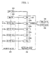
- the assembled battery 400 is a battery that supplies power to the power load 500.
- the assembled battery 400 includes a plurality of battery cells, for example, four battery cells 410a to 410d (hereinafter, generically referred to as battery cells 410).
- the battery cells 410 are connected in series to each other.
- the assembled battery 400 may include a plurality of battery cell groups, each having a plurality of battery cells connected in series to each other, and the battery cell groups may be connected in parallel.
- the battery cell state management system 100 manages the degree of power consumption of each battery cell 410.
- the battery cell state management system 100 includes a plurality of CMUs 200a to 200d (hereinafter, generically referred to as CMUs 200) and a BMU 300.
- the CMU 200 is an example of a battery cell management unit according to the invention.
- the BMU 300 is an example of an assembled battery management unit according to the invention.
- the CMU 200 is a management unit that manages the degree of power consumption of the corresponding battery cell 410.
- the CMUs 200 are provided in one-to-one correspondence with the battery cells 410.
- the CMU 200a is provided so as to correspond to only the battery cell 410a.
- the CMUs 200b to 200d are provided so as to respectively correspond to the battery cells 410b to 410d.
- the CMUs 200 are also provided in one-to-one correspondence with the battery cells 410 in each battery cell group.
- the CMUs 200 are connected to each other through a bus for data communication.
- each of the CMUs 200 is connected in the same order respectively as each of the corresponding battery cells 410 connected to each other.
- the battery cells 410 are connected in series in the order of the battery cell 410a, the battery cell 410b, the battery cell 410c, and the battery cell 410d. Therefore, the CMUs 200 are connected in the order of the CMU 200a, the CMU 200b, the CMU 200c, and the CMU 200d.
- One of the CMUs 200 receives data from another CMU 200 connected thereto on one side, performs a necessary process on the received data, and transmits the data to the other CMU 200 that is connected thereto on the other side.
- the CMU 200b receives data from the CMU 200a, performs a necessary process on the received data, and transmits the data to the CMU 200c.
- the CMU 200b receives data from the CMU 200c, performs a necessary process on the received data, and transmits the data to the CMU 200a.
- only one CMU 200 is connected to the CMU 200 that is connected to the end.
- the CMU 200 connected to the end receives data from another CMU 200, performs a necessary process on the received data, and transmits the data to the CMU 200 that has transmitted the data.
- the CMU 200a connected to the BMU 300 receives data from the BMU 300, performs a necessary process on the received data, and transmits the data to the CMU 200b.
- the CMU 200a receives data from the CMU 200b, performs a necessary process on the received data, and transmits the data to the BMU 300.
- the CMU 200 has a function of monitoring the state of the battery cell 410 that has been managed by the CMU 200.
- the CMU 200 monitors the state of the battery cell 410, such as a battery temperature, an inter-terminal voltage, and a case voltage.
- the CMU 200 In case of an error in the state of the battery cell, the CMU 200 notifies the BMU 300 that an error has occurred.
- the CMU 200 has a function of calculating SOC (State of Charge) in cooperation with the BMU 300 and a function of balancing a voltage of each of the battery cells 410 which is called as "cell balance".
- the BMU 300 is a management unit that manages the degree of power consumption of the assembled battery 400.
- the BMU 300 is connected to any one of the CMUs 200 through the bus for data communication.
- the BMU 300 performs data communication with the CMUs 200 that are connected in series to each other. For example, data is transmitted from the BMU 300 to the CMU 200d through the CMU 200a, the CMU 200b, and the CMU 200c according to this order. In addition, data is transmitted from the CMU 200d to the BMU 300 through the CMU 200c, CMU 200b, and the CMU 200a according to this order.
- the BMU 300 receives data indicating the degree of power consumption of each battery cell 410 (the data is indicating a power consumption state value Y, which will be described below) from each CMU 200, and manages the degree of power consumption of the assembled battery 400.
- the assembled battery 400 includes a plurality of battery cell groups that is connected in parallel, each of BMUs corresponding to the BMU 300 may be provided respectively in each battery cell group, or only one BMU 300 may be provided in the assembled battery 400.
- the power load 500 is a system or an apparatus that is operated by power supplied from the assembled battery 400.
- the power load 500 is, for example, an electric motor that is connected to a wheel.
- examples of the battery system including the assembled battery 400, the battery cell state management system 100, the input device 700, and the output device 800 include an industrial vehicle, such as a forklift, an electric vehicle, a hybrid vehicle, and an electric train.
- the battery system may be a ship or an airplane having an electric motor connected to a propeller.
- the electric motor may drive a peripheral device, such as a wiper, as well as the wheel or the propeller.
- the power load 500 is connected to the BMU 300 through a bus for data communication.
- the power load 500 transmits data for imforming the on/off states of the apparatus or the system, that is operated by the power supplied from the assembled battery 400, to the BMU 300.
- the ammeter 600 is an electric meter that measures an electric current output from the assembled battery 400 to the power load 500.
- the ammeter 600 also measures the current input from a charging apparatus or a power generating apparatus (not shown) to the battery cell 410 when the battery cell 410 is charged.
- the ammeter 600 is connected to the BMU 300 through a bus for data communication.
- the ammeter 600 transmits data indicating the measured current value to the BMU 300.
- the input device 700 is connected to the CMU 200 through a bus for data communication.
- the input device 700 transmits data indicating a command input from the user to the CMU 200.
- the input device 700 receives the command to output information indicating the degree of power consumption of the battery cell 410 that is managed by the CMU 200.
- the input device 700 is connected to the CMU 200a. Therefore, the command received by the input device 700 becomes a command to output information indicating the degree of power consumption of the battery cell 410a that is managed by the CMU 200a. It goes without saying that, when a command to output information indicating the degree of power consumption of the battery cell 410b is issued, the input device 700 is connected to the CMU 200b.
- the input device 700 may be connected to the BMU 300 through a bus for data communication. In this case, the input device 700 receives a command to output information indicating the degree of power consumption of a target battery cell 410 after the target battery cell 410 is designated.
- the battery cells 410 may be individually designated, or sets of a plurality of battery cells 410 may be designated.
- the output device 800 outputs information (power consumption state value Y which will be described below) indicating the degree of power consumption of each battery cell 410 and the connection order of the battery cell, which will be described below.
- Examples of the output device 800 may include a monitor, a printer, or an LED, that is provided in a maintenance device for checking the degree of power consumption of the battery cell 410.
- an instrument panel or a monitor for a car navigation system may be used as the output device 800.
- the output device 800 is connected to the CMU 200 through a bus for data communication.
- the output device 800 receives data from the CMU 200, which indicates the degree of power consumption of the battery cell 410 to be managed by the CMU 200, and outputs information indicating the degree of power consumption represented by the data.
- the output device 800 may be connected to the BMU 300 through a bus for data communication. In this case, the output device 800 receives data indicating the degree of power consumption of the battery cell 410 designated by the input device 700.
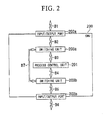
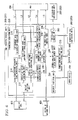
- FIG. 2 is a diagram illustrating an example of the structure of the CMU 200.
- the CMU 200 includes a process control unit 201, input/output ports 202a and 202b (hereinafter, generically referred to as input/output ports 202), and switching units 203a and 203b (hereinafter, generically referred to as switching units 203).
- a process control unit 201 input/output ports 202a and 202b
- switching units 203a and 203b hereinafter, generically referred to as switching units 203.
- the process control unit 201 is a processing unit that performs a process to manage the degree of power consumption of the battery cell 410, which is a management target.
- the process control unit 201 performs data communication with the upstream CMU 200 through the input/output port 202a.
- the input/output port 202a is connected to the upstream CMU 200 through an external bus B1 for data communication.
- the process control unit 201 performs data communication with the downstream CMU 200 through the input/output port 202b.
- the input/output port 202b is connected to the downstream CMU 200 through an external bus B6 for data communication.
- the switching unit 203a is provided between the process control unit 201 and the input/output port 202a.
- the switching unit 203a and the process control unit 201 are connected to each other through an internal bus B3 for data communication.
- the switching unit 203a and the input/output port 202a are connected to each other through an internal bus B2 for data communication.
- the switching unit 203b is provided between the process control unit 201 and the input/output port 202b.
- the switching unit 203b and the process control unit 201 are connected to each other through an internal bus B4 for data communication.
- the switching unit 203b and the input/output port 202b are connected to each other through an internal bus B5 for data communication.
- a bypass that does not pass through the process control unit 201 is provided between the switching unit 203a and the switching unit 203b.
- the bypass is formed by an internal bus B7 for data communication.
- the switching unit 203a and the switching unit 203b work as switches that alternatively select the path of data in the CMU 200 between a path passing through the process control unit 201 via the bus B3 and the bus B4 and a path passing through the bus B7, which is the bypass. It is supposed that the process control unit 201 is normally operated immediately after the battery system is made. Therefore, the switching units 203a and 203b are initially set to select the path of data through the process control unit 201 via the bus B3 and the bus B4. In case that the process control unit 201 is out of order, the switching units 203a and 203b are controlled to select the path of data through the bus B7 as the bypass.
- the CMU 200 and the BMU 300 control the switching unit 203 of the CMU 200, which is a destination of data, to switch the path to the bus B7, which is the bypass.
- the path is switched to the bus B7, which is the bypass, data transmitted from another CMU 200 passes through only the bus B7, which is the bypass, without passing through the process control unit 201 which is out of order.
- the upstream CMU 200 or the BMU 300 controls the switching operation of the switching unit 203a and the switching unit 203b.
- the switching control may be performed by the downstream CMU 200.
- the downstream CMU 200c cannot receive any valid data.
- the switching control unit 290 (which will be described below with reference to FIG. 6 ) of the process control unit 201 of the CMU 200c transmits a switching signal to the upstream bus B1.
- the switching unit 203b of the CMU 200b having the process control unit 201 that is out of order includes a second switching control unit (not shown) that is connected to the switching unit 203a of the CMU 200b and controls the two switching units at the same time.
- the switching unit 203b receives the switching signal transmitted from the CMU 200c
- the second switching control unit switches the path to the bus B7, which is the bypass. In this way, the CMU 200c can receive data transmitted from the BMU 300 or the CMU 200a.
- FIG. 3 is a diagram illustrating an example of the connection structure between the battery cell 410 and the CMU 200.
- a case body 414 of the battery cell 410 includes a temperature measuring circuit 413.
- the temperature measuring circuit 413 includes a sensor that measures the temperature of the battery cell 410.
- the process control unit 201 of the CMU 200 acquires data indicating the temperature value of the battery cell 410 measured by the temperature measuring circuit 413.
- the process control unit 201 of the CMU 200 detects the potential value of a positive terminal 411 with respect to a reference potential.
- the process control unit 201 of the CMU 200 detects the voltage between the positive terminal 411 and a negative terminal 412.
- the case body 414 and the positive terminal 411 are connected to each other with a resistor 430 interposed therebetween in order to obtain a significant potential of the case body 414.
- the process control unit 201 of the CMU 200 may be configured so as to detect the potential value of the case body 414.
- the battery cell 410 is provided with a balance circuit for a voltage balance when there is a voltage variation among the battery cells 410.
- the balance circuit is operated to reduce the voltage of the battery cell 410.
- the balance circuit includes, for example, a switch 450 that switches the on/off of the connection between the positive terminal 411 and the negative terminal 412 with the resistor 440 interposed therebetween.
- the balance circuit turns on or off the switch 450 in response to a control command from the CMU 200.
- the CMU 200 monitors the voltage of the battery cell 410 to be managed and transmits data indicating the voltage value to the BMU 300.
- the BMU 300 compares the values of the battery cells 410 indicated by the data received from each CMU 200. When there is the difference between the voltage values of the battery cells 410, the BMU 300 transmits data for instructing the operation of the balance circuit to the CMU 200 that manages the battery cell 410 with a high voltage.
- the CMU 200 receiving the data transmits data indicating a control command to the balance circuit such that the balance circuit turns on the switch 450. Then, the balance circuit turns on the switch 450 according to the command.
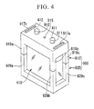
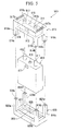
- the battery cell unit 990 has a structure in which the battery cell 410 and the CMU 200 are provided in the cover unit 900.
- the cover unit 900 is made of an insulating material, such as plastic, and can be divided into an upper cover 910 and a lower cover 920.
- the battery cell 410 can be provided between the upper cover 910 and the lower cover 920.
- the upper cover 910 includes a concave portion 918 to which an upper part of the battery cell 410 is fitted.
- Supports 919a to 919d (hereinafter, generically referred to as supports 919) are formed at four corners of the upper cover 910 so as to extend downward.
- Holes 911 and 912 through which the positive terminal 411 and the negative terminal 412 of the battery cell 410 pass when the battery cell 410 is fitted are formed in the upper part of the upper cover 910. In this way, when the battery cells 10 is fitted to the concave portion 918 of the upper cover 910, a portion of the leading end of each of the positive terminal 411 and the negative terminal 412 of the battery cell 410 is exposed to the outside of the case body of the upper cover 910.
- metal contacts 916a and 916b (hereinafter, generically referred to as metal contacts 916) that are electrically connected to the positive terminal 411 and the negative terminal 412 of the battery cell 410 are provided around the holes 911 and 912 of the upper cover 910, respectively.
- Input/output connectors 917a and 917b are formed on the upper surface of the upper cover 910.
- Connectors of a bus cable for example, a cable for the bus B1 or B6 for transmitting or receiving data are connected to the input/output connectors 917a and 917b.
- Connectors at the other end of the cable are connected to the input/output connectors 917 of another cover unit 900.
- the cover units 900 since the cover units 900 are connected to each other by the cable, it is possible to perform data communication between the CMUs 200 provided in the cover units 900.
- the cover units 900 may be connected to each other by the cable. Therefore, it is easy to connect the cover units with the cable.
- Metal terminals 914a to 914d (hereinafter, generically referred to as metal terminals 914) are provided on the leading end surfaces of the supports 919a to 919d of the upper cover 910, respectively.
- the metal terminals 914a to 914d are electrically connected to the metal terminal 913, the metal contacts 916a and 916b, the input/output connectors 917a and 917b, and the balance circuit (not shown). Since the input/output connectors 917a and 917b are connected to the bus cable, they are multi-pin connectors.
- the metal terminal 914 are multi-pin terminals (or multi-pin connectors) capable of transmitting a plurality of electric signals.
- a concave portion 928 to which a lower part of the battery cell 410 is fitted is formed in the lower cover 920.
- Supports 929a to 929d (hereinafter, generically referred to as supports 929) are formed at four corners of the lower cover 920 so as to extend upward.
- the CMU 200 is buried in the bottom 921 of the lower cover 920. The reason is as follows. Since the temperature of the upper part of the battery cell 410 is high, it is preferable that an integrated circuit, such as the CMU that is relatively weak against high temperature, be provided in the lower cover 920 rather than in the upper cover 910.
- the safety valve 415 is provided at the upper part of the battery cell 410. Therefore, when the CMU 200 is provided at the upper part of the battery cell 410, the circuit is out of order during the operation of the safety valve 415, which leaves no failure history.
- the battery cell and the CMU that is in one-to-one correspondence with the battery cell are integrated and carried as the battery cell unit 990. Therefore, when the battery cell is replaced in the battery system of, for example, an electric vehicle into which the assembled battery including a plurality of battery cells is incorporated, it is possible to determine whether each used battery cell to be incorporated is in a good state with low power consumption before it is incorporated into the battery system. That is, it is possible to effectively replace the battery cell.
- the structure using the cover unit 900 having a square shape has been described above, but the shape of the cover unit 900 is not limited to the square shape.
- the cover unit 900 may have various shapes according to the shape of the battery cell 410.
- the cover unit 900 may have a shape capable of accommodating the battery cell 410 having a substantially cylindrical shape. That is, the cover unit 900 may have a substantially cylindrical shape when the upper cover 910 and the lower cover 920 are combined with each other.
- the supports 919 of the upper cover 910 and the supports of the lower cover 920 are formed at the four corners of the upper and lower covers.
- the positions of the supports 919 and 929 are not limited thereto. That is, the supports 919 and 929 may be formed such that the leading ends of the supports 919 and the leading ends of the supports 929 come into contact with each other when the upper cover 910 and the lower cover 920 are combined, or they may be formed at positions that come into contact with the side surface of the battery cell 410.
- the four supports 919 and the four supports 929 are not necessarily formed, but the number of supports 919 may be equal to the number of supports 929.
- FIG. 6 is a block diagram illustrating the functional structure of the CMU 200.
- FIG. 7 is a block diagram illustrating the functional structure of the BMU 300.
- the CMU 200 includes an intrinsic parameter acquiring unit 210, a connection order calculating unit 220, a power consumption state value calculating unit 230, a power consumption state value data storage unit 240, a request receiving unit 250, a power consumption state value data extracting unit 260, a power consumption state value data output unit 270, a balance circuit control unit 280, and a switching control unit 290.
- the intrinsic parameter acquiring unit 210 is a processing unit that acquires parameters related to the battery cell 410 to be managed.
- the intrinsic parameter acquiring unit 210 includes a voltage detecting unit 211, a potential value acquiring unit 212, an inter-terminal voltage value acquiring unit 213, a high-temperature exposure time acquiring unit 214, a low current mode information acquiring unit 215, and a high current mode information acquiring unit 216.
- the voltage detecting unit 211 is a processing unit that detects a voltage value between the positive terminal 411 and the negative terminal 412 of the battery cell 410 to be managed and the potential value of the positive terminal 411 of the battery cell 410 to be managed with respect to the reference potential.
- the voltage detecting unit 211 is connected to the positive terminal 411 of the battery cell 410 to be managed.
- the voltage detecting unit 211 is connected to the negative terminal 412 of the battery cell 410 to be managed.
- the voltage detecting unit 211 is connected to the reference potential (not shown), such as the ground for a signal of the bus that connects the CMUs 200.
- the voltage detecting unit 211 detects the potential of the positive terminal 411 with respect to the reference potential, and transmits data indicating the detected potential value to the potential value acquiring unit 212.
- the voltage detecting unit 211 detects the potential of the positive terminal 411 with respect to the potential of the negative terminal 412, and transmits data indicating the detected potential value as data indicating the inter-terminal voltage value to the inter-terminal voltage value acquiring unit 213.
- the potential value acquiring unit 212 is a processing unit that acquires a value indicating the potential of the positive terminal 411 of the battery cell 410 to be managed with respect to the reference potential.
- the potential value acquiring unit 212 receives the data indicating the potential value from the voltage detecting unit 211 and transmits the data to the connection order calculating unit 220.
- the inter-terminal voltage value acquiring unit 213 is a processing unit that acquires a value indicating the voltage between the positive terminal 411 and the negative terminal 412 of the battery cell 410 to be managed.
- the inter-terminal voltage value acquiring unit 213 receives data indicating the inter-terminal voltage value from the voltage detecting unit 211, and transmits the data to the connection order calculating unit 220.
- the inter-terminal voltage value acquiring unit 213 receives data indicating the connection order of the battery cell 410 to be managed from the connection order calculating unit 220, and transmits the data indicating the connection order and the data indicating the inter-terminal voltage value to the inter-terminal voltage balance determining unit 320 of the BMU 300 through the bus L3.
- the high-temperature exposure time acquiring unit 214 is a processing unit that acquires the time for which the temperature of the battery cell 410 to be managed is equal to or greater than a predetermined value.
- the high-temperature exposure time acquiring unit 214 receives a value indicating the temperature of the battery cell 410 to be managed from the temperature measuring circuit 413 of the battery cell 410 and counts the time for which the temperature is equal to or greater than a predetermined value.
- the high-temperature exposure time acquiring unit 214 transmits data indicating the counted time to the power consumption state value calculating unit 230.
- the time for which the temperature is equal to or greater than the predetermined value is a factor for calculating the power consumption state value Y of the battery cell, which will be described below.
- One or more predetermined values that is, one or more temperature threshold values may be provided, a weight coefficient may be set for each temperature range, data indicating the sum of values obtained by multiplying each time within the temperature range by the coefficients may be transmitted to the power consumption state value calculating unit 230, and the data may be used as a factor for calculating the power consumption state value Y.
- the temporal calculation element is referred to as a temperature deterioration condition number T H .
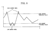
- the low current mode information acquiring unit 215 is a processing unit that acquires information indicating that a current input to the battery cell 410 to be managed and a current output from the battery cell 410 to be managed are equal to or less than a predetermined low current threshold value (see FIG. 8 : hereinafter, referred to as a low current mode).
- the low current mode information acquiring unit 215 receives data indicating the current value measured by the ammeter 600 from a total input/output current amount acquiring unit 311 of a common parameter acquiring unit 310 of the BMU 300 through the bus L1, and counts, for example, the number of times the low current mode is performed.
- the low current mode information acquiring unit 215 transmits data indicating the count value to the power consumption state value calculating unit 230.
- the low current mode information acquiring unit 215 may calculate, for example, the integrated value of the absolute value of a value obtained by subtracting a threshold value from a current value in the low current mode, without counting the number of times the low current mode is performed. This is because the integrated value can represent the damage of the battery more accurately than the number of times the current value is equal to or greater than a predetermined threshold value. In this case, the low current mode information acquiring unit 215 transmits data indicating the calculated value to the power consumption state value calculating unit 230.
- the number of times the low current mode is performed or the integrated value is related to a low current and is a factor for calculating the power consumption state value Y of the battery cell, which will be described below.
- the low current element is referred to as a low current condition number N L .
- the high current mode information acquiring unit 216 is a processing unit that acquires information indicating that a current input to the battery cell 410 to be managed and a current output from the battery cell 410 to be managed are equal to or greater than a predetermined high current threshold value (see FIG. 8 : hereinafter, referred to as a high current mode).
- the high current mode information acquiring unit 216 receives data indicating the current value measured by the ammeter 600 from the total input/output current amount acquiring unit 311 of the common parameter acquiring unit 310 of the BMU 300 through the bus L2, and counts, for example, the number of times the high current mode is performed. Then, the high current mode information acquiring unit 216 transmits data indicating the count value to the power consumption state value calculating unit 230.
- the high current mode information acquiring unit 216 may calculate, for example, the integrated value of the absolute value of a value obtained by subtracting a threshold value from a current value in the high current mode, without counting the number of times the high current mode is performed. Similar to the above, this is because the integrated value can represent the damage of the battery more accurately than the number of times the current value is equal to or greater than a predetermined threshold value. In this case, the high current mode information acquiring unit 216 transmits data indicating the calculated value to the power consumption state value calculating unit 230.
- the number of times the high current mode is performed or the integrated value is related to a high current and is a factor for calculating the power consumption state value Y of the battery cell, which will be described below.
- the high current element is referred to as a high current condition number N H .
- connection order calculating unit 220 calculates the connection order of the battery cell 410 to be managed on the basis of the values indicated by the received data, and transmits data indicating the calculated connection order to the inter-terminal voltage value acquiring unit 213 and the power consumption state value calculating unit 230.
- the calculation of the connection order will be described below.
- the power consumption state value calculating unit 230 is a processing unit that calculates a value indicating the degree of power consumption of the battery cell 410 to be managed.
- the power consumption state value calculating unit 230 receives data indicating the temperature deterioration condition number T H of the battery cell 410 to be monitored from the high-temperature exposure time acquiring unit 214.
- the power consumption state value calculating unit 230 receives data indicating the low current condition number N L from the low current mode information acquiring unit 215.
- the power consumption state value calculating unit 230 receives data indicating the high current condition number N H from the high current mode information acquiring unit 216.
- the power consumption state value calculating unit 230 receives the integrated value of the absolute value of the current value measured by the ammeter 600, that is, data indicating a total input/output current amount Q from the total input/output current amount acquiring unit 311 of the BMU 300 through the bus L4. In addition, the power consumption state value calculating unit 230 receives the count value of the start time of the power load 500 after the power load 500 receives power supplied from the assembled battery 400, that is, data indicating a start time T from a start time acquiring unit 312 of the BMU 300. Then, the power consumption state value calculating unit 230 calculates a value indicating the degree of power consumption of the battery cell 410 to be managed, that is, the power consumption state value Y, on the basis of the data. The calculation of the power consumption state value Y will be described below.
- the power consumption state value calculating unit 230 receives data indicating the connection order of the battery cell 410 to be managed from the connection order calculating unit 220. Then, the power consumption state value calculating unit 230 stores the data indicating the power consumption state value Y of the battery cell 410 to be managed and the data indicating the connection order of the battery cell 410 to be managed in the power consumption state value data storage unit 240 so as to be associated with each other.
- the request receiving unit 250 is a processing unit that receives a request to output data indicating the power consumption state value Y of the battery cell 410 to be managed from the user.
- the request receiving unit 250 receives data indicating the request to output data indicating the power consumption state value Y of the battery cell 410 to be managed from the user from the input device 700, and transmits data indicating a command to extract the data indicating the power consumption state value Y of the battery cell 410 to be managed to the power consumption state value data extracting unit 260.
- the power consumption state value data extracting unit 260 is a processing unit that extracts the data indicating the power consumption state value Y of the battery cell 410 to be managed from the power consumption state value data storage unit 240.
- the power consumption state value data extracting unit 260 receives data indicating a command to extract the data indicating the power consumption state value Y of the battery cell 410 to be managed from the request receiving unit 250, extracts the data indicating the power consumption state value Y of the battery cell 410 to be managed from the power consumption state value data storage unit 240, and transmits the extracted data to the power consumption state value data output unit 270.
- the switching control unit 290 is a processing unit that controls the operation of the switching unit 203 of another CMU 200 connected to the CMU 200 to which the switching control unit 290 belongs. Since the CMU 200 is connected in series to another CMU 200, the CMU 200 sequentially transmits or receives the command signal from the BMU or data that is output from a memory, such as the power consumption state value data storage unit 240, or the parameter acquiring unit of the CMU in correspondence with the command signal. When receiving data, the CMU or the BMU transmits a response signal indicating that the data has been received.
- the switching control unit 290 When there is no response within a predetermined period of time after the CMU 200 to which the switching control unit 290 belongs transmits data to another CMU 200 or when measured data to be transmitted is not transmitted within a predetermined period of time, the switching control unit 290 operates the switching unit 203 of another CMU 200 that does not transmit a response or data to switch the path of data in another CMU 200 that does not transmit a response from a general internal bus to an internal bus for a bypass.
- the inter-terminal voltage balance determining unit 320 is a processing unit that determines whether the balance of the inter-terminal voltage of each battery cell 410 is maintained.
- the inter-terminal voltage balance determining unit 320 receives data indicating the inter-terminal voltage value of the battery cell 410 to be managed together with data indicating the connection order of the battery cell 410 from the inter-terminal voltage value acquiring unit 213 of each CMU 200 through the bus L3.
- the inter-termlnal voltage balance determining unit 320 specifies the battery cell 410 with a high inter-terminal voltage value and transmits data indicating the connection order of the battery cell 410 to the balance circuit control command unit 330.
- the balance circuit control command unit 330 is a processing unit that instructs the CMU 200 which manages the battery cell 410 with an inter-terminal voltage value higher than that of other battery cells to operate the balance circuit provided in the battery cell 410 to be managed.
- the balance circuit control command unit 330 receives data indicating the connection order of the battery cell 410 with a high inter-terminal voltage value from the inter-terminal voltage balance determining unit 320 and transmits data indicating a command to operate the balance circuit provided in the battery cell 410 to be managed to the balance circuit control unit 280 of the CMU 200 which manages the battery cell 410 through the bus L5.
- FIG. 9 is a diagram illustrating an example of the flow of a process of managing the power consumption of the battery cell 410.
- the intrinsic parameter acquiring unit 210 of the CMU 200 and the common parameter acquiring unit 310 of the BMU 300 acquire parameters, which are power consumption factors of the battery cell 410 (S101). Specifically, the intrinsic parameter acquiring unit 210 and the common parameter acquiring unit 310 of the BMU 300 acquire data indicating the total input/output current amount Q, the start time T, the low current condition number N L , the high current condition number N H , and the temperature deterioration condition number T H .
- the power consumption state value calculating unit 230 of the CMU 200 calculates the power consumption state value Y, which is a value indicating the degree of power consumption of the battery cell 410, for each battery cell 410 on the basis of the parameters acquired by the intrinsic parameter acquiring unit 210 of the CMU 200 and the common parameter acquiring unit 310 of the BMU 300 (S102). Specifically, the power consumption state value calculating unit 230 multiplies each parameter by a predetermined weighting coefficient and adds the calculated values. In this embodiment, for example, the parameter that causes the power consumption of the battery cell 410 to be reduced at a high rate when the acquired value of the parameter increases is multiplied by a large weighting coefficient.
- the weighting coefficient is a predetermined constant and is stored in the power consumption state value calculating unit 230.
- the power consumption state value Y of the battery cell 410 is calculated on the basis of five parameters. However, all of the parameters are not necessarily required. For example, as another embodiment, some of the parameters may be used to calculate the power consumption state value of the battery cell 410. When two or more parameters are used, it is possible to calculate the power consumption state value Y considering various points of view. For example, it is possible to increase the degree of importance of the parameters as a reference value when a used battery cell is reused.
- the case voltage of the battery cell 410 may be added as a parameter.
- the case body 414 When the positive terminal 411 and the case body 414 are connected to each other with a resistor interposed therebetween such that the case body 414 is not melted, the case body 414 is pulled up to positive potential.
- the case voltage when a minute hole is formed in the case body 414 and liquid leaks through the hole, the case voltage varies. Therefore, the case voltage is useful as a factor for calculating the power consumption state value Y.
- the following process is performed in order to check the power consumption state of each battery cell 410.
- the request receiving unit 250 receives a request to output the power consumption state value data stored in the power consumption state value data storage unit 240 from the user (S104). Specifically, the request receiving unit 250 receives the request from the user through the external input device 700. For example, the user may input a desired power consumption state value and require the output of information of the battery cell with a power consumption state value larger than the desired power consumption state value, In addition, the user may input the connection order, which will be described below, and require the output of the power consumption state value data stored in the CMU corresponding to the battery cell in a desired connection order.
- the power consumption state value data extracting unit 260 of the CMU 200 extracts the power consumption state value data from the power consumption state value data storage unit 240 on the basis of the request received by the request receiving unit 250 (S105). Then, the power consumption state value data output unit 270 of the CMU 200 outputs the power consumption state value data extracted by the power consumption state value data extracting unit 260 to the external output device 800 (S106). Data indicating the output power consumption state value Y may be the power consumption state value Y. Further, the ratio of the power consumption, state value of the current battery cell 410 to the power consumption state value of the unused battery cell 410 may be output as the degree of power consumption of the battery cell 410 in order to make it easy to objectively determine the power consumption state. When the power consumption state value data of a plurality of battery cells 410 is output, a list of the power consumption state value data of the battery cells 410 or a graph illustrating the power consumption state value data of the battery cells 410 may be output.
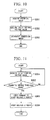
- FIG. 10 is a diagram illustrating an example of the flow of a process of managing the connection order of the battery cells 410.
- the potential value acquiring unit 212 of the CMU 200 acquires the potential value of the positive terminal 411 of the battery cell 410 with respect to the reference potential in the initial state in which the assembled battery 400 is incorporated into the system, for example, when the assembled battery 400 is incorporated into an electric vehicle as the system and starts up at the beginning (S201). Specifically, the potential value acquiring unit 212 acquires the potential value of the positive terminal 411 of the battery cell 410 to be monitored with respect to the reference potential from the voltage detecting unit 211.
- the inter-terminal voltage value acquiring unit 213 of the CMU 200 acquires the inter-terminal voltage value of the battery cell 410 (S202). Specifically, the inter-terminal voltage value acquiring unit 213 acquires the inter-terminal voltage value of the battery cell 410 to be monitored from the voltage detecting circuit 420 provided in the battery cell 410 to be monitored.
- connection order calculating unit 220 of the CMU 200 calculates a connection order value indicating the connection order of the battery cell 410 to be monitored on the basis of the potential value acquired by the potential value acquiring unit 212 and the inter-terminal voltage value acquired by the inter-terminal voltage value acquiring unit 213 (S203).
- the battery cells 410 of the assembled battery 400 are connected in series.
- the connection order value of the battery cell 410 calculated by the connection order calculating unit 220 indicates the figure for the position of the battery cell 410 to be monitored from the reference potential among the plurality of battery cells 410 connected in series.
- nv (potential value)/v (inter-terminal voltage) n is established, and it is determined that the battery cell 410 is disposed in the n-th place from the reference potential among the plurality of battery cells 410 connected in series.
- a value obtained by dividing the potential of the positive terminal by the inter-terminal voltage between the positive and negative terminals is not an integer, for example, the value is rounded to the next whole number and the position of the battery cell may be determined.
- the denominator of the division is the inter-terminal voltage of each battery cell, but it may be the average value of the inter-terminal voltages of the battery cells that are connected in series in the assembled battery. In this case, it is possible to round off variations in the inter-termittal voltage of each of the battery cells in the assembled battery and accurately calculate the connection order of the battery cell.
- each CMU 200 can also determine its own connection order in response to a request from the user, except the CMU that is out of order.
- connection order calculated by each CMU 200 that is in a normal state is constant regardless of whether the process control unit 201 of the CMU 200 is out of order.
- the connection order of each of a plurality of battery cells 410 which is connected in series from the reference potential is stored in the power consumption state value data storage unit so as to be associated with the power consumption state value data of each battery cell 410. Therefore, for example, it is possible to easily identify a battery cell among the battery cells 410 corresponding to the information of the power consumption state value data by recognizing only the information.
- FIG. 11 is a diagram illustrating an example of the flow of a process of starting the balance circuit provided in the battery cell 410.
- the inter-terminal voltage value acquiring unit 213 of the CMU 200 acquires the inter-terminal voltage value of the battery cell 410 to be managed (S301). Then, the inter-terminal voltage value acquiring unit 213 periodically transmits data indicating the acquired inter-terminal voltage value and data indicating the connection order of the battery cell 410 to be managed to the inter-terminal voltage balance determining unit 320 of the BMU 300.
- the inter-terminal voltage balance determining unit 320 of the BMU 300 determines whether the inter-terminal voltage of each battery cell 410 is balanced (S302). For example, the inter-terminal voltage balance determining unit 320 compares the inter-terminal voltage values of the battery cells 410 indicated by data received from the inter-terminal voltage acquiring unit 213 of each CMU 200. When there is the difference between the inter-terminal voltage values, the inter-terminal voltage balance determining unit 320 specifies the battery cell 410 with a high inter-terminal voltage value. In this case, when the difference is less than a predetermined allowable value, the inter-terminal voltage balance determining unit 320 determines that the balance is maintained. Then, the inter-terminal voltage balance determining unit 320 transmits data indicating the connection order of the battery cell 410 to the balance circuit control command unit 330,
- the balance circuit control command unit 330 of the BMU 300 receives data indicating the connection order of the battery cell 410 with a high inter-terminal voltage value and instructs the switching control unit 290 of the CMU 200 that monitors the battery cell 410 to start the balance circuit (S303).
- the balance circuit control unit 280 of the CMU 200 that receives the command to start the balance circuit from the balance circuit control command unit 330 of the BMU 300 starts the balance circuit provided in the battery cell 410 to be managed (S304). Specifically, the balance circuit control unit 280 turns on the switch 450 of the balance circuit which is provided in the battery cell 410 to be managed. In this way, after the balance circuit provided in the battery cell 410 to be managed starts, the inter-terminal voltage value acquiring unit 213 of the CMU 200 resumes acquiring the inter-terminal voltage value of the battery cell 410 to be managed.
- the power consumption state value calculating unit 230 of each CMU 200 calculates a value indicating the degree of power consumption of the battery cell 41 to be managed.
- the BMU 300 may calculate the value.
- each CMU 200 transmits data required to calculate the value indicating the degree of power consumption of the battery cell 410 to be managed to the BMU 300.
- each CMU 200 receives the data of the value indicating the degree of power consumption of the battery cell 410 to be managed from the BMU 300 and stores the received data in the power consumption state value data storage unit 240.
- the assembled battery including a plurality of battery cells connected in series, it is possible to acquire each power consumption parameter from each of the battery cells and manage data indicting the power consumption state of each battery cell calculated on the basis of each parameter.
- the system of the invention when the assembled battery is reused or maintained, it is possible to easily check the power consumption state of each battery cell and select the reuse or discard of each battery cell,
Landscapes
- Engineering & Computer Science (AREA)
- Chemical & Material Sciences (AREA)
- Chemical Kinetics & Catalysis (AREA)
- Electrochemistry (AREA)
- General Chemical & Material Sciences (AREA)
- Manufacturing & Machinery (AREA)
- Sustainable Energy (AREA)
- Sustainable Development (AREA)
- Life Sciences & Earth Sciences (AREA)
- Power Engineering (AREA)
- Transportation (AREA)
- Mechanical Engineering (AREA)
- Microelectronics & Electronic Packaging (AREA)
- Secondary Cells (AREA)
- Charge And Discharge Circuits For Batteries Or The Like (AREA)
- Tests Of Electric Status Of Batteries (AREA)
- Electric Propulsion And Braking For Vehicles (AREA)
- Remote Monitoring And Control Of Power-Distribution Networks (AREA)
Applications Claiming Priority (1)
| Application Number | Priority Date | Filing Date | Title |
|---|---|---|---|
| JP2009216956A JP5010657B2 (ja) | 2009-09-18 | 2009-09-18 | 電池システム |
Publications (2)
| Publication Number | Publication Date |
|---|---|
| EP2299518A2 true EP2299518A2 (fr) | 2011-03-23 |
| EP2299518A3 EP2299518A3 (fr) | 2011-10-26 |
Family
ID=43431081
Family Applications (1)
| Application Number | Title | Priority Date | Filing Date |
|---|---|---|---|
| EP10176788A Withdrawn EP2299518A3 (fr) | 2009-09-18 | 2010-09-15 | Système de batteries |
Country Status (3)
| Country | Link |
|---|---|
| US (1) | US8566049B2 (fr) |
| EP (1) | EP2299518A3 (fr) |
| JP (1) | JP5010657B2 (fr) |
Cited By (5)
| Publication number | Priority date | Publication date | Assignee | Title |
|---|---|---|---|---|
| US20110071781A1 (en) * | 2009-09-18 | 2011-03-24 | Mitsubishi Heavy Industries, Ltd. | Battery system |
| WO2012178205A3 (fr) * | 2011-06-24 | 2013-05-10 | Mark Olsson | Appareil, systèmes et procédés de bloc de batteries modulaire |
| EP2724391A2 (fr) * | 2011-06-24 | 2014-04-30 | Mark Olsson | Appareil, systèmes et procédés de bloc de batteries modulaire |
| US11171369B1 (en) | 2011-06-24 | 2021-11-09 | SeeScan, Inc. | Modular battery pack apparatus, systems, and methods |
| US11476539B1 (en) | 2012-06-24 | 2022-10-18 | SeeScan, Inc. | Modular battery pack apparatus, systems, and methods including viral data and/or code transfer |
Families Citing this family (12)
| Publication number | Priority date | Publication date | Assignee | Title |
|---|---|---|---|---|
| IT1402010B1 (it) * | 2010-10-08 | 2013-08-28 | St Microelectronics Srl | Dispositivo modulare per la protezione ed il monitoraggio di una batteria. |
| CN102508167B (zh) * | 2011-10-25 | 2014-08-06 | 上海交通大学 | 一种电池管理系统自动测试、自动标定参数的装置和方法 |
| JP5733275B2 (ja) * | 2012-07-13 | 2015-06-10 | トヨタ自動車株式会社 | 組電池の制御装置及び組電池の再利用判定方法 |
| US9172259B2 (en) * | 2012-11-29 | 2015-10-27 | Samsung Sdi Co., Ltd. | Apparatus for managing battery, and energy storage system |
| CN103105522B (zh) * | 2013-03-07 | 2015-01-14 | 上海电气钠硫储能技术有限公司 | 一种用于储能钠硫电池模块电压检测的采集线布线结构 |
| WO2015152878A1 (fr) * | 2014-03-31 | 2015-10-08 | Hewlett-Packard Development Company, L. P. | Réguler des états de processeur |
| JP6413311B2 (ja) | 2014-04-11 | 2018-10-31 | 株式会社村田製作所 | 蓄電装置、制御方法、制御装置、蓄電システム、電動車両および電子機器 |
| CN109591625A (zh) * | 2018-12-07 | 2019-04-09 | 江西洪都航空工业集团有限责任公司 | 一种无人车的冗余电源供电控制方法 |
| CN110103772B (zh) * | 2019-05-15 | 2022-05-27 | 江苏绿城信息技术有限公司 | 一种电动汽车储能装置的能源监控管理系统及其管理方法 |
| US12103427B2 (en) * | 2019-10-17 | 2024-10-01 | Samsung Sdi Co., Ltd. | Method for determining the support of energy content and power of a battery |
| CN113829931B (zh) * | 2020-06-24 | 2023-07-11 | 比亚迪股份有限公司 | 一种列车充电控制方法、装置及列车 |
| KR20220057368A (ko) * | 2020-10-29 | 2022-05-09 | 주식회사 엘지에너지솔루션 | 배터리 관리 장치 및 방법, 배터리 관리 시스템 |
Citations (2)
| Publication number | Priority date | Publication date | Assignee | Title |
|---|---|---|---|---|
| JP2003032907A (ja) | 2001-07-12 | 2003-01-31 | Denso Corp | 充電状態検出装置 |
| US20060061327A1 (en) * | 2004-05-19 | 2006-03-23 | Ko-Chen Shen | Battery with embedded circuits |
Family Cites Families (21)
| Publication number | Priority date | Publication date | Assignee | Title |
|---|---|---|---|---|
| US5115182A (en) * | 1990-04-23 | 1992-05-19 | Motorola, Inc. | Battery charging controller for a battery powered device and method for using the same |
| FR2731111B1 (fr) | 1995-02-23 | 1997-05-23 | Texas Instruments France | Dispositif de protection d'elements rechargeables et transistor mosfet equipant ce dispositif |
| JP3649296B2 (ja) * | 1995-05-12 | 2005-05-18 | ソニー株式会社 | バッテリパックおよび電子機器 |
| US6094053A (en) | 1995-11-06 | 2000-07-25 | Ford Global Technologies, Inc. | Method and apparatus for identifying electronic circuits in a distributed electronic system |
| US6133709A (en) * | 1997-01-21 | 2000-10-17 | Metrixx Limited | Signalling system |
| US6104967A (en) * | 1997-07-25 | 2000-08-15 | 3M Innovative Properties Company | Fault-tolerant battery system employing intra-battery network architecture |
| JP3522162B2 (ja) * | 1999-08-05 | 2004-04-26 | セイコーインスツルメンツ株式会社 | バッテリー装置 |
| JP3807965B2 (ja) * | 2001-09-19 | 2006-08-09 | インターナショナル・ビジネス・マシーンズ・コーポレーション | インテリジェント電池、電気機器、コンピュータ装置及び電池の劣化度を求める方法 |
| US6774602B2 (en) * | 2002-06-14 | 2004-08-10 | Delphi Technologies, Inc. | Apparatus and method for providing temporary power |
| JP2005037230A (ja) * | 2003-07-14 | 2005-02-10 | Toyota Motor Corp | 電池劣化検出装置および方法 |
| JP4806558B2 (ja) * | 2005-10-18 | 2011-11-02 | プライムアースEvエナジー株式会社 | 二次電池用の制御装置及び二次電池の劣化判定方法 |
| EP1941289B1 (fr) * | 2005-10-28 | 2010-12-22 | TEMIC Automotive Electric Motors GmbH | Procede et dispositif pour determiner l'etat de vieillissement d'un accumulateur |
| JP4890977B2 (ja) * | 2006-07-04 | 2012-03-07 | 富士重工業株式会社 | バッテリの劣化演算装置 |
| GB0624858D0 (en) * | 2006-12-13 | 2007-01-24 | Ami Semiconductor Belgium Bvba | Battery Monitoring |
| JP5517398B2 (ja) | 2007-03-15 | 2014-06-11 | 三菱重工業株式会社 | 蓄電システム |
| DE102007028928A1 (de) * | 2007-06-22 | 2009-01-02 | Siemens Ag | Slavegerät für Reihenschaltung und Verfahren zum Ermitteln der Position von Slavengeräten in einer Reihenschaltung |
| US7847436B2 (en) * | 2007-10-17 | 2010-12-07 | Edwin Arthur Blackmond | Modular power supply |
| US7956579B2 (en) * | 2007-12-19 | 2011-06-07 | International Business Machines Corporation | Battery charge management system for charging a battery bank that includes a plurality of batteries |
| JP5560557B2 (ja) * | 2008-02-27 | 2014-07-30 | 日産自動車株式会社 | 組電池の制御装置 |
| JP5561916B2 (ja) * | 2008-07-11 | 2014-07-30 | ミツミ電機株式会社 | 電池状態監視装置 |
| JP5010657B2 (ja) * | 2009-09-18 | 2012-08-29 | 三菱重工業株式会社 | 電池システム |
-
2009
- 2009-09-18 JP JP2009216956A patent/JP5010657B2/ja not_active Expired - Fee Related
-
2010
- 2010-09-15 US US12/882,704 patent/US8566049B2/en active Active
- 2010-09-15 EP EP10176788A patent/EP2299518A3/fr not_active Withdrawn
Patent Citations (2)
| Publication number | Priority date | Publication date | Assignee | Title |
|---|---|---|---|---|
| JP2003032907A (ja) | 2001-07-12 | 2003-01-31 | Denso Corp | 充電状態検出装置 |
| US20060061327A1 (en) * | 2004-05-19 | 2006-03-23 | Ko-Chen Shen | Battery with embedded circuits |
Cited By (7)
| Publication number | Priority date | Publication date | Assignee | Title |
|---|---|---|---|---|
| US20110071781A1 (en) * | 2009-09-18 | 2011-03-24 | Mitsubishi Heavy Industries, Ltd. | Battery system |
| US8566049B2 (en) * | 2009-09-18 | 2013-10-22 | Mitsubishi Heavy Industries, Ltd. | Battery system |
| WO2012178205A3 (fr) * | 2011-06-24 | 2013-05-10 | Mark Olsson | Appareil, systèmes et procédés de bloc de batteries modulaire |
| EP2724391A2 (fr) * | 2011-06-24 | 2014-04-30 | Mark Olsson | Appareil, systèmes et procédés de bloc de batteries modulaire |
| US11171369B1 (en) | 2011-06-24 | 2021-11-09 | SeeScan, Inc. | Modular battery pack apparatus, systems, and methods |
| EP2724391B1 (fr) * | 2011-06-24 | 2025-10-29 | SeeScan, Inc. | Appareil, systèmes et procédés de bloc de batteries modulaire |
| US11476539B1 (en) | 2012-06-24 | 2022-10-18 | SeeScan, Inc. | Modular battery pack apparatus, systems, and methods including viral data and/or code transfer |
Also Published As
| Publication number | Publication date |
|---|---|
| JP5010657B2 (ja) | 2012-08-29 |
| EP2299518A3 (fr) | 2011-10-26 |
| JP2011064627A (ja) | 2011-03-31 |
| US20110071781A1 (en) | 2011-03-24 |
| US8566049B2 (en) | 2013-10-22 |
Similar Documents
| Publication | Publication Date | Title |
|---|---|---|
| US8566049B2 (en) | Battery system | |
| KR101323511B1 (ko) | 전지 팩 및 전지 제어 시스템 | |
| JP5733275B2 (ja) | 組電池の制御装置及び組電池の再利用判定方法 | |
| EP2695762B1 (fr) | Appareil de stockage électrique et appareil de commutation de trajet de puissance | |
| JP4572850B2 (ja) | 電源制御装置 | |
| JP5753764B2 (ja) | 電池システム監視装置およびこれを備えた蓄電装置 | |
| EP2516234B1 (fr) | Appareil de gestion de batterie d'une batterie haute tension pour véhicule hybride | |
| JP4823345B2 (ja) | 電池システム | |
| KR101663579B1 (ko) | 배터리 모니터링 장치 및 이를 이용한 배터리 모니터링 시스템 | |
| EP2770606A1 (fr) | Dispositif de surveillance d'un système accumulateur et dispositif de stockage de charge équipé de celui-ci | |
| EP2348599A1 (fr) | Système de gestion de batterie et son procédé de commande | |
| KR101545306B1 (ko) | 에너지를 재사용하는 배터리 밸런싱 시스템 및 배터리 밸런싱 방법 | |
| EP2161812A1 (fr) | Systeme d'alimentation electrique, et procede de commande d'alimentation electrique et programme de commande d'alimentation electrique utilise dans le systeme d'alimentation electrique | |
| EP1983601A1 (fr) | Bloc de batteries | |
| JP4825733B2 (ja) | 組電池用電池寿命計測システム | |
| KR20120073520A (ko) | 배터리 관리 시스템 및 상기 배터리 관리 시스템을 이용하는 배터리 진단 시스템 | |
| KR20130034618A (ko) | 차량용 전원 장치와 이 전원 장치를 구비하는 차량 | |
| JP2009286292A (ja) | 車両用の電源装置 | |
| CN103827685A (zh) | 用于确定蓄电池单池的充电状态的蓄电池管理系统和方法、具有蓄电池管理系统的蓄电池和机动车 | |
| US11411259B2 (en) | Battery control unit | |
| KR102045047B1 (ko) | 배터리 모듈의 soh 불균형을 고려한 최대용량 충전장치 및 그 제어방법 | |
| GB2467231A (en) | High voltage battery controller with isolation | |
| JP6251136B2 (ja) | 電池システム監視装置およびこれを備えた蓄電装置 | |
| US8711534B2 (en) | Battery power management system and method | |
| CN113924708A (zh) | 用于运行电能量存储器的方法、电能量存储器以及设备 |
Legal Events
| Date | Code | Title | Description |
|---|---|---|---|
| PUAI | Public reference made under article 153(3) epc to a published international application that has entered the european phase |
Free format text: ORIGINAL CODE: 0009012 |
|
| AK | Designated contracting states |
Kind code of ref document: A2 Designated state(s): AL AT BE BG CH CY CZ DE DK EE ES FI FR GB GR HR HU IE IS IT LI LT LU LV MC MK MT NL NO PL PT RO SE SI SK SM TR |
|
| AX | Request for extension of the european patent |
Extension state: BA ME RS |
|
| PUAL | Search report despatched |
Free format text: ORIGINAL CODE: 0009013 |
|
| AK | Designated contracting states |
Kind code of ref document: A3 Designated state(s): AL AT BE BG CH CY CZ DE DK EE ES FI FR GB GR HR HU IE IS IT LI LT LU LV MC MK MT NL NO PL PT RO SE SI SK SM TR |
|
| AX | Request for extension of the european patent |
Extension state: BA ME RS |
|
| RIC1 | Information provided on ipc code assigned before grant |
Ipc: H01M 2/02 20060101ALN20110922BHEP Ipc: H01M 10/48 20060101ALI20110922BHEP Ipc: H01M 10/42 20060101ALI20110922BHEP Ipc: H01M 2/12 20060101ALI20110922BHEP Ipc: H01M 2/10 20060101AFI20110922BHEP |
|
| 17P | Request for examination filed |
Effective date: 20120209 |
|
| 17Q | First examination report despatched |
Effective date: 20130531 |
|
| RIC1 | Information provided on ipc code assigned before grant |
Ipc: H01M 10/60 20140101ALN20150610BHEP Ipc: B60L 11/18 20060101ALI20150610BHEP Ipc: H01M 10/42 20060101ALI20150610BHEP Ipc: H01M 2/12 20060101ALN20150610BHEP Ipc: H01M 2/02 20060101ALN20150610BHEP Ipc: G01R 31/36 20060101ALI20150610BHEP Ipc: H01M 2/10 20060101AFI20150610BHEP Ipc: H01M 10/48 20060101ALI20150610BHEP |
|
| GRAP | Despatch of communication of intention to grant a patent |
Free format text: ORIGINAL CODE: EPIDOSNIGR1 |
|
| INTG | Intention to grant announced |
Effective date: 20150717 |
|
| STAA | Information on the status of an ep patent application or granted ep patent |
Free format text: STATUS: THE APPLICATION IS DEEMED TO BE WITHDRAWN |
|
| 18D | Application deemed to be withdrawn |
Effective date: 20151128 |