EP2299558A1 - Elektrische drehmaschine des permanentmagnettyps - Google Patents
Elektrische drehmaschine des permanentmagnettyps Download PDFInfo
- Publication number
- EP2299558A1 EP2299558A1 EP09766455A EP09766455A EP2299558A1 EP 2299558 A1 EP2299558 A1 EP 2299558A1 EP 09766455 A EP09766455 A EP 09766455A EP 09766455 A EP09766455 A EP 09766455A EP 2299558 A1 EP2299558 A1 EP 2299558A1
- Authority
- EP
- European Patent Office
- Prior art keywords
- magnet
- current
- short circuit
- permanent magnet
- magnetic
- Prior art date
- Legal status (The legal status is an assumption and is not a legal conclusion. Google has not performed a legal analysis and makes no representation as to the accuracy of the status listed.)
- Granted
Links
Images




Classifications
-
- H—ELECTRICITY
- H02—GENERATION; CONVERSION OR DISTRIBUTION OF ELECTRIC POWER
- H02K—DYNAMO-ELECTRIC MACHINES
- H02K1/00—Details of the magnetic circuit
- H02K1/06—Details of the magnetic circuit characterised by the shape, form or construction
- H02K1/22—Rotating parts of the magnetic circuit
- H02K1/27—Rotor cores with permanent magnets
- H02K1/2706—Inner rotors
- H02K1/272—Inner rotors the magnetisation axis of the magnets being perpendicular to the rotor axis
- H02K1/274—Inner rotors the magnetisation axis of the magnets being perpendicular to the rotor axis the rotor consisting of two or more circumferentially positioned magnets
- H02K1/2753—Inner rotors the magnetisation axis of the magnets being perpendicular to the rotor axis the rotor consisting of two or more circumferentially positioned magnets the rotor consisting of magnets or groups of magnets arranged with alternating polarity
- H02K1/276—Magnets embedded in the magnetic core, e.g. interior permanent magnets [IPM]
- H02K1/2766—Magnets embedded in the magnetic core, e.g. interior permanent magnets [IPM] having a flux concentration effect
-
- H—ELECTRICITY
- H02—GENERATION; CONVERSION OR DISTRIBUTION OF ELECTRIC POWER
- H02K—DYNAMO-ELECTRIC MACHINES
- H02K21/00—Synchronous motors having permanent magnets; Synchronous generators having permanent magnets
- H02K21/02—Details
- H02K21/04—Windings on magnets for additional excitation ; Windings and magnets for additional excitation
-
- H—ELECTRICITY
- H02—GENERATION; CONVERSION OR DISTRIBUTION OF ELECTRIC POWER
- H02K—DYNAMO-ELECTRIC MACHINES
- H02K21/00—Synchronous motors having permanent magnets; Synchronous generators having permanent magnets
- H02K21/02—Details
- H02K21/021—Means for mechanical adjustment of the excitation flux
- H02K21/028—Means for mechanical adjustment of the excitation flux by modifying the magnetic circuit within the field or the armature, e.g. by using shunts, by adjusting the magnets position, by vectorial combination of field or armature sections
Definitions
- This invention relates to a permanent magnet electric motor in which two or more types of permanent magnets are engaged and the magnetic flux of at least one of the permanent magnets is changed quantitatively and irreversibly so that a variable speed operation is achieved over a wide range of from a low speed to a high speed.
- this invention relates to a permanent magnet electric motor in which a short circuited coil or conductive plate is located in a rotor core such that the magnetic flux of at least one permanent magnet can be changed quantitatively and irreversibly without being restrained by the influence of the magnetic flux of another permanent magnet.
- permanent magnet electric motors are broadly classified into two categories, that is, “surface permanent magnet motor” in which a permanent magnet is attached on the outer part of a rotor core, and “interior permanent magnet motor” in which a permanent magnet is embedded in a rotor core.
- surface permanent magnet motor in which a permanent magnet is attached on the outer part of a rotor core
- interior permanent magnet motor in which a permanent magnet is embedded in a rotor core.
- the “interior permanent magnet motor” is suitable for use as a variable speed drive motor.
- a permanent magnet electric motor In a permanent magnet electric motor, the flux linkage of a permanent magnet is generated constantly and uniformly, as a result, an induced voltage due to the permanent magnet increases in proportion to the rotational speed. Consequently, during a variable speed operation from a low speed to a high speed, a high speed rotation causes a very high induced voltage (counter electromotive voltage) due to the permanent magnet. If the induced voltage due to the permanent magnet is applied to an electronic component of an inverter and increases up two equal to or more than the withstand voltage thereof, the electronic component results in dielectric breakdown.
- a design is considered, in which the magnetic flux of a permanent magnet is reduced such that an induced voltage due to a permanent magnet is equal to or less than the withstand voltage of an electronic component of an inverter, but this design causes a reduction of output and efficiency in a low speed range of the permanent magnet electric motor.
- lux weakening control which is described in various documents, has come to be applied to a method for enlarging the variable speed range.
- the total flux linkage quantity of an armature coil is determined from the magnetic flux due to a d-axis current and the magnetic flux due to a permanent magnet thereof.
- a magnetic flux is generated by a minus d-axis current, and this flux due to the minus d-axis current causes reduction of the total flux linkage quantity.
- a permanent magnet with a high coercivity is adopted such that a working point of a magnetic characteristic (B-H characteristic) may change in the reversible range. Consequently, an NdFeB magnet with a high coercivity is applied to that of a permanent magnet electric motor such that the permanent magnet is irreversibly demagnetized by a demagnetizing field under the "flux weakening control”.
- the flux due to the minus d-axis current causes reduction of the flux linkage quantity, as a result, the reduced quantity of flux linkage generates a voltage to spare in relation to the upper limit voltage.
- An electric current to be a torque component increases, as a result, the output of a high speed range increases.
- the rotational speed increases in proportion to the voltage to spare, and this enlarges the range of the variable speed operation.
- an "interior permanent magnet motor” When an “interior permanent magnet motor” is applied to a motor for driving a hybrid car, the motor is brought around at the state of only engine drive. In a middle and high speed rotation, an induced voltage of the motor due to a permanent magnet rises, for restraining the induced voltage to be equal to or less than the power supply voltage, a minus d-axis current is caused to flow constantly by the "flux weakening control". In this state, the motor generates only loss, as a result, an overall operating efficiency deteriorates.
- Patent Document 1 and Patent Document 2 a technique is described, which arranges permanent magnets with a low coercivity such as to change magnetic flux density irreversibly due to a magnetic field generated by a stator coil, and permanent magnets with a high coercivity that is equal to or more than twice as much as that of the permanent magnets with a low coercivity, and adjusts the total flux linkage quantity by magnetizing the permanent magnets with a low coercivity by magnetic fields due to current such that the total flux linkage due to the permanent magnets with a low coercivity and the permanent magnets with a high coercivity is reduced in a high speed rotation range in which the voltage is equal to or more than the maximum voltage of the power supply voltage.
- a permanent magnet electric motor of patent Document 1 has a rotor 1 that is configured as shown in Fig. 9 .
- the rotor 1 is configured by a rotor core 2, eight permanent magnets with a low coercivity 3 and eight permanent magnets with a high coercivity 4.
- the rotor core 2 is configured by layering silicon steel plates, the low coercivity permanent magnets 3 are Al-Ni-Co magnets or FeCrCo magnets, and the high coercivity permanent magnets 4 are NdFeB magnets.
- the low coercivity permanent magnets 3 are embedded in the rotor core 2, and first type of cavities 5 each are provided at the opposite ends of the low coercivity permanent magnets 3.
- the low coercivity permanent magnets 3 each are arranged along with the radial direction of the rotor that matches the q-axis as a center axis between magnetic poles, and magnetized in the orthogonal direction to the radial direction.
- the high coercivity permanent magnets 4 are embedded in the rotor core 2, and second type of cavities 6 each are provided at the opposite ends of the high coercivity permanent magnets 4.
- the high coercivity permanent magnets 4 each are arranged approximately along with the round of the rotor 1 such that the high coercivity permanent magnets 4 each are put between two low coercivity permanent magnets 3 on the inner side of the rotor 1.
- the high coercivity permanent magnets 4 each are magnetized in the orthogonal direction to the round of the rotor 1.
- the magnetic pole parts 7 each are formed such that they are surrounded bey two low coercivity permanent magnets 3 and one high coercivity permanent magnet 4.
- the center axis of the magnetic poles 7 is d-axis, and the center axis between each two magnetic poles 7 is the q-axis.
- pulse-like current are flowed through stator coils in an extremely short conductive time (about 100 ⁇ s to 1 ms) to form magnetic fields, and thereby the magnetic fields act the low coercivity permanent magnets 3.
- a magnetized magnetic field is 250 kA/m, ideally, a sufficient magnetized magnetic field act the low coercivity permanent magnets 3, and the high coercivity permanent magnets 4 are not irreversibly demagnetized due to the magnetization.
- the flux linkage of the low coercivity permanent magnets 3 changes from the maximum value to zero, and magnetization can be made an the two directions of forward and reverse.
- the flux linkage of the high coercivity permanent magnets 4 is directed in a forward direction
- the flux linkage of the low coercivity permanent magnets 3 can be adjusted in a range of from the maximum value of the forward direction to zero, and furthermore, over a wide range up to the maximum valve of the reverse direction.
- the low coercivity permanent magnets 3 are magnetized by a d-axis current, as a result, the total flux linkage quantity can be adjusted over a wide range, which is obtained by summing up that of the low coercivity permanent magnets 3 and that of the high coercivity permanent magnets 4.
- a low speed range when the low coercivity permanent magnets 3 are magnetized by a d-axis current such that the flux linkage of the low coercivity permanent magnets 3 shows the maximum value in the same direction (in a initial state) of the flux linkage of the high coercivity permanent magnets 4, the torque due to the permanent magnets reaches the maximum value, and this allows the torque and output of the motor to be the maximum.
- a middle and high speed range when the magnetic flux is reduced and the total flux linkage quantity is reduced, the voltage of the motor is reduced, and this generates a voltage to spare in relation to the upper limit of the power supply voltage, and allows the rotation speed (frequency) to be higher.
- the permanent magnet electric motor of Patent Document 1 which is configured as described above, has an excellent characteristics that the flux linkage quantity of the low coercivity permanent magnets 3 changes over a wide range of from the maximum value to zero by a d-axis current of the rotor 1, and that and magnetization can be made in the two directions of forward and reverse.
- a large magnetization current is required when magnetizing the low coercivity permanent magnets 3, this allows an inverter for driving the motor to be enlarged.
- Figs. 10(A) to 10(D) are schematic diagrams illustrating this.
- the permanent magnet electric motor of Patent Document 1 as shown in Fig. 10(A) , two low coercivity permanent magnets 3 and one high coercivity permanent magnet 4 are arranged in a U-shape such that d-axis is center of the U-shape.
- the flux of the permanent magnets 3 and 4 is directed in the direction of the center magnetic pole part 7.
- the flux of the high coercivity permanent magnet 4 is flowed in the d-axis direction and in the direction of going from the inner side to outer side of the low coercivity permanent magnets 3, that is, in the reverse direction of an initial direction of the flux of the low coercivity permanent magnets 3, thereby the high coercivity permanent magnet 4 assists the demagnetization due to a magnetic field generated by a d-axis current. Consequently, the demagnetization can be made up to the reverse of the polarity of the low coercivity permanent magnets 3.
- the flux of the high coercivity permanent magnet 4 is applied to the low coercivity permanent magnets 3 in the direction of demagnetizing the low coercivity permanent magnets 3, as a result, a large magnetization currant is required, which can generate a large magnetic field to overcome this.
- This invention is proposed to solve the problems described above, and has as an object the provision of a permanent magnet electric motor which can reduce a magnetization current when magnetizing low coercivity permanent magnets, thereby which, without enlarging an inverter, can perform a variable speed operation over a wide range of from a low speed to a high speed, as a result, which can contribute to a high torque in a low speed rotation range, a high power output in a middle and high speed rotation range, and an improvement of efficiency.
- a permanent magnet electric motor has the following technical features.
- a magnetic poles are formed by using more than two types of magnets selected such that the product of the coercivity and the thickness in the magnetization direction of each magnet is different from that of another magnet in use
- a rotor is formed by locating a plurality of the magnetic poles inside a rotor core
- a stator is located outside the rotor with an air gap intervening between them
- the stator has an armature core and an armature coil
- at least one of the permanent magnets configuring each magnetic pole of the rotor is magnetized by a magnetic field generated by a current of the armature coil so that the magnetic flux of the at least one permanent magnet is changed quantitatively and irreversibly.
- the permanent magnet electric motor further has a short circuit coil located on the periphery of a magnet, which is other than the at least magnet to be irreversibly changed, wherein the short circuit coil is located in a magnetic path part that allows a magnetic flux generated by the magnet to pass through itself.
- the short circuit coil located on the periphery of a magnet other than the magnet to be irreversibly changed may be located such that an axis extending in the magnetization direction of the magnet is the center axis of the short circuit coil, or may be located in a magnetic path part of the rotor core, which allows a magnetic flux to leak.
- a conductive plate may be used instead of using the short circuit coil.
- the permanent magnet electric motor further may have one or more of technical features including: a feature in which conduction of a d-axis current through the armature coil is performed to generate a magnetic flux so that the generated flux a short circuit current in the short circuit coil or the conductive plate; a feature in which an inductance value and a resistance value of the short circuit coil or the conductive plate are set such that a short circuit current flow, which is such as to change a magnetization of the magnets to be irreversibly changed; and a feature in which the short circuit coil or the conductive plate is adapted such that a short circuit current flow within one second, which is such as to change a magnetization of the magnet to be irreversibly changed, subsequently, the short circuit current is attenuated by more than 50 % within one second.
- the permanent magnet electric motor further may have one or more of technical features including: a feature in which the short circuit coil or the conductive plate is held by the rotor core to a centrifugal force during a high speed rotation; a feature in which the short circuit coil or the conductive plate is adapted to generate a short circuit current, which is generated by flowing a current through the armature coil to form a magnetic field directed to the reverse direction of the direction in which the permanent magnet is irreversibly changed, subsequently, flowing a current through the armature coil to form a magnetic field directed to the direction in which the permanent magnet is irreversibly changed; and a feature in which the short circuit coil or the conductive plate is a result of flowing a conductive material melted by a high temperature in a hole of the rotor core to cast a coil or a plate.
- a magnetization current when magnetizing the permanent magnets the "magnetic flux of which is changed quantitatively and irreversibly, a magnetization current generates a magnetic field to flow an induced current, through the short circuit coil or the conductive plate, as a result, the induced current further generates a magnetic field to cause a magnetic force to act on the permanent magnets the magnetic flux of which is changed quantitatively and irreversibly. Consequently, this magnetic field due to the induced current is added to the magnetic field due to the magnetization, current, as a result, a magnetization of the permanent magnets, the magnetic flux of which is changed quantitatively and irreversibly, can be performed effectively.
- a magnetic field generated by the short circuit coil or the conductive plate acts to counteract a magnetic field generated by a magnetization current in not only the rotor but also the armature core. Consequently, since a magnetic saturation in the armature core is alleviated, a strong magnetic field due to a large magnetization current can be applied to the permanent magnets the magnetic flux of which is changed quantitatively and irreversibly, as a result, it is possible to magnetize the permanent magnets easily.
- FIG. 1 shows a rotor and a stator, but in Fig. 2 and subsequent Figs. 3 through 5 , the stator part is omitted.
- a rotor 1 is configured by a rotor core 2, permanent magnets 3 having a small value as the product of the coercivity and the thickness in the magnetization direction thereof, and permanent magnets 4 having a large value as the product of the coercivity and the thickness in the magnetization direction thereof.
- the rotor core 2 is configured by layering silicon steel plates, and the permanent magnets 3 and 4 are embedded in the rotor core 2. Cavities 5 and 6 are provided at the opposite ends of the permanent magnets 3 and 4, respectively, such that a magnetic flux passing through the rotor core 2, passes through the permanent magnets 3 and 4 in the thickness direction thereof.
- Ferrite magnets or Al-Ni-Co magnets may be used as the permanent magnets 3 having a small value as the product of the coercivity and the thickness in the magnetization direction, but in this embodiment, as an example, a case of using ferrite magnets as the permanent magnets 3, is explained. Similarly, as an example, a case of using NdFeB magnets as the permanent magnets 4, is explained.
- the coercivity of the ferrite magnets 3 is 1,000 kA/m.
- the ferrite magnets 3 each are arranged along with the q-axis between magnetic poles, and the magnetization direction thereof is approximately along with the round of the rotor core 2.
- the NdFeB magnets 4 each are arranged in the rotor core 2 such that the magnetization direction thereof is the d-axis direction.
- Short circuit coils 8 are provided such that they each surround one of the NdFeB magnets 4 embedded in the rotor core 2.
- Each short circuit coil 8 is made of a ring-shaped conductive member, and fixed such that the short circuit coil 8 is inserted in an edge part of the cavity 5 provided in the rotor core 2. Note that the short circuit coil 8 also can be produced by flowing a conductive material melted by a high temperature in a hole of the rotor core to cast a coil.
- the short circuit coil 8 generates a short circuit current using a magnetic flux generated when conduction of a d-axis current through an armature coil is performed. For this reason, the short circuit coil 8 is provided a magnetic path part of a permanent magnet (NdFeB magnet 4) which is other than the "permanent magnet to be irreversibly changed" (ferrite magnet 3) - In this case, a short circuit coil 8 is provided on the periphery of a NdFeB magnet 4 with leaving a space between them such that an axis extending in the magnetization direction of the NdFeB magnet 4 is the center axis of the short circuit coil 8.
- NdFeB magnet 4 permanent magnet
- the short circuit coil 8 is adapted such that a short circuit current flow within one second, which is such as to change a magnetization of the magnet to be irreversibly changed, subsequently, the short circuit current is attenuated by more than 50 % within one second.
- the efficiency can be improved.
- a stator 10 is provided outside the rotor core 2.
- the stator 10 has an armature core 11 and armature coils 12.
- a magnetization current flowing through the armature coil 12 induces an induced current in the short circuit coil 8, as a result, the induced current forms a magnetic flux passing through the short circuit coil 8.
- a magnetization current that flows through the armature coil 12 causes to irreversibly change the magnetization direction of the ferrite magnet 3.
- a magnetic field due to a d-axis current causes to magnetize the permanent magnet 3 to quantitatively and irreversibly change the magnetic flux of the permanent magnet 3.
- a q-axis current controls the torque of the motor while a d-taxis current flows for magnetizing the permanent magnet 3.
- a magnetic flux due to a d-axis current causes to quantitatively and irreversibly change a flux linkage of the armature coil 12 generated by the permanent magnets 3 and 4 and an electric current (all electric current as a result of synthesizing a q-axis current and d-axis current), that is, a flux linkage of the whole armature coil 12, which is composed of a magnetic flux generated in the armature coil by all electric current of the motor, and a magnetic flux generated by two or more types of permanent magnets.
- a magnetic field due to an instant and large d-axis current causes to irreversibly change the permanent magnet 3.
- An operation is performed in this state by flowing a d-axis current continuously within a range that causes an irreversible demagnetization of approximately zero or a little quantity.
- the d-axis current acts such as to advance a current phase to adjust the terminal voltage -
- an operation control method is performed for inverting the polarity of the changeable magnet 3 using a large d-axis current to advance a current phase.
- a large d-axis current causes an inversion of the polarity of the changeable magnet 3, even if flowing a minus d-axis current that is such as to reduce the terminal voltage, a magnetic field due to the minus d-axis current acts as not a demagnetizing field but a magnetizing field for the changeable magnet 3. Consequently, such a minus d-axis current, without demagnetizing the changeable magnet 3, can contribute to adjustment of the terminal voltage value.
- an arrow denotes the direction of a magnetic force that is generated by the armature coil 12 or the short circuit coil 8.
- a pulse-like current is caused to flow through the armature coil 12 of the stator 10, in an extremely short conductive time of the order of 0.1 ms to 1 ms, to generate a magnetic field, as a result, the generated magnetic field A acts the ferrite magnet 3 (see Fig. 1 ).
- a pulse current that generates the magnetic field A for magnetizing the permanent magnet is assumed to be a d-axis current component of the armature coil 12 of the stator 10 is taken.
- the thickness of the two types of permanent magnets is approximately uniform, a range, in which the magnetization state of one type of permanent magnet is changed by an active magnetic field due to a d-axis current, is changed in accordance with the coercivity.
- a minus d-axis current that generates a magnetic field directed to the reverse directions of the magnetization direction of the permanent magnet, conduction of a pulse-like current that flows through the armature coil 12 is performed. If the magnetic field A has reached a value of -280 kA/m, since the coercivity of the ferrite magnet 3 is 280 kA/m, then the magnetic force of the ferrite magnet 3 is irreversibly and significantly reduced.
- the coercivity of the NdFeB magnet 4 is 1,000 kA/m, the magnetic force of the NdFeB magnet 4 is not irreversibly reduced.
- a pulse-like d-axis current has reached a value of zero, since only the ferrite magnet 3 has reached a demagnetized state, a flux linkage due to the whole magnets can be quantitatively reduced.
- a reverse magnetic field of a value more than -280 kA/m acts the ferrite magnet 3, then the ferrite magnet 3 is magnetized in the reverse direction, to invert the polarity thereof. In this case, the magnetic flux of the ferrite magnet 3 and the magnetic flux of the NdFeB magnet 4 counteract each other to the total flux linkage of the permanent magnets (see Fig. 2 ).
- the direction of the magnetic force of the NdFeB magnet 4 is a direction that is directed from the NdFeB magnet 4 to the ferrite magnet 3, this direction matches with the direction of the magnetic force due to the armature coil 12, as a result, a strong magnetic force acts in the direction that demagnetizes the ferrite magnet 3.
- an induced current is generated, which is such as to counteract the magnetic field A of the armature coil 12, as a result, the induced current generates a magnetic field that has a magnetic force of the direction as denoted by an narrow "C" in Fig. 1 .
- the magnetic force C due to the short circuit coil 8 also acts such as to direct the magnetization direction of the ferrite magnet 3 to the reverse direction. As a result of these actions, the demagnetization and inversion of the polarity of the ferrite magnet 3 are performed effectively.
- a process for increasing and maximally restoring the total flux linkage of permanent magnets is explained.
- the polarity of the ferrite magnet 3 has been invert, and conduction of a plus d-axis current that flows through the armature coil 12 is performed, in which the plus d-axis current generates a magnetic field directed to the reverse direction (initial magnetization direction shown in Fig. 1 ) of the inverted magnetization direction.
- the magnetic force of the ferrite magnet 3 of the inverted and reverse polarity is reduced in proportion to increase of the magnetic field to reach a value of zero.
- an instant magnetic field due to a d-axis current acts on the ferrite magnet 3 and the NdFeB magnet 4, to irreversibly change the magnetic force of the ferrite magnet 3, as a result, it is possible to quantitatively and voluntarily change the total flux linkage of the permanent magnets.
- the short circuit coil 8 is located on the periphery of the NdFeB magnet 4.
- the short circuit coil 8 is located such that an axis extending in then magnetization direction of the NdFeB magnet 4 is the center axis of the short circuit coil 8.
- the magnetic field A due to a d-axis current and the magnetic field C due to a short circuit current act on the NdFeB magnet 4 to counteract each other in the NdFeB magnet 4, as a result, fluctuation of the magnetic fields is generated little or nothing. Further, the magnetic field C due to a short circuit current also acts on the ferrite magnet 3 to be directed to the same direction of the magnetic field A due to a d-axis current in the ferrite magnet 3 ( Fig. 4 ).
- the magnetic field A that magnetizes the ferrite magnet 3 is enhanced to allow a small d-axis current to magnetize the ferrite magnet 3.
- This action is obtained not limited to the magnetisation direction shown in Fig. 4 but also to the demagnetization direction.
- a magnetization current directed to the demagnetization direction generates the magnetic field A directed to the reverse direction of the magnetization direction of Fig.
- an induced current that is induced in the short circuit coil 8 generates the magnetic field C.
- the direction of the magnetic field C matches the direction of the magnetic field A due to a magnetization current, as a result, the magnetization of the demagnetization direction also can be performed effectively.
- the NdFeB magnet, 4 is not affected by the d-axis current, and the magnetic flux is increased little or nothing, as a result, a magnetic saturation of the armature core 11 can be alleviated.
- the magnetic field A generated bey a d-axis current passes through a magnetic path that is formed between the armature coils 12, as a result, there is a possibility of generating a magnetic saturation.
- a part that passes through a magnetic path of the armature core 11 acts in the reverse direction of the direction, of the magnetic field A due to a d-axis current, as a result, a magnetic Saturation in the magnetic path of the armature core 11 can be alleviated.
- a d-axis current causes the ferrite magnet 3 to be irreversibly changed, as a result, the total flux linkage of the permanent magnets including the ferrite magnet 3 and the NdFeB magnet 4, can be quantitatively adjusted over a wide range.
- an induced current that flows through the short circuit coil 8 can enhance the influence of a magnetic field due to a d-axis current on a magnet the magnetic force of which is changed (ferrite magnet 3), the ferrite magnet 3 can be magnetized by a small d-axis current-For this reason, the capacitance of an inverter can be reduced.
- a permanent magnet having a high coercivity can be used for the '"permanent magnet to be irreversibly changed".
- a ferrite magnet 3 (coercivity of 280 kA/m), the coercivity or which is more than that of an Al-Ni-Co magnet (coercivity of 120 kR/m), can be magnetized to allow the magnetic force thereof to be changed.
- variable speed operation can be achieved at a high power output over a wide range of from a low speed to a high speed, and a high efficiency also can be achieved over a wide operation range.
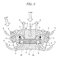
- Fig. 6 is a sectional view showing a rotor part in a second embodiment of this invention.
- the arrangement of the short circuit coil 8 is different from that of the first embodiment.
- the short circuit coil 8 is provided in a permanent magnet (NdFeB magnet 4) other than the "permanent magnet to be irreversibly changed", on the stator side of the "other magnet” (NdFeB magnet 4) such that an axis extending in the magnetization direction in the center part of the "other magnets" (NdFeB magnet 4) is the center axis of the short circuit coil 8.
- the short circuit coil 8 is embedded in the rotor core 2 such that the short circuit coil 8 faces the "other magnet” (NdFeB magnet 4) with leaving a space between them.
- a magnetic field generated by a magnetization current induces an induced current in the short circuit coil 8. Then the magnetic field C generated by the induced current and the magnetic field A magnetize the ferrite magnet 3 in the magnetization direction. At the same time, since the magnetic field C of the short circuit coil 8 also act such as to counteracts the magnetic field A due to a magnetization current generated in the armature core 11, a magnetic saturation of the armature core 11 can be alleviated.
- the short circuit coil denoted by a symbol “8" in Fig. 6 is located on the stator side of the NdFeB magnet 4, but the location of the short circuit coil is not limited to that place, as denoted by a dashed line and symbol “(8) ", the short circuit coil also can be located on the center side of the rotor core 2 compared with the NdFeB magnet 4.
- the short circuit coil may be wound about the rotor core 2, in the surrounding part of the NdFeB magnet 4, on the center or outer side of the rotor core 2 compared with the NdFeB magnet 4, in this case, the same effects can be obtained.
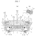
- Fig. 7(a) is a sectional view showing a rotor part in a third embodiment of this invention
- Fig. 7(b) is a partial enlarged sectional view showing in an enlarged manner a part of the rotor core shown in Fig. 7(a)
- the short circuit coil is provided in the rotor core 2, in a magnetic path part that allows a magnetic flux to leak, which is other than the "permanent magnet to be irreversibly changed" 3.
- short circuit coils 8a and 8b are provided in "magnetic path parts that allows a magnetic flux to leak" of the rotor core 2 in the radial direction of the location of the "permanent magnet to be irreversibly changes" 3, and other than the permanent magnet 3.
- narrow parts 2a and 2b of the core are formed between the cavities 5 provided at the opposite ends of the "permanent magnet to be irreversibly changed" 3, and the surfaces of the outer and center sides of the rotor core 2.
- these narrow parts 2a and 2b correspond to the "magnetic path parts that allows a magnetic flux to leak" other than the "permanent magnet to be irreversibly changed" 3.
- short circuit coils 8a and 8b that have a small diameter and act such as to counteract the leakage flux L passing through the parts, are provided, respectively.
- the short circuit coil 8a is omitted in Fig. 7 (a) , and is only shown in the partial enlarged sectional view of Fig. 7(b) .
- the small diameter short circuit coil 8a of the path part 2a is provided such that an axis extending in the direction of the leakage flux L is the center axis of the short circuit coil 8a.
- the small diameter short circuit coil 8b of the path part 2b is provided as with the short circuit coil 8a.
- the magnetic path parts 2a and 2b that allow the leakage flux L to be generated form a parallel circuit as a magnetic circuit in relation to the "permanent magnet to be irreversibly changed" 3. Consequently, the magnetic field D, which is generated the small diameter short circuit coils 8a and 8b and acts such as to counteract the leakage flux L, also acts on the "permanent magnet to be irreversibly changed" 3, which is magnetically connected the leakage flux part. Since the directions of the magnetic field D is the same as that of the magnetic field A, an effect of promotion of magnetizing the "permanent magnet to be irreversibly changed" 3, can be obtained.
- Fig. 8 is a sectional view showing a rotor part in a fourth embodiment of this invention.
- a conductive plate 9 instead of the short circuit coil 8, is provided on a surface that faces a surface of the NdFeB magnet 4, the surface of which is shown as one main surface on the bottom side of the NdFeB magnet 4 in the drawing view (the center side of the rotor). That is, the conductive plate 9 is provided on a surface that faces the NdFeB magnet 4 in the magnetization direction thereof.
- a copper plate or an aluminum plate is used as the conductive plate 9.
- the conductive plate 9 not limited to the location on the bottom side of the NdFeB magnet 4 in the drawing view (the center side of the rotor), also may be located on the top side of the NdFeB magnet 4 in the drawing view (the outer side of the rotor).
- a merit can be obtained in which current harmonics or slot harmonics generate an induced current in the conductive plate to reduce the harmonics.
- the magnetic field generated by a magnetization current when the magnetic field generated by a magnetization current is applied to the conductive plate 9, an induced current (eddy current) is generated in a surface part of the conductive plate 9, as a result, the magnetic field C is generated, as with the short circuit coil 8.
- the magnetic field C allows a magnetic force to be applied to the ferrite magnet 3 to allow the magnetization to be performed effectively.
- a magnetic saturation of the armature core 11 can be alleviated.
Landscapes
- Engineering & Computer Science (AREA)
- Power Engineering (AREA)
- Permanent Field Magnets Of Synchronous Machinery (AREA)
- Permanent Magnet Type Synchronous Machine (AREA)
Applications Claiming Priority (2)
| Application Number | Priority Date | Filing Date | Title |
|---|---|---|---|
| JP2008162203A JP5305753B2 (ja) | 2008-06-20 | 2008-06-20 | 永久磁石式回転電機 |
| PCT/JP2009/002812 WO2009154007A1 (ja) | 2008-06-20 | 2009-06-19 | 永久磁石式回転電機 |
Publications (3)
| Publication Number | Publication Date |
|---|---|
| EP2299558A1 true EP2299558A1 (de) | 2011-03-23 |
| EP2299558A4 EP2299558A4 (de) | 2016-06-29 |
| EP2299558B1 EP2299558B1 (de) | 2019-07-24 |
Family
ID=41433925
Family Applications (1)
| Application Number | Title | Priority Date | Filing Date |
|---|---|---|---|
| EP09766455.1A Active EP2299558B1 (de) | 2008-06-20 | 2009-06-19 | Elektrische drehmaschine des permanentmagnettyps |
Country Status (5)
| Country | Link |
|---|---|
| US (1) | US8674575B2 (de) |
| EP (1) | EP2299558B1 (de) |
| JP (1) | JP5305753B2 (de) |
| CN (2) | CN103779994B (de) |
| WO (1) | WO2009154007A1 (de) |
Cited By (7)
| Publication number | Priority date | Publication date | Assignee | Title |
|---|---|---|---|---|
| WO2014118102A3 (de) * | 2013-01-31 | 2014-12-18 | Robert Bosch Gmbh | Bestimmung einer flussverkettung |
| US8928198B2 (en) | 2011-02-28 | 2015-01-06 | Uqm Technologies Inc. | Brushless PM machine construction enabling low coercivity magnets |
| DE102019130986A1 (de) * | 2019-11-15 | 2021-05-20 | Hiwin Mikrosystem Corp. | Rotorstruktur eines Permanentmagnetmotors |
| EP3915182A4 (de) * | 2019-03-20 | 2022-03-02 | Magna International Inc | Permanentmagnetunterstützter synchroner reluktanzmotor |
| EP3836354A4 (de) * | 2018-08-09 | 2022-05-11 | Nidec Corporation | Rotor, synchroner reluktanzmotor und verfahren zur herstellung des rotors |
| EP4418497A1 (de) * | 2023-01-31 | 2024-08-21 | Mazda Motor Corporation | Permanentmagnet-rotor |
| EP4412042A3 (de) * | 2023-01-31 | 2024-11-27 | Mazda Motor Corporation | Dauermagnetrotor für eine rotierende elektrische maschine |
Families Citing this family (32)
| Publication number | Priority date | Publication date | Assignee | Title |
|---|---|---|---|---|
| WO2011132250A1 (ja) * | 2010-04-19 | 2011-10-27 | トヨタ自動車株式会社 | 磁石埋め込み型同期モータ用ロータ |
| JP5802487B2 (ja) * | 2011-08-30 | 2015-10-28 | 株式会社東芝 | 永久磁石式回転電機 |
| CN102647066A (zh) * | 2012-04-21 | 2012-08-22 | 山东理工大学 | 电磁与双径向永磁混合励磁发电机 |
| CN102647065A (zh) * | 2012-04-21 | 2012-08-22 | 山东理工大学 | 无刷电磁与混合磁路复合励磁发电机 |
| CN102638147A (zh) * | 2012-04-26 | 2012-08-15 | 张学义 | 永磁与电磁串联磁场混合励磁发电机 |
| CN102710083B (zh) * | 2012-06-06 | 2014-02-12 | 程开业 | 混合励磁无刷直流风力发电机 |
| DE102012209905A1 (de) * | 2012-06-13 | 2013-12-19 | Krones Ag | Verschließer für Behälter |
| JP5975759B2 (ja) * | 2012-06-29 | 2016-08-23 | 株式会社日立製作所 | 回転電機 |
| MX347464B (es) | 2012-09-29 | 2017-04-26 | Emerson Electric Co | Rotores con configuraciones de iman segmentado y maquinas dinamoeléctricas y compresores relacionados. |
| DE102012218993A1 (de) * | 2012-10-18 | 2014-04-24 | Robert Bosch Gmbh | Läuferanordnung für eine permanentmagneterregte elektrische Maschine |
| WO2014144540A1 (en) * | 2013-03-15 | 2014-09-18 | Flux Energy Systems, Llc | Electric motor |
| US9698660B2 (en) | 2013-10-25 | 2017-07-04 | General Electric Company | System and method for heating ferrite magnet motors for low temperatures |
| CN103683731A (zh) * | 2013-12-05 | 2014-03-26 | 张学义 | 电动汽车增程器用混合励磁发电装置转子生产方法 |
| CN103647422B (zh) * | 2013-12-09 | 2016-08-17 | 江苏大学 | 一种采用混合永磁材料的磁路串联型电机 |
| DE102014016452B4 (de) * | 2014-11-06 | 2019-03-28 | Audi Ag | Verfahren zum Ermitteln einer Statorwicklungstemperatur einer elektrischen Maschine |
| CN105811684A (zh) * | 2016-05-11 | 2016-07-27 | 山东理工大学 | 电动汽车径向与内置切向永磁钢驱动电机转子生产方法 |
| CN105790471A (zh) * | 2016-05-11 | 2016-07-20 | 山东理工大学 | 永磁发电机与真空泵一体化装置 |
| CN105811704A (zh) * | 2016-05-11 | 2016-07-27 | 山东理工大学 | 复合永磁隐形磁极与无刷电磁混合励磁驱动电机 |
| WO2018146604A1 (en) * | 2017-02-13 | 2018-08-16 | Tvs Motor Company Limited | Auxiliary coil for an electric machine |
| WO2019049392A1 (ja) * | 2017-09-11 | 2019-03-14 | 株式会社 東芝 | 回転電機 |
| US11509202B2 (en) * | 2017-12-28 | 2022-11-22 | Abb Schweiz Ag | Variable flux permanent magnet motor |
| US11056939B2 (en) * | 2018-07-05 | 2021-07-06 | Aisin Aw Co., Ltd. | Rotor with stress relaxation magnetic flux suppression holes with flux paths width less than length of the hole |
| KR102177140B1 (ko) | 2019-01-18 | 2020-11-10 | 효성중공업 주식회사 | 액츄에이터 |
| CN110212664A (zh) * | 2019-03-27 | 2019-09-06 | 曾庆维 | 可调式节能惯量动能输出系统及其控制方法 |
| JP7284503B2 (ja) * | 2019-08-05 | 2023-05-31 | 国立大学法人 岡山大学 | 可変磁力モータ |
| CN110676961A (zh) * | 2019-09-25 | 2020-01-10 | 合肥巨一动力系统有限公司 | 一种抑制隔磁桥漏磁的永磁电机转子 |
| US11462960B2 (en) * | 2019-12-02 | 2022-10-04 | Hiwin Mikrosystem Corp. | Rotor with first and second permanent magnets having support members and slots |
| CN111816437A (zh) * | 2020-07-28 | 2020-10-23 | 安徽中富磁电有限公司 | 一种高频焊接磁棒的制造工艺 |
| CN112234778A (zh) * | 2020-09-29 | 2021-01-15 | 中车永济电机有限公司 | 永磁电机运输时的轴承防护方法 |
| CN113014009B (zh) * | 2021-03-08 | 2022-11-01 | 哈尔滨工业大学 | 永磁体串并联式变磁路可调磁通电机 |
| CN115642768B (zh) * | 2022-11-04 | 2025-08-05 | 上海交通大学 | 环形调磁绕组记忆电机及调磁方法 |
| CN117559689B (zh) * | 2024-01-12 | 2024-04-05 | 苏州英磁新能源科技有限公司 | 一种内置式电机磁场调节系统 |
Family Cites Families (13)
| Publication number | Priority date | Publication date | Assignee | Title |
|---|---|---|---|---|
| JPS57145556A (en) * | 1981-03-02 | 1982-09-08 | Hitachi Ltd | Electric rotary machine |
| JP3133224B2 (ja) * | 1994-12-27 | 2001-02-05 | 財団法人鉄道総合技術研究所 | 車両用永久磁石励磁同期電動機 |
| CN1210860C (zh) * | 1999-07-16 | 2005-07-13 | 松下电器产业株式会社 | 永久磁铁同步电动机 |
| EP1487084B1 (de) * | 2002-03-20 | 2014-08-06 | Daikin Industries, Ltd. | Motor des permanentmagnettyps und kompressor damit |
| JP2006060952A (ja) * | 2004-08-23 | 2006-03-02 | Matsushita Electric Ind Co Ltd | 永久磁石埋込み型電動機 |
| JP5398103B2 (ja) | 2005-03-01 | 2014-01-29 | 株式会社東芝 | 永久磁石式回転電機 |
| JP2006288183A (ja) * | 2005-03-09 | 2006-10-19 | Nissan Motor Co Ltd | 電動機 |
| JP4965924B2 (ja) * | 2006-07-24 | 2012-07-04 | 株式会社東芝 | 可変磁束ドライブシステム |
| JP5208400B2 (ja) * | 2006-11-10 | 2013-06-12 | 株式会社東芝 | 可変磁束モータドライブシステム |
| CA2659088C (en) * | 2006-07-24 | 2013-07-09 | Kabushiki Kaisha Toshiba | Variable-flux motor drive system |
| JP5085071B2 (ja) | 2006-08-11 | 2012-11-28 | 株式会社東芝 | 永久磁石式回転電機の回転子 |
| JP2008046514A (ja) | 2006-08-18 | 2008-02-28 | Mitsubishi Chemicals Corp | 静電荷像現像用トナーの製造方法 |
| US8044548B2 (en) * | 2006-08-23 | 2011-10-25 | Kabushiki Kaisha Toshiba | Permanent-magnet-type rotating electrical machine |
-
2008
- 2008-06-20 JP JP2008162203A patent/JP5305753B2/ja active Active
-
2009
- 2009-06-19 CN CN201410061290.0A patent/CN103779994B/zh active Active
- 2009-06-19 CN CN200980123036.6A patent/CN102067412B/zh active Active
- 2009-06-19 US US13/000,227 patent/US8674575B2/en active Active
- 2009-06-19 EP EP09766455.1A patent/EP2299558B1/de active Active
- 2009-06-19 WO PCT/JP2009/002812 patent/WO2009154007A1/ja not_active Ceased
Non-Patent Citations (1)
| Title |
|---|
| See references of WO2009154007A1 * |
Cited By (7)
| Publication number | Priority date | Publication date | Assignee | Title |
|---|---|---|---|---|
| US8928198B2 (en) | 2011-02-28 | 2015-01-06 | Uqm Technologies Inc. | Brushless PM machine construction enabling low coercivity magnets |
| WO2014118102A3 (de) * | 2013-01-31 | 2014-12-18 | Robert Bosch Gmbh | Bestimmung einer flussverkettung |
| EP3836354A4 (de) * | 2018-08-09 | 2022-05-11 | Nidec Corporation | Rotor, synchroner reluktanzmotor und verfahren zur herstellung des rotors |
| EP3915182A4 (de) * | 2019-03-20 | 2022-03-02 | Magna International Inc | Permanentmagnetunterstützter synchroner reluktanzmotor |
| DE102019130986A1 (de) * | 2019-11-15 | 2021-05-20 | Hiwin Mikrosystem Corp. | Rotorstruktur eines Permanentmagnetmotors |
| EP4418497A1 (de) * | 2023-01-31 | 2024-08-21 | Mazda Motor Corporation | Permanentmagnet-rotor |
| EP4412042A3 (de) * | 2023-01-31 | 2024-11-27 | Mazda Motor Corporation | Dauermagnetrotor für eine rotierende elektrische maschine |
Also Published As
| Publication number | Publication date |
|---|---|
| CN102067412A (zh) | 2011-05-18 |
| EP2299558B1 (de) | 2019-07-24 |
| US8674575B2 (en) | 2014-03-18 |
| JP5305753B2 (ja) | 2013-10-02 |
| JP2010004672A (ja) | 2010-01-07 |
| CN103779994A (zh) | 2014-05-07 |
| CN102067412B (zh) | 2014-07-16 |
| US20110175478A1 (en) | 2011-07-21 |
| WO2009154007A1 (ja) | 2009-12-23 |
| EP2299558A4 (de) | 2016-06-29 |
| CN103779994B (zh) | 2016-09-07 |
Similar Documents
| Publication | Publication Date | Title |
|---|---|---|
| EP2299558B1 (de) | Elektrische drehmaschine des permanentmagnettyps | |
| EP2360814B1 (de) | Elektrische drehmaschine mit permanentmagnet | |
| JP5361261B2 (ja) | 永久磁石式回転電機 | |
| Hua et al. | A novel variable flux memory machine with series hybrid magnets | |
| JP5085071B2 (ja) | 永久磁石式回転電機の回転子 | |
| Sakai et al. | Principle of the variable-magnetic-force memory motor | |
| US8242653B2 (en) | Magnetic flux controllable rotating electric machine system | |
| JP5159171B2 (ja) | 永久磁石式回転電機 | |
| JP5787673B2 (ja) | 永久磁石型回転電機 | |
| JP5355055B2 (ja) | 永久磁石式回転電機 | |
| WO2011046070A1 (ja) | 磁束量可変回転電機システム | |
| JP2010004671A (ja) | 永久磁石回転式電機 | |
| JPWO2019050050A1 (ja) | 回転子および回転電機 | |
| JP2012175738A (ja) | 永久磁石式回転電機 | |
| JP5178488B2 (ja) | 永久磁石式回転電機 | |
| JP2012029563A (ja) | 永久磁石式回転電機 | |
| JP4735772B1 (ja) | 磁石励磁回転電機システム | |
| Yokomichi et al. | A proposal of hybrid excitation variable flux memory motor having field winding with magnetization function in the rotor | |
| JP2011172323A (ja) | 永久磁石式回転電機 | |
| JP5390314B2 (ja) | 永久磁石式回転電機 | |
| Namba et al. | Variable-field machine with three-dimensional magnetic circuit for traction motor | |
| Misu et al. | Variable Magnetomotive Force Memory Motor for Electric Vehicles |
Legal Events
| Date | Code | Title | Description |
|---|---|---|---|
| PUAI | Public reference made under article 153(3) epc to a published international application that has entered the european phase |
Free format text: ORIGINAL CODE: 0009012 |
|
| 17P | Request for examination filed |
Effective date: 20101220 |
|
| AK | Designated contracting states |
Kind code of ref document: A1 Designated state(s): AT BE BG CH CY CZ DE DK EE ES FI FR GB GR HR HU IE IS IT LI LT LU LV MC MK MT NL NO PL PT RO SE SI SK TR |
|
| AX | Request for extension of the european patent |
Extension state: AL BA RS |
|
| RIN1 | Information on inventor provided before grant (corrected) |
Inventor name: OTSUBO, YOSUKE Inventor name: SAKAI, KAZUTO Inventor name: TOKUMASU, TADASHI Inventor name: TAKAHASHI, NORIO Inventor name: MATSUOKA, YUSUKE Inventor name: HASHIBA, YUTAKA |
|
| DAX | Request for extension of the european patent (deleted) | ||
| RA4 | Supplementary search report drawn up and despatched (corrected) |
Effective date: 20160601 |
|
| RIC1 | Information provided on ipc code assigned before grant |
Ipc: H02K 1/27 20060101AFI20160526BHEP |
|
| STAA | Information on the status of an ep patent application or granted ep patent |
Free format text: STATUS: EXAMINATION IS IN PROGRESS |
|
| 17Q | First examination report despatched |
Effective date: 20170126 |
|
| 17Q | First examination report despatched |
Effective date: 20170202 |
|
| GRAP | Despatch of communication of intention to grant a patent |
Free format text: ORIGINAL CODE: EPIDOSNIGR1 |
|
| STAA | Information on the status of an ep patent application or granted ep patent |
Free format text: STATUS: GRANT OF PATENT IS INTENDED |
|
| INTG | Intention to grant announced |
Effective date: 20190312 |
|
| GRAS | Grant fee paid |
Free format text: ORIGINAL CODE: EPIDOSNIGR3 |
|
| GRAA | (expected) grant |
Free format text: ORIGINAL CODE: 0009210 |
|
| STAA | Information on the status of an ep patent application or granted ep patent |
Free format text: STATUS: THE PATENT HAS BEEN GRANTED |
|
| AK | Designated contracting states |
Kind code of ref document: B1 Designated state(s): AT BE BG CH CY CZ DE DK EE ES FI FR GB GR HR HU IE IS IT LI LT LU LV MC MK MT NL NO PL PT RO SE SI SK TR |
|
| REG | Reference to a national code |
Ref country code: GB Ref legal event code: FG4D |
|
| REG | Reference to a national code |
Ref country code: CH Ref legal event code: EP |
|
| REG | Reference to a national code |
Ref country code: DE Ref legal event code: R096 Ref document number: 602009059230 Country of ref document: DE |
|
| REG | Reference to a national code |
Ref country code: AT Ref legal event code: REF Ref document number: 1159379 Country of ref document: AT Kind code of ref document: T Effective date: 20190815 |
|
| REG | Reference to a national code |
Ref country code: IE Ref legal event code: FG4D |
|
| REG | Reference to a national code |
Ref country code: NL Ref legal event code: MP Effective date: 20190724 |
|
| REG | Reference to a national code |
Ref country code: LT Ref legal event code: MG4D |
|
| REG | Reference to a national code |
Ref country code: AT Ref legal event code: MK05 Ref document number: 1159379 Country of ref document: AT Kind code of ref document: T Effective date: 20190724 |
|
| PG25 | Lapsed in a contracting state [announced via postgrant information from national office to epo] |
Ref country code: PT Free format text: LAPSE BECAUSE OF FAILURE TO SUBMIT A TRANSLATION OF THE DESCRIPTION OR TO PAY THE FEE WITHIN THE PRESCRIBED TIME-LIMIT Effective date: 20191125 Ref country code: LT Free format text: LAPSE BECAUSE OF FAILURE TO SUBMIT A TRANSLATION OF THE DESCRIPTION OR TO PAY THE FEE WITHIN THE PRESCRIBED TIME-LIMIT Effective date: 20190724 Ref country code: BG Free format text: LAPSE BECAUSE OF FAILURE TO SUBMIT A TRANSLATION OF THE DESCRIPTION OR TO PAY THE FEE WITHIN THE PRESCRIBED TIME-LIMIT Effective date: 20191024 Ref country code: SE Free format text: LAPSE BECAUSE OF FAILURE TO SUBMIT A TRANSLATION OF THE DESCRIPTION OR TO PAY THE FEE WITHIN THE PRESCRIBED TIME-LIMIT Effective date: 20190724 Ref country code: NL Free format text: LAPSE BECAUSE OF FAILURE TO SUBMIT A TRANSLATION OF THE DESCRIPTION OR TO PAY THE FEE WITHIN THE PRESCRIBED TIME-LIMIT Effective date: 20190724 Ref country code: AT Free format text: LAPSE BECAUSE OF FAILURE TO SUBMIT A TRANSLATION OF THE DESCRIPTION OR TO PAY THE FEE WITHIN THE PRESCRIBED TIME-LIMIT Effective date: 20190724 Ref country code: NO Free format text: LAPSE BECAUSE OF FAILURE TO SUBMIT A TRANSLATION OF THE DESCRIPTION OR TO PAY THE FEE WITHIN THE PRESCRIBED TIME-LIMIT Effective date: 20191024 Ref country code: HR Free format text: LAPSE BECAUSE OF FAILURE TO SUBMIT A TRANSLATION OF THE DESCRIPTION OR TO PAY THE FEE WITHIN THE PRESCRIBED TIME-LIMIT Effective date: 20190724 Ref country code: FI Free format text: LAPSE BECAUSE OF FAILURE TO SUBMIT A TRANSLATION OF THE DESCRIPTION OR TO PAY THE FEE WITHIN THE PRESCRIBED TIME-LIMIT Effective date: 20190724 |
|
| PG25 | Lapsed in a contracting state [announced via postgrant information from national office to epo] |
Ref country code: GR Free format text: LAPSE BECAUSE OF FAILURE TO SUBMIT A TRANSLATION OF THE DESCRIPTION OR TO PAY THE FEE WITHIN THE PRESCRIBED TIME-LIMIT Effective date: 20191025 Ref country code: ES Free format text: LAPSE BECAUSE OF FAILURE TO SUBMIT A TRANSLATION OF THE DESCRIPTION OR TO PAY THE FEE WITHIN THE PRESCRIBED TIME-LIMIT Effective date: 20190724 Ref country code: IS Free format text: LAPSE BECAUSE OF FAILURE TO SUBMIT A TRANSLATION OF THE DESCRIPTION OR TO PAY THE FEE WITHIN THE PRESCRIBED TIME-LIMIT Effective date: 20191124 Ref country code: LV Free format text: LAPSE BECAUSE OF FAILURE TO SUBMIT A TRANSLATION OF THE DESCRIPTION OR TO PAY THE FEE WITHIN THE PRESCRIBED TIME-LIMIT Effective date: 20190724 |
|
| PG25 | Lapsed in a contracting state [announced via postgrant information from national office to epo] |
Ref country code: TR Free format text: LAPSE BECAUSE OF FAILURE TO SUBMIT A TRANSLATION OF THE DESCRIPTION OR TO PAY THE FEE WITHIN THE PRESCRIBED TIME-LIMIT Effective date: 20190724 |
|
| PG25 | Lapsed in a contracting state [announced via postgrant information from national office to epo] |
Ref country code: DK Free format text: LAPSE BECAUSE OF FAILURE TO SUBMIT A TRANSLATION OF THE DESCRIPTION OR TO PAY THE FEE WITHIN THE PRESCRIBED TIME-LIMIT Effective date: 20190724 Ref country code: RO Free format text: LAPSE BECAUSE OF FAILURE TO SUBMIT A TRANSLATION OF THE DESCRIPTION OR TO PAY THE FEE WITHIN THE PRESCRIBED TIME-LIMIT Effective date: 20190724 Ref country code: EE Free format text: LAPSE BECAUSE OF FAILURE TO SUBMIT A TRANSLATION OF THE DESCRIPTION OR TO PAY THE FEE WITHIN THE PRESCRIBED TIME-LIMIT Effective date: 20190724 Ref country code: PL Free format text: LAPSE BECAUSE OF FAILURE TO SUBMIT A TRANSLATION OF THE DESCRIPTION OR TO PAY THE FEE WITHIN THE PRESCRIBED TIME-LIMIT Effective date: 20190724 |
|
| PG25 | Lapsed in a contracting state [announced via postgrant information from national office to epo] |
Ref country code: IS Free format text: LAPSE BECAUSE OF FAILURE TO SUBMIT A TRANSLATION OF THE DESCRIPTION OR TO PAY THE FEE WITHIN THE PRESCRIBED TIME-LIMIT Effective date: 20200224 Ref country code: SK Free format text: LAPSE BECAUSE OF FAILURE TO SUBMIT A TRANSLATION OF THE DESCRIPTION OR TO PAY THE FEE WITHIN THE PRESCRIBED TIME-LIMIT Effective date: 20190724 Ref country code: CZ Free format text: LAPSE BECAUSE OF FAILURE TO SUBMIT A TRANSLATION OF THE DESCRIPTION OR TO PAY THE FEE WITHIN THE PRESCRIBED TIME-LIMIT Effective date: 20190724 |
|
| REG | Reference to a national code |
Ref country code: DE Ref legal event code: R097 Ref document number: 602009059230 Country of ref document: DE |
|
| PLBE | No opposition filed within time limit |
Free format text: ORIGINAL CODE: 0009261 |
|
| STAA | Information on the status of an ep patent application or granted ep patent |
Free format text: STATUS: NO OPPOSITION FILED WITHIN TIME LIMIT |
|
| PG2D | Information on lapse in contracting state deleted |
Ref country code: IS |
|
| 26N | No opposition filed |
Effective date: 20200603 |
|
| PG25 | Lapsed in a contracting state [announced via postgrant information from national office to epo] |
Ref country code: SI Free format text: LAPSE BECAUSE OF FAILURE TO SUBMIT A TRANSLATION OF THE DESCRIPTION OR TO PAY THE FEE WITHIN THE PRESCRIBED TIME-LIMIT Effective date: 20190724 |
|
| PG25 | Lapsed in a contracting state [announced via postgrant information from national office to epo] |
Ref country code: MC Free format text: LAPSE BECAUSE OF FAILURE TO SUBMIT A TRANSLATION OF THE DESCRIPTION OR TO PAY THE FEE WITHIN THE PRESCRIBED TIME-LIMIT Effective date: 20190724 |
|
| REG | Reference to a national code |
Ref country code: CH Ref legal event code: PL |
|
| GBPC | Gb: european patent ceased through non-payment of renewal fee |
Effective date: 20200619 |
|
| PG25 | Lapsed in a contracting state [announced via postgrant information from national office to epo] |
Ref country code: LU Free format text: LAPSE BECAUSE OF NON-PAYMENT OF DUE FEES Effective date: 20200619 |
|
| REG | Reference to a national code |
Ref country code: BE Ref legal event code: MM Effective date: 20200630 |
|
| PG25 | Lapsed in a contracting state [announced via postgrant information from national office to epo] |
Ref country code: GB Free format text: LAPSE BECAUSE OF NON-PAYMENT OF DUE FEES Effective date: 20200619 Ref country code: CH Free format text: LAPSE BECAUSE OF NON-PAYMENT OF DUE FEES Effective date: 20200630 Ref country code: LI Free format text: LAPSE BECAUSE OF NON-PAYMENT OF DUE FEES Effective date: 20200630 Ref country code: IE Free format text: LAPSE BECAUSE OF NON-PAYMENT OF DUE FEES Effective date: 20200619 |
|
| PG25 | Lapsed in a contracting state [announced via postgrant information from national office to epo] |
Ref country code: BE Free format text: LAPSE BECAUSE OF NON-PAYMENT OF DUE FEES Effective date: 20200630 |
|
| PGFP | Annual fee paid to national office [announced via postgrant information from national office to epo] |
Ref country code: FR Payment date: 20210513 Year of fee payment: 13 Ref country code: IT Payment date: 20210511 Year of fee payment: 13 |
|
| PG25 | Lapsed in a contracting state [announced via postgrant information from national office to epo] |
Ref country code: MT Free format text: LAPSE BECAUSE OF FAILURE TO SUBMIT A TRANSLATION OF THE DESCRIPTION OR TO PAY THE FEE WITHIN THE PRESCRIBED TIME-LIMIT Effective date: 20190724 Ref country code: CY Free format text: LAPSE BECAUSE OF FAILURE TO SUBMIT A TRANSLATION OF THE DESCRIPTION OR TO PAY THE FEE WITHIN THE PRESCRIBED TIME-LIMIT Effective date: 20190724 |
|
| PG25 | Lapsed in a contracting state [announced via postgrant information from national office to epo] |
Ref country code: MK Free format text: LAPSE BECAUSE OF FAILURE TO SUBMIT A TRANSLATION OF THE DESCRIPTION OR TO PAY THE FEE WITHIN THE PRESCRIBED TIME-LIMIT Effective date: 20190724 |
|
| PG25 | Lapsed in a contracting state [announced via postgrant information from national office to epo] |
Ref country code: FR Free format text: LAPSE BECAUSE OF NON-PAYMENT OF DUE FEES Effective date: 20220630 |
|
| PG25 | Lapsed in a contracting state [announced via postgrant information from national office to epo] |
Ref country code: IT Free format text: LAPSE BECAUSE OF NON-PAYMENT OF DUE FEES Effective date: 20220619 |
|
| PGFP | Annual fee paid to national office [announced via postgrant information from national office to epo] |
Ref country code: DE Payment date: 20250402 Year of fee payment: 17 |