EP2299716B1 - Procédé et dispositif pour le codage d'un signal numérique multidimensionnel - Google Patents
Procédé et dispositif pour le codage d'un signal numérique multidimensionnel Download PDFInfo
- Publication number
- EP2299716B1 EP2299716B1 EP09305826.1A EP09305826A EP2299716B1 EP 2299716 B1 EP2299716 B1 EP 2299716B1 EP 09305826 A EP09305826 A EP 09305826A EP 2299716 B1 EP2299716 B1 EP 2299716B1
- Authority
- EP
- European Patent Office
- Prior art keywords
- samples
- filtered
- sub
- 1dec
- modified
- Prior art date
- Legal status (The legal status is an assumption and is not a legal conclusion. Google has not performed a legal analysis and makes no representation as to the accuracy of the status listed.)
- Not-in-force
Links
Images




Classifications
-
- H—ELECTRICITY
- H04—ELECTRIC COMMUNICATION TECHNIQUE
- H04N—PICTORIAL COMMUNICATION, e.g. TELEVISION
- H04N19/00—Methods or arrangements for coding, decoding, compressing or decompressing digital video signals
- H04N19/60—Methods or arrangements for coding, decoding, compressing or decompressing digital video signals using transform coding
- H04N19/63—Methods or arrangements for coding, decoding, compressing or decompressing digital video signals using transform coding using sub-band based transform, e.g. wavelets
- H04N19/635—Methods or arrangements for coding, decoding, compressing or decompressing digital video signals using transform coding using sub-band based transform, e.g. wavelets characterised by filter definition or implementation details
-
- H—ELECTRICITY
- H04—ELECTRIC COMMUNICATION TECHNIQUE
- H04N—PICTORIAL COMMUNICATION, e.g. TELEVISION
- H04N19/00—Methods or arrangements for coding, decoding, compressing or decompressing digital video signals
- H04N19/10—Methods or arrangements for coding, decoding, compressing or decompressing digital video signals using adaptive coding
- H04N19/102—Methods or arrangements for coding, decoding, compressing or decompressing digital video signals using adaptive coding characterised by the element, parameter or selection affected or controlled by the adaptive coding
- H04N19/103—Selection of coding mode or of prediction mode
- H04N19/11—Selection of coding mode or of prediction mode among a plurality of spatial predictive coding modes
-
- H—ELECTRICITY
- H04—ELECTRIC COMMUNICATION TECHNIQUE
- H04N—PICTORIAL COMMUNICATION, e.g. TELEVISION
- H04N19/00—Methods or arrangements for coding, decoding, compressing or decompressing digital video signals
- H04N19/10—Methods or arrangements for coding, decoding, compressing or decompressing digital video signals using adaptive coding
- H04N19/102—Methods or arrangements for coding, decoding, compressing or decompressing digital video signals using adaptive coding characterised by the element, parameter or selection affected or controlled by the adaptive coding
- H04N19/117—Filters, e.g. for pre-processing or post-processing
-
- H—ELECTRICITY
- H04—ELECTRIC COMMUNICATION TECHNIQUE
- H04N—PICTORIAL COMMUNICATION, e.g. TELEVISION
- H04N19/00—Methods or arrangements for coding, decoding, compressing or decompressing digital video signals
- H04N19/10—Methods or arrangements for coding, decoding, compressing or decompressing digital video signals using adaptive coding
- H04N19/102—Methods or arrangements for coding, decoding, compressing or decompressing digital video signals using adaptive coding characterised by the element, parameter or selection affected or controlled by the adaptive coding
- H04N19/12—Selection from among a plurality of transforms or standards, e.g. selection between discrete cosine transform [DCT] and sub-band transform or selection between H.263 and H.264
- H04N19/122—Selection of transform size, e.g. 8x8 or 2x4x8 DCT; Selection of sub-band transforms of varying structure or type
-
- H—ELECTRICITY
- H04—ELECTRIC COMMUNICATION TECHNIQUE
- H04N—PICTORIAL COMMUNICATION, e.g. TELEVISION
- H04N19/00—Methods or arrangements for coding, decoding, compressing or decompressing digital video signals
- H04N19/10—Methods or arrangements for coding, decoding, compressing or decompressing digital video signals using adaptive coding
- H04N19/134—Methods or arrangements for coding, decoding, compressing or decompressing digital video signals using adaptive coding characterised by the element, parameter or criterion affecting or controlling the adaptive coding
- H04N19/136—Incoming video signal characteristics or properties
- H04N19/14—Coding unit complexity, e.g. amount of activity or edge presence estimation
-
- H—ELECTRICITY
- H04—ELECTRIC COMMUNICATION TECHNIQUE
- H04N—PICTORIAL COMMUNICATION, e.g. TELEVISION
- H04N19/00—Methods or arrangements for coding, decoding, compressing or decompressing digital video signals
- H04N19/10—Methods or arrangements for coding, decoding, compressing or decompressing digital video signals using adaptive coding
- H04N19/134—Methods or arrangements for coding, decoding, compressing or decompressing digital video signals using adaptive coding characterised by the element, parameter or criterion affecting or controlling the adaptive coding
- H04N19/146—Data rate or code amount at the encoder output
- H04N19/147—Data rate or code amount at the encoder output according to rate distortion criteria
-
- H—ELECTRICITY
- H04—ELECTRIC COMMUNICATION TECHNIQUE
- H04N—PICTORIAL COMMUNICATION, e.g. TELEVISION
- H04N19/00—Methods or arrangements for coding, decoding, compressing or decompressing digital video signals
- H04N19/10—Methods or arrangements for coding, decoding, compressing or decompressing digital video signals using adaptive coding
- H04N19/169—Methods or arrangements for coding, decoding, compressing or decompressing digital video signals using adaptive coding characterised by the coding unit, i.e. the structural portion or semantic portion of the video signal being the object or the subject of the adaptive coding
- H04N19/17—Methods or arrangements for coding, decoding, compressing or decompressing digital video signals using adaptive coding characterised by the coding unit, i.e. the structural portion or semantic portion of the video signal being the object or the subject of the adaptive coding the unit being an image region, e.g. an object
- H04N19/172—Methods or arrangements for coding, decoding, compressing or decompressing digital video signals using adaptive coding characterised by the coding unit, i.e. the structural portion or semantic portion of the video signal being the object or the subject of the adaptive coding the unit being an image region, e.g. an object the region being a picture, frame or field
-
- H—ELECTRICITY
- H04—ELECTRIC COMMUNICATION TECHNIQUE
- H04N—PICTORIAL COMMUNICATION, e.g. TELEVISION
- H04N19/00—Methods or arrangements for coding, decoding, compressing or decompressing digital video signals
- H04N19/46—Embedding additional information in the video signal during the compression process
-
- H—ELECTRICITY
- H04—ELECTRIC COMMUNICATION TECHNIQUE
- H04N—PICTORIAL COMMUNICATION, e.g. TELEVISION
- H04N19/00—Methods or arrangements for coding, decoding, compressing or decompressing digital video signals
- H04N19/46—Embedding additional information in the video signal during the compression process
- H04N19/463—Embedding additional information in the video signal during the compression process by compressing encoding parameters before transmission
Definitions
- the present invention relates to a method and a device for coding a multidimensional digital signal.
- the present invention relates in general to the coding and decoding of multidimensional digital signals representing physical quantities.
- the signals concerned may represent still images or videos or more generally multimedia data.
- a particularly advantageous, but not exclusive, application of the present invention is coding/decoding of digital signals using directional filters.
- N is the height of the image in pixels and M the width of the image.
- the image thus obtained is coded before being stored in a memory or transmitted to an addressee over a communication network.
- the initial data in other words the information representing the image pixels, is organized into a two-dimensional array that can be accessed, for example, line by line.
- a digital image is subjected to a transform prior to being coded, and in the same way, during the decoding of a coded digital image, the coded image is subjected to an inverse transform.
- the transform consists in applying one or several filters to all or part of a digital image.
- a filter is a convolution product between the image signal and a predetermined vector that allows, for each pixel of the area to which it applies, its value to be modified according to the values of the neighboring pixels, with assigned coefficients.
- the coding technique described in the patent document FR-A-2 889 382 makes it possible to filter the signal prior to compression, by orienting the filter along certain directions, for each pixel, with a view to reducing the dynamic range of the signal generated and thus to increase the compression of the signal.
- This filtering uses a decomposition of the signal into frequency sub-bands, for example into four sub-bands for a bi-dimensional image:
- It aims at reducing the quantity of information present in the sub-bands, so as to improve the compression of the signal with a view to storage or transmission thereof.
- Each filtered sample has an amplitude value and an associated geometric orientation value.
- Orientation means here a direction in the image (for example row of pixels or column of pixels or diagonal of pixels).
- a filtering operation is applied according to the orientation that will have been determined as the most appropriate, so as to increase the performance of the filtering.
- Such a filtering method makes it possible to take account of local variations and in particular the local orientation of the flow of the digital signal whilst preserving the property of separability of the filtering. That is to say the filtering can be applied independently to the various dimensions of the digital signal processed, for example successively on each of its dimensions, such as, in the case of an image signal, along the rows and along the columns or vice versa.
- the filtering of samples can use a filtering scheme that is particularly advantageous for the present invention, called a " lifting scheme ", with for example at least two filters, which may each be applied to different samples. This is economical in terms of memory space, given that the samples are replaced during their filtering.
- the lifting scheme is a particular implementation of wavelet transformation that performs two successive filtering operations, a first high-pass filtering operation and a second low-pass filtering operation, each sample being replaced by the result of its filtering.
- the lifting scheme performs a first passage by filtering the samples having an even position.
- the selected samples are then filtered according to a high-pass filter which intercepts only the sample it filters and other samples of odd position, and are replaced by the filtering result.
- the lifting scheme performs a second passage, filtering the samples having an odd position and intercepting only the sample it filters and other samples of even position.
- the filtered samples are coded by using a quantization and entropy encoding.
- the decoding of a digital signal coded by such a technique comprises obtaining a plurality of decoded filtered samples by applying entropy decoding and then applying inverse filtering to the decoded filtered samples.
- the inverse filtering is performed on a decoded filtered sample according to the geometric orientation of the filter that was used for the filtering of the original sample during its coding.
- the publication EP 1 571 849 discloses a compression method in which the most appropriate orientations are chosen prior to applying the filters.
- curves are determined within the image based on image content, and then a 1-D wavelet filter is applied along the curves of the image as part of the compression process.
- the inventors have noticed that the geometric orientations that are most efficient for use by the decoder are not always the geometric orientations used when coding the samples. This is in particular the case when lossy processing, such as quantization and inverse quantization (or de-quantization), is further applied to the signal, significantly modifying the local features in the signal, before the decoder receives it.
- lossy processing such as quantization and inverse quantization (or de-quantization)
- the present invention aims firstly at providing a method of coding a multidimensional digital signal as defined in Claim 1.
- the geometric orientations of the second filter used during operations when decoding are determined during the coding of the signal at the coder. This is because, since the coder has knowledge of the original signal (and not the decoder), the geometric orientations may be determined so to improve the compression/distortion ratio of the coded signal.
- the invention provides that losses, as for example the losses due to lossy coding, are taken into account during the coding to improve the subsequent rendering of the decoded signal.
- the invention further provides that a simulation of the losses, in particular these due to lossy transmission for example, is performed during the coding so that the determination is efficiently conducted.
- the determination is furthermore made independently of the geometric orientations used during the actual filtering and coding of the samples.
- a second filter for decoding that is different from the first filter may thus be chosen.
- the processing operations are very simple since they rely on the use solely of the geometric orientations that have been chosen during the coding. No corresponding calculation has to be made by the decoder.
- the applying step comprises simulating the quantization of the filtered samples and the dequantization of the filtered samples quantized to obtain the modified samples. Therefore the modified samples are quantized/dequantized filtered samples, identical to the ones obtained at the decoder side if there is no further loss due to transmission or storage.
- the applying step comprises decomposing the filtered samples into sub-bands, simulating the quantization and the dequantization of the filtered samples of all the sub-bands, and reconstructing said modified samples from the dequantized samples.
- This provision applies for intermediate low frequency sub-bands LL because they are again filtered into lower level sub-bands.
- the modified samples used for said determination are as close as possible to the samples that the decoder will obtain for decoding.
- the step of coding the filtered samples comprises a step of actual quantizing the filtered samples
- the step of applying a lossy modification comprises simulating the dequantization of the actual quantized filtered samples
- the actual quantization and the simulated quantization are one and the same step. Performing only one quantization step provides a faster process using fewer resources.
- the modified samples are made of at least two sub-bands, each being transposed for determining the geometric orientations.
- the transposition has the mathematical meaning, e.g. swapping columns for rows in an image.
- This transposition makes it possible to use the same horizontal filtering unit for all filtering processes, thus saving hardware design costs at the decoder side.
- the multidimensional digital signal before filtering is transposed for determining the geometric orientations.
- the at least two sub-bands of the modified samples are interleaved for said determining.
- a simulated signal of the same dimension as the original signal before filtering is thus obtained.
- the comparison between these two signals when applying the second filter is therefore simplified, in order to evaluate said criterion, for example distortion of the signal.
- said determining comprises, for at least one modified sample, the following steps:
- the determination of the optimal orientation in the invention takes account of local variations in the decoded signal, so as to increase compression/distortion ratio and decoding performance.
- the geometric orientation selected according to said predetermined criterion is the geometric orientation associated with the filtered modified sample that minimizes the distortion with respect to the original multidimensional signal.
- the geometric orientation selected according to said predetermined criterion is the geometric orientation associated with the filtered modified sample that minimizes a linear combination of the distortion of the original multidimensional signal and the rate to code said determined geometric orientation.
- the method comprises the filtering of the modified samples, so as to obtain filtered modified samples corresponding to a multidimensional signal with higher resolution.
- This may be used when the original signal is decomposed into several layers of sub-bands and the invention is iteratively applied to all the sub-bands.
- the determination of orientations for lower sub-bands is used for the calculation of the modified samples for a higher sub-band, in particular an LL sub-band. Additional calculations are thus avoided when determining the orientations for this higher sub-band.
- said filtering of the modified samples comprises the retrieval, from the pluralities of filtered modified samples, of the filtered modified samples corresponding to the selected geometric orientations. Calculation for the filtering of the second set is thus avoided.
- said determining comprises the following steps:
- the context functions capture the local properties of the signal, and therefore associating a geometric orientation with a given context function value improves the compression of the digital signal. Moreover, it provides a compact way to describe the orientations.
- the associated geometric orientation is the orientation among a plurality of orientations of the second filter that minimizes the distortion with respect to the original multidimensional signal.
- the method comprises the coding of information representing the determined geometric orientations to form part of the coded stream.
- the geometric orientations are received, at the decoder side, within the coded stream to enable faster decoding. If a context function is used, the information specifying the context function used and the corresponding orientation for each context function value is also specified in the stream.
- the information representing a determined geometric orientation is associated, within the coded stream, with the corresponding filtered sample. This also facilitates the decoding operations.
- the at least one first filter is applied with the same orientation for the filtering of each original sample.
- the actual coding of the multidimensional signal is thus simple and fast. It is clear here that the improvement of the invention relies on the determination of the geometric orientation of the second filter (to be used at the decoder for inverse filtering) during the coding, but independently of the actual coding of the signal.
- the at least one first filter is not oriented.
- the filter remains horizontal or vertical when filtering along the lines or the columns, as usually applied for example in the JPEG2000 coding standard.
- the step of filtering an original sample comprises determining, according to at least one further predetermined criterion, a geometric orientation among a plurality of geometric orientations in the multidimensional digital signal, and filtering said original sample by applying the at least one first filter with the determined geometric orientation.
- a better compression of the signal taking account of the local values of the signal at the encoder may then be efficiently combined with the determination of better suited geometric orientations for decoding, so as to provide an improved compression/distortion ratio of the signal.
- the steps of filtering, determining and providing are Iterated so as to decompose said digital signal into sub-bands.
- the invention also concerns a device for coding a multidimensional digital signal as defined in Claim 14.
- the device may comprise means relating to the features of the coding method set forth above.
- the present invention also relates to an information storage means, that is readable by a computer system, comprising instructions for a computer program adapted to implement the method of coding in accordance with the invention when that program is loaded and executed by the computer system.
- the present invention further relates to computer program readable by a microprocessor, comprising portions of software code adapted to implement the method of coding in accordance with the invention, when it is loaded and executed by the microprocessor.
- the device, the computer program and the information storage means have characteristics and advantages that are analogous to the method they implement.
- a system for processing digital images implements a coding device 2, a transmission or storage unit 4 and a decoding device 6.
- the invention finds a particularly advantageous application in a telecommunication system comprising a plurality of terminal devices connected through a telecommunication network.
- the coding method according to the invention can be implemented in terminal devices of the system so as to allow transmission of files over the telecommunication network and thus to reduce the traffic and transmission times.
- Another particularly advantageous application consists in implementing the coding method according to the invention in a multimedia entity storage device, so as to be able to store a large quantity of data in a storage unit.
- the coding device 2 receives as an input an original image IO.
- the image IO is processed by the coding device 2, which delivers as an output a coded file containing compressed image data, designated by the reference sign FC.
- the processing executed in the coding device 2 consists of performing transformation, quantization and entropy coding operations, respectively in the units 10, 12 and 14.
- the transformation operation performed in the unit 10 is the one that implements the filtering of the invention, while the quantization and entropy coding operations respectively performed in the units 12 and 14 use conventional means.
- the quantization of unit 12 is conventionally a lossy transformation which introduces quantization noise in the coded image.
- the coded file FC is supplied to the transmission or storage unit 4 in order for example to be transmitted over a network or stored in a storage unit such as a CD, a DVD or a hard disk.
- the transmission over a network can be a lossy operation since transmission noise may impact the data of the file FC as received by the addressee.
- the decoding device 6 receives as an input the coded file FC coming from the transmission or storage unit 4 and supplies as an output a reconstructed (or decompressed) image ID, which is substantially identical to the original image 10.
- the coded image is successively subjected to entropy decoding, dequantization and inverse transformation operations, respectively in the units 18, 20 and 22.
- the inverse transformation operation performed in the unit 22 is the one that uses the results of the invention, while the entropy decoding and dequantization steps respectively performed in the units 18 and 20 use conventional means.
- the initial data corresponding to the original image IO are organized in a bi-dimensional table that is accessible line by line.
- the particular embodiment described below presents the coding and decoding of a still digital image, that is to say a bi-dimensional signal.
- the principle is however identical for a signal having a greater number of dimensions, for example, for a video, which is composed of three dimensions.
- this coding comprising in particular a filtering phase consisting of decomposing the digital image signal into frequency sub-bands by applying a set of filters.
- the filtering into sub-bands used is the wavelet decomposition as implemented in the JPEG2000 coding standard.
- the present invention differs from the filtering as used in JPEG2000 since the filters used at the decoding side can be geometrically oriented, as described in the patent document FR-A-2 889 382 .
- filtering into sub-bands consists in applying a filtering operation to an original signal in order to generate one or more sub-bands corresponding to different frequencies. These sub-bands taken together correspond to a given resolution.
- the usual sub-band frequency transform such as the wavelet transform based on a high-pass filter and a low-pass filter, produces four sub-bands of lower resolution from the original sub-band:
- a sub-band of resolution R i-1 is decomposed into the sub-bands of lower resolution R i , noted sub-bands LL i , LH i , HL i and HH i .
- the decomposition is generally achieved by first applying a horizontal filtering operation using the two filters (through the lifting scheme for example), and then subsampling the result by a factor of two along the horizontal dimension.
- sub-band L i (respectively H i ) by applying a vertical filtering operation provides the LL i and LH i sub-bands (respectively HL i and HH i ).
- the vertical and horizontal dimensions may be swapped in the process such that the vertical dimension is filtered first, in other words the columns of the digital image are processed, then the horizontal dimension, in other words the lines of the digital image are processed.
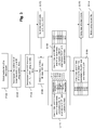
- Fig. 3 shows an algorithm for encoding a digital image according to the invention.
- the algorithm starts at step E100 where the multidimensional digital signal of original samples to decompose is selected.
- the original image IO is selected.
- selection may be made of any of the sub-bands resulting from a previous iteration.
- the selected sub-band LL 0 defines the original resolution for the iteration.
- the following steps E102 and E104 decompose the sub-band LL 0 into the four sub-bands LL 1 , LH 1 , HL 1 and HH 1 , using the conventional mechanisms of filtering as explained above.
- steps E102 and E104 implement the lifting scheme approach for the wavelet transform.
- the convolution method for the wavelet transform may be alternatively used.
- the sub-band LL 0 is decomposed into the intermediate resolution L 1 and H 1 sub-bands by applying a horizontal filtering operation.
- the lifting scheme for the wavelet transform consists in first applying a high-pass filter F to the column of a given parity, for instance the odd columns. A set S1 of filtered samples is thus obtained.
- the filter particularly uses the coefficients (or samples) of the other parity (here even columns), but not the samples of the same parity except the sample to filter.
- the sample in the course of high-pass filtering is the j th coefficient of the line, assuming that the column 0 is the furthest to the left in the image. This sample is denoted x(i,j).
- a filter is applied to the coefficient vector [x(i,j-3),x(i,j-1),x(i,j),x(i,j+1),x(i,j+3)]. This is illustrated by the segment in Fig. 4 .
- LL 0 ' contains the original coefficients at even column locations and the computed coefficients of the high frequency sub-band H 1 of intermediate resolution (i.e. filtered samples) at odd column locations, represented with black dots on the Figure.
- the lifting scheme continues by applying a low-pass filter G to the columns of the other parity (here even columns). Similarly, the filter does not use the samples of the even columns except the sample to filter, and when all the samples have been low-pass filtered, they are replaced in the memory by the filtered values.
- LL 0 contains the coefficients of the low frequency sub-band L 1 at even column locations (cross-hatched dots on the figure) and the coefficients of the high frequency sub-band H 1 of intermediate resolution at odd column locations (black dots on the Figure).
- Step E102 further comprises the de-interleaving of the two sub-bands L 1 and H 1 contained within LL 0 ", by respectively selecting the even and the odd columns. These two sub-bands are stored in memory for future use as explained later.
- these two sub-bands are each decomposed: L 1 into LL 1 and LH 1 sub-bands, and H 1 into HL 1 and HH 1 sub-bands, using the same process but by applying a vertical filtering operation and not a horizontal filtering operation like at step E102.
- the encoder 2 has the four sub-bands LL 1 , LH 1 , HL 1 and HH 1 , as shown in Fig. 2 .
- an oriented transform may be used, such as the mechanisms disclosed in FR-A-2 889 382 .
- the geometric orientations used during the filtering are not saved in memory since, as explained later, the invention provides an independent geometric orientation for the decoding.
- step E106 a calculation of a decoded version of the four lower-resolution sub-bands is performed by simulating all the modifications applied to the data to obtain the decoded version, for example a quantization and a dequantization. Thanks to the decoded version of the sub-bands, the encoder takes into account the losses due to encoding, in particular the quantization, when determining geometric orientations for decoding according to the teachings of the invention.
- this step could simulate any other lossy modification which occurs between the first filtering and the expected inverse filtering of the data at the decoder side, such as the transmission on a noisy channel.
- Sub-band LL 1 represents the coefficients of low frequency (filtered samples) and may be decomposed into another set of sub-bands as explained above.
- sub-band LL 1 is not further decomposed into sub-bands, it is processed like the other sub-bands LH 1 , HL 1 and HH 1 by simulating their actual coding: quantization, entropy coding, entropy decoding and then de-quantization, to obtain modified samples.
- the lossy modification process of step E106 is preferably limited to the simulation of the quantization and the subsequent de-quantization of the coefficients of each sub-band.
- the simulation of quantization and de-quantization consists in simulating the effects of such lossy operations on the coefficients.
- the quantization (or de-quantization) can be scalar quantization as well as vectorial quantization, or any type of quantization.
- more complex coding and decoding lossy algorithms may be simulated instead of solely the quantization and de-quantization.
- the JPEG2000's EBCOT coding and decoding engine may be used.
- a set of modified samples is thus obtained, namely, in the present example, the simulated decoded sub-bands LL 1dec , LH 1dec , HL 1dec and HH 1dec .
- These sub-bands contain decoded filtered samples that should be inverse transformed (i.e. inverse filtered) at the decoder to obtain de-filtered samples.
- sub-band LL 1 is further decomposed into a number of sub-bands LL 2 , LH 2 , HL 2 , HH 2 , etc. of even lower resolution, the following processing steps are performed to obtain the simulated decoded sub-band LL 1dec :
- sub-band LL 1dec may be obtained from other iterations of the steps of Fig. 3 , in particular from the iteration involving the sub-bands LL 2 , LH 2 , HL 2 , HH 2 of even lower resolution as explained later in the present iteration for obtaining LL 0dec .
- step E106 the sub-bands LL 1dec , LH 1dec , HL 1dec and HH 1dec are obtained, which comprise the same decoded filtered values that the decoder would obtain after entropy decoding and de-quantization.
- the following steps, E110 and E130, are particular to the present invention in that they provide the calculation of a geometric orientation for the inverse filters of the decoder. It is remarkable in that this calculation for the decoder is performed during the encoding steps.
- the inverse filters to be applied at the decoder or second filters are taken as the inverse filters of the first filters applied at the encoder.
- the second filters may have different filter coefficients and spatial support compared to the first filters. For example, if the first filter is the 9/7 filter used in the JPEG2000 standard, the second filter may be the 5/3 inverse filter.
- Steps E110 and E130 may be performed successively in any order, or in parallel.
- Step E110 aims at determining the geometric orientations of the inverse filters that the decoder will use when decoding the sub-bands LL 1dec and LH 1dec to reconstruct L 1dec intermediate sub-band. The determination is based on sub-bands LL 1dec , LH 1dec , L 1 and a predetermined criterion.
- a first optional operation is performed on sub-bands LL 1dec , LH 1dec by transposing them (according to the matrix transposition meaning, i.e. by swapping lines and columns of the sub-bands).
- the transposition is noted ' t '. This allows the use of the same horizontal filtering unit for all filtering processes, thus saving on hardware design costs.
- the signals LL 1dec t and LH 1dec t are interleaved (inverse operation to the de-interleaving of step E102) to obtain the L 1 " signal shown in Fig. 5 .
- the black dots of the odd columns represent sub-band LH 1dec and the cross-hatched dots of the even columns represent sub-band LL 1dec .
- step E116 the geometric orientations of the filter G' (inverse filter to G) for each of the values of the L 1 " signal are determined as explained below. These determined orientations are referred to as DL 1G' .
- the L 1 " signal is first filtered with filter G' which is the inverse lifting filter to G. In practice, this is the same filter as G but with all coefficients except the central one multiplied by -1.
- the filter G' may be oriented along a plurality of geometric orientations in the L 1 " signal, for example along three orientations as shown in Fig. 6 .
- Each orientation is associated with an orientation value, for instance a two-bit value representing the values 0 to 2.
- the de-filtered value is calculated for each of the pre-determined geometric orientations by applying filter G' along the corresponding orientations.
- a new set S2 of de-filtered samples is thus obtained, containing, in our example, three values for a same original sample.
- a selection of the most appropriate orientation from among the three possible orientations for the coefficient x(i,j) is therefore made based on a predetermined criterion, the computed values for the coefficient x(i,j) and the original sample at the corresponding position (i,j) in the sub-band L 1 t .
- the distortion between the computed de-filtered value and the original sample is estimated, and the geometric orientation that minimizes the distortion is selected.
- a linear combination of such a distortion with the rate used to encode the orientation may be considered.
- orientation values are stored in memory in the data structure DL 1G' .
- a context function is used to segment the signal L 1 " (or any portion thereof) into different sub-signals.
- a context function applied to a coefficient x(i,j) calculates a value which depends on the coefficients surrounding said coefficient.
- the context function examines the values of the low-frequency sub-band of resolution immediately lower than that of the sub-band currently being filtered, at the positions surrounding the sample of coordinates (i/2, j/2).
- the coordinates (i/2, j/2) are taken to be equal to the integer part below the real value of (i/2, j/2).
- the context function can take only a limited number of values, for example three values. These values are called context values.
- the result is that only three geometric orientation values (which may be the same) are saved in the DL 1G' , one for each sub-signal. Memory is then saved for the storage of DL 1G' .
- context functions are available. A choice of a context function is first made based for example on the function that has the lowest coding cost. This results in an orientation value being saved for each context value for each chosen context function.
- the DL LG' structure then contains the identification of the context function and the orientation values associated with each of the sub-signals.
- the context values may be re-calculated at the decoder side using the identification of the context function and the coefficients of the low-frequency sub-band of resolution immediately lower.
- step E116 the geometric orientations of the inverse filter G' to be applied by the decoder to each decoded filtered coefficient from the coded signal FC are known in the DL 1G' structure.
- Step E116 is followed by step E118 during which the signal L 1 " is filtered along the even columns using filter G' and the determined orientations of DL 1G' .
- the filter G' is oriented according to the geometric orientation set in the DL 1G' structure for the corresponding position (i,j).
- step E116 the de-filtered values computed at step E116 may have been stored temporarily in buffer memory.
- step E118 may consist in retrieving the de-filtered value corresponding to the stored orientation. Buffer memory can then be erased.
- Step E118 thus provides the signal L 1 ' as shown in Fig. 5 .
- step E120 the geometric orientations of the filter F' (inverse filter to F) for each of the values of the L 1 ' signal are determined. These determined orientations are referred to as DL 1F' .
- step E116 is similar to step E116 except that the inverse filtering is performed on signal L 1 ' obtained at step E118 (and not L 1 "), by applying the filter F' (and not G') which is the inverse filter to F.
- F' and not G'
- the filtering is conducted on the coefficients of the odd columns of L 1 ', in order to obtain the geometric orientations in the structure DL 1F' .
- step E122 the signal L 1 ' is filtered along the odd columns using filter F' oriented according the determined orientations of DL 1F' .
- the result of this step is the obtaining of the sub-band L 1 t dec as shown in Fig. 5 .
- This reconstructed sub-band can be expected to substantially correspond to sub-band L 1 t except that the (de)quantization and (de)coding are lossy operations and have added distortion in the image. Thanks to the present invention, this distortion is reduced compared to the known prior art, for similar compression efficiency.
- the sub-band L 1 t dec is transposed in order to recover sub-band L 1dec .
- Fig. 2 shows the relationship between the various sub-bands and the structures DL 1F' and DL 1G' .
- Step E130 is similar to step E110 except that it uses the sub-bands HL 1dec , HH 1dec , and H 1 to determine the geometric orientations of the inverse filters and produce the structures DL 1F' and DH 1G' .
- steps E132-E144 are similar to steps E112-E124.
- step E144 also provides sub-band H 1dec .
- step E150 which is similar to these steps except that it uses the sub-bands L 1dec , H 1dec , obtained at steps E124 and E144, and sub-band LL 0 to determine the geometric orientations of the inverse filters and produce the structures DLL 0F' and DLL 0G' .
- the steps E152-E164 are similar to steps E112-E124.
- step E164 also provides sub-band LL 0dec .
- This sub-band can be reused in a following iteration of the process of Fig. 3 , if LL 0dec does not correspond to the full resolution of the original signal, for example when determining LL 1dec in step E106.
- LL 0dec may not be useful, for example when the iteration is performed on the sub-bands immediately under the original full resolution image.
- the steps E162 and E164 may be avoided to accelerate the process.
- step E150 all the orientations are compressed at step E170.
- the structures DL 1F' , DL 1G' , DH 1F' , DH 1G' , DLL 0F' and DLL 0G' are encoded.
- a single lossless compression such as Huffman coding or arithmetic coding.
- step E172 of quantizing and encoding the sets S3 of de-filtered samples is performed before step E106 to obtain coded filtered samples of the encoded file FC.
- step E172 the sub-bands LH 1 , HL 1 and HH 1 and possibly LL 1 if the latter is not further decomposed into sub-bands of lower resolution are actually encoded.
- step E106 only the de-quantization (and possibly the entropy decoding) is simulated by using the quantized values obtained at this step E172, as represented by the horizontal arrow from box E172 in Fig. 3 .
- the calculation for simulating the quantization is then avoided and processing time is saved.
- step E172 could be performed at any time after step E104.
- the actual coding comprises conventionally quantizing the coefficients of the sub-bands and then entropy coding them, using for example Huffman coding.
- step E174 the coded orientations and sub-bands resulting from steps E170 and E172 are grouped in a same compressed file FC that is subsequently transmitted to the decoder 6.
- the coded orientations and sub-bands may be transmitted separately to the decoder.
- Fig. 2 shows the relationship between the various sub-bands and the structures of orientation information.
- a first step E200 consists in selecting the sub-band to decode, i.e. to reconstruct from sub-bands of lower resolution of the coded file FC.
- the coded sub-bands corresponding to LH 1 , HL 1 and HH 1 obtained from the coded file FC are decoded using conventional means such as inverse quantization (de-quantization) and inverse entropy coding.
- the sub-bands LH 1dec , HL 1dec and HH 1dec of decoded filtered samples are thus obtained.
- step E204 the coded sub-band corresponding to LL 1 obtained from the coded file FC is decoded. Similarly to step E106, two cases are faced.
- the sub-band LL 1dec is decoded using conventional means as at step E202.
- the sub-band is further decomposed into sub-bands of lower resolution during encoding, there is a need for additional steps consisting of decoding sub-bands of lower resolution and recombining them together to obtain LL 1dec .
- the decoding method for the invention or conventional means may be used for recombining the sub-bands of lower resolution.
- the geometric orientations are decoded in order to recover the data structures DL 1F' , DL 1G' , DH 1F' , DH 1G' , DLL 0F' and DLL 0G' .
- step E170 Since the encoding of step E170 is merely conventional, the decoding is also achieved using conventional means, such as entropy decoding.
- this step may involve decoding the context function(s) and the orientations associated with each context value.
- the context functions are then applied at the decoder to obtain the sub-signals corresponding to a given value of the context functions and the orientations retrieved from the data structure of orientations are applied accordingly.
- the steps E202-E206 may be performed in parallel. Alternatively, they may be successive steps in any order.
- steps E208 and E210 consisting in the recombination of sub-bands to obtain respectively sub-bands L 1dec and H 1dec .
- step E208 the sub-bands LL 1dec and LH 1dec are known from steps E202 and E204, as well as the orientation structures DL 1F' and DL 1G' decoded at step E206.
- a similar decoding process to the decoding algorithm disclosed in FR-A-2 889 382 can be used since the orientations for the decoding are known from DL 1F' and DL 1G' .
- step E110 transposition (E112) of LL 1dec and LH 1dec ,interleaving (E114) to obtain L 1 ", filtering (E118) using DL 1G' , filtering (E122) using DL 1F' , and transposition (E124) to recover sub-band L 1dec .
- Step E210 is similar to step E208, except that it uses the sub-bands HL 1dec and HH 1dec , and the orientation structures DL 1F' and DH 1G' .
- Step E210 produces sub-band H 1dec .
- step E212 is also similar to these steps, except that it uses the sub-bands L 1dec and H 1dec from the steps E208 and E210, and the orientation structures DLL 0F' and DLL 0G' decoded at step E206.
- Step E212 produces sub-band LL 0dec .
- Another iteration may also be performed using this decoded sub-band LL 0dec in order to decode a higher resolution sub-band.
- the filter orientations for the decoding are determined during the coding of the image. This enables fast decoding, since at the decoding stage, the orientations are pre-determined.
- this pre-determination takes into account the decoded image (using simulation) and the original image. It results in optimization of the choice of the orientations for the decoding to minimize the distortion of the coding/decoding.
- the invention is particularly efficient since it may be used with any filter, in particular the best Rate/Distortion filters such as 9/7.
- the invention is compatible with conventional decoding such as JPEG2000, provided that the information on geometric orientations is stored in metadata.
- An information processing device implementing the present invention is for example a micro-computer 40, a workstation, a personal assistant, or a mobile telephone connected to different peripherals.
- the information processing device takes the form of a camera provided with a communication interface to enable connection to a network.
- the peripherals connected to the information processing device comprise for example a digital camera 60, or a scanner or a camcorder or any other means of image acquisition or storage, connected to an input/output graphics card (not shown) and supplying multimedia data to the information processing device.
- the peripherals may also comprise a microphone 62 by means of an input/output card (not shown).
- the device 40 comprises a communication bus 41 to which there are connected:
- the communication bus 41 permits communication and interoperability between the different elements included in the device 40 or connected to it.
- the representation of the bus 41 is non-limiting and, in particular, the central processing unit 42 unit may communicate instructions to any element of the device 40 directly or by means of another element of the device 40.
- the external disks 70 can be any information carrier such as a compact disc (CD-ROM) rewritable or not, a ZIP disk or a memory card.
- CD-ROM compact disc
- an information storage means which can be read by a micro-computer or microprocessor, integrated or not into the information processing device, and which may possibly be removable, is adapted to store one or more programs whose execution permits the implementation of the method according to the invention.
- the executable code enabling the information processing device to implement the invention may equally well be stored in read only memory 43, on the hard disk 48 or on a removable digital medium such as an external disk 70 as described earlier.
- the executable code of the programs is received by the intermediary of the telecommunications network 80, via the interface 50, to be stored in one of the storage means of the device 40 (such as the hard disk 48) before being executed.
- the central processing unit 42 controls and directs the execution of the instructions or portions of software code of the program or programs of the invention, the instructions or portions of software code being stored in one of the aforementioned storage means.
- the program or programs which are stored in a non-volatile memory for example the hard disk 48 or the read only memory 43, are transferred into the random-access memory 44, which then contains the executable code of the program or programs of the invention, as well as registers for storing the variables and parameters necessary for implementation of the invention.
- the device implementing the invention or incorporating it may also be implemented in the form of a programmed apparatus.
- a device may then contain the code of the computer program(s) in a fixed form in an application specific integrated circuit (ASIC).
- ASIC application specific integrated circuit
- the device described here and, particularly, the central processing unit 42, may implement all or part of the processing operations described in relation to Fig. 1 to 7 , to implement the coding method of the present invention and constitute the coding device of the present invention.
- the second filters F' and G' of steps E110, E130 and E150 are inverse filters of the first filters F and G used in step E102
- any independent filter may be used for the decoding, providing that the coder 2 knows it in order to correctly determine the suitable geometric orientation for best rendering.
- the coder may inform the decoder of the second filters used at steps E110 and E130, for example by sending the filter coefficients in a metadata field of the digital signal coding format, along with the orientation data structures.
- step E102 The use of different filters for step E102 and the decoding is of particular interest, since a different decoding filter may provide a better reconstruction quality at similar rate.
- the invention makes it possible since the determination of the geometric orientation is independent from the filters used in step E102 of decomposition.
Landscapes
- Engineering & Computer Science (AREA)
- Multimedia (AREA)
- Signal Processing (AREA)
- Physics & Mathematics (AREA)
- Discrete Mathematics (AREA)
- General Physics & Mathematics (AREA)
- Compression Or Coding Systems Of Tv Signals (AREA)
- Compression, Expansion, Code Conversion, And Decoders (AREA)
Claims (16)
- Procédé de codage d'un signal numérique multidimensionnel (IO, LL0) comprenant une pluralité d'échantillons originaux, pour former un flux codé (FC), le procédé comprenant :- une étape de filtrage (E102) des échantillons originaux en appliquant au moins un premier filtre (F, G) le long d'une première orientation géométrique, pour obtenir des échantillons filtrés (L1, H1, LL1, LH1, HL1, HH1) et- une étape de codage (E172) d'au moins certains desdits échantillons filtrés pour obtenir des échantillons filtrés codés correspondants adaptés pour être décodés, par un décodeur, en échantillons filtrés décodés,
le procédé comprenant en outre les étapes suivantes :- application (E106) d'une modification avec perte aux échantillons filtrés pour obtenir des échantillons modifiés (L1dec, H1dec, LL1dec, LH1dec, HL1dex, HH1dec) ;- détermination (E110, E130, E150), parmi une pluralité de deuxièmes orientations géométriques, d'au moins une orientation géométrique d'un deuxième filtre (F', G') devant être appliquée par le décodeur à au moins un échantillon filtré décodé, où la détermination minimise un critère relatif à la distorsion entre les échantillons originaux et les échantillons modifiés filtrés en utilisant les deuxièmes orientations géométriques, et- fourniture (E174) desdites orientations géométriques déterminées (DL1F', DL1G', DH1F', DH1G' DLL0F', DLL0G') et desdits échantillons filtrés codés au décodeur ;
le procédé étant caractérisé en ce que la détermination est indépendante de la première orientation géométrique utilisée pour filtrer les échantillons originaux. - Procédé selon la revendication 1, dans lequel ladite étape d'application (E106) comprend le fait de réaliser, sur les échantillons filtrés, une quantification, et de réaliser une déquantification correspondante des échantillons filtrés quantifiés, pour obtenir les échantillons modifiés.
- Procédé selon la revendication 1, dans lequel ladite étape d'application (E106) comprend le fait de décomposer les échantillons filtrés (LL1) en sous-bandes (LL2, LH2, HL2, HH2), de réaliser, sur les échantillons filtrés de toutes les sous-bandes, une quantification, et de réaliser une déquantification correspondante des échantillons quantifiés, et de reconstruire lesdits échantillons modifiés (LL1dec) à partir des échantillons déquantifiés (LL2dec, LH2dec, HL2dec, HH2dec).
- Procédé selon la revendication 1, dans lequel l'étape de codage (E172) des échantillons filtrés comprend une étape de quantification des échantillons filtrés, et l'étape d'application (E106) comprend la réalisation d'une déquantification des échantillons filtrés quantifiés.
- Procédé selon l'une des revendications 1 à 4, dans lequel ladite détermination (E110, E130, E150) comprend, pour au moins un échantillon modifié, les étapes suivantes :- réalisation du filtrage de l'échantillon modifié en appliquant le deuxième filtre (F', G') à celui-ci dans une pluralité d'orientations géométriques, la réalisation résultant en une pluralité d'échantillons modifiés filtrés correspondants ;- sélection de l'une desdites orientations géométriques en fonction du critère de minimisation relatif à la distorsion entre les échantillons modifiés filtrés et les échantillons originaux.
- Procédé selon la revendication précédente, dans lequel l'orientation géométrique sélectionnée en fonction du critère de minimisation est l'orientation géométrique associée à l'échantillon modifié filtré qui minimise la distorsion par rapport au signal multidimensionnel original.
- Procédé selon l'une des revendications 1 à 6, comprenant le filtrage (E118, E122, E138, E142, E158, E162) d'échantillons modifiés, de manière à obtenir des échantillons modifiés filtrés correspondant à un signal multidimensionnel avec une résolution plus élevée.
- Procédé selon la revendication précédente lorsqu'elle dépend de la revendication 5, dans lequel ledit filtrage (E118, E122, E138, E142, E158, E162) des échantillons modifiés comprend la récupération, à partir des pluralités d'échantillons modifiés filtrés, des échantillons modifiés filtrés correspondant aux orientations géométriques sélectionnées.
- Procédé selon l'une des revendications 1 à 4, dans lequel ladite détermination (E110, E130, E150) comprend les étapes suivantes :- calcul, pour chaque échantillon modifié, de la valeur d'une fonction, dite fonction de contexte, qui tient compte d'un nombre prédéterminé d'autres échantillons modifiés entourant l'échantillon modifié considéré ;- division des échantillons modifiés en sous-signaux, chacun correspondant aux différentes valeurs prises par la fonction de contexte ;- association d'une même orientation géométrique du deuxième filtre (F', G') avec les échantillons filtrés correspondant à tous les échantillons modifiés d'un même sous-signal.
- Procédé selon l'une des revendications 1 à 9, comprenant le codage (E170) d'informations représentant les orientations géométriques déterminées pour former une partie du flux codé (FC).
- Procédé selon l'une des revendications 1 à 10, dans lequel l'au moins un premier filtre (F, G) est appliqué avec la même orientation pour le filtrage de chaque échantillon original.
- Procédé selon l'une des revendications 1 à 10, dans lequel l'étape de filtrage (E102) d'un échantillon original comprend la détermination, en fonction d'au moins un autre critère de minimisation relatif à la distorsion, d'une orientation géométrique parmi une pluralité d'orientations géométriques dans le signal numérique multidimensionnel, et le filtrage dudit échantillon original en appliquant l'au moins un premier filtre (F, G) avec l'orientation géométrique déterminée.
- Procédé selon l'une des revendications précédentes, dans lequel les étapes de filtrage (E102), de détermination (E110, E130, E150) et de fourniture (E174) sont itérées de manière à décomposer ledit signal numérique (IO, LL0) en sous-bandes (L1, H1, LL1, LH1, HL1, HH1).
- Dispositif de codage d'un signal numérique multidimensionnel (IO, LL0) comprenant une pluralité d'échantillons originaux pour former un flux codé (FC), le dispositif comprenant un moyen de filtrage pour filtrer des échantillons originaux en appliquant au moins un premier filtre (F, G) le long d'une première orientation géométrique, pour obtenir des échantillons filtrés (L1, H1, LL1, LH1, HL1, HH1) et un moyen de codage pour coder au moins certains desdits échantillons filtrés pour obtenir des échantillons filtrés codés correspondants adaptés pour être décodés, par un décodeur, en échantillons filtrés décodés, le dispositif comprenant :- un moyen de modification pour appliquer une modification avec perte aux échantillons filtrés pour obtenir des échantillons modifiés (Lidec, H1dec, LL1dec, LH1dec, HL1dec, HH1dec) ;- un moyen de détermination pour déterminer, parmi une pluralité de deuxièmes orientations géométriques, au moins une orientation géométrique d'un deuxième filtre (F', G') devant être appliquée par le décodeur à au moins un échantillon filtré décodé, où la détermination minimise un critère relatif à la distorsion entre les échantillons originaux et les échantillons modifiés filtrés en utilisant les deuxièmes orientations géométriques, et- un moyen de fourniture pour fournir lesdites orientations géométriques déterminées et lesdits échantillons filtrés codés au décodeur,
le dispositif étant caractérisé en ce que le moyen de détermination est configuré de sorte que la détermination soit indépendante de la première orientation géométrique utilisée pour filtrer les échantillons originaux. - Moyen de stockage d'informations qui est lisible par un système informatique, comprenant des instructions pour un programme informatique conçu pour mettre en oeuvre le procédé selon l'une quelconque des revendications 1 à 13 lorsque le programme est chargé et exécuté par le système informatique.
- Produit de programme informatique pouvant être lu par un microprocesseur, comprenant des parties de code de logiciel conçu pour mettre en oeuvre le procédé selon l'une quelconque des revendications 1 à 13 lorsqu'il est chargé et exécuté par le microprocesseur.
Priority Applications (3)
| Application Number | Priority Date | Filing Date | Title |
|---|---|---|---|
| EP09305826.1A EP2299716B1 (fr) | 2009-09-09 | 2009-09-09 | Procédé et dispositif pour le codage d'un signal numérique multidimensionnel |
| PCT/IB2010/054078 WO2011030304A1 (fr) | 2009-09-09 | 2010-09-09 | Procédé et dispositif de codage d'un signal numérique multidimensionnel |
| US13/394,050 US8989278B2 (en) | 2009-09-09 | 2010-09-09 | Method and device for coding a multi dimensional digital signal comprising original samples to form coded stream |
Applications Claiming Priority (1)
| Application Number | Priority Date | Filing Date | Title |
|---|---|---|---|
| EP09305826.1A EP2299716B1 (fr) | 2009-09-09 | 2009-09-09 | Procédé et dispositif pour le codage d'un signal numérique multidimensionnel |
Publications (2)
| Publication Number | Publication Date |
|---|---|
| EP2299716A1 EP2299716A1 (fr) | 2011-03-23 |
| EP2299716B1 true EP2299716B1 (fr) | 2016-11-23 |
Family
ID=41328964
Family Applications (1)
| Application Number | Title | Priority Date | Filing Date |
|---|---|---|---|
| EP09305826.1A Not-in-force EP2299716B1 (fr) | 2009-09-09 | 2009-09-09 | Procédé et dispositif pour le codage d'un signal numérique multidimensionnel |
Country Status (3)
| Country | Link |
|---|---|
| US (1) | US8989278B2 (fr) |
| EP (1) | EP2299716B1 (fr) |
| WO (1) | WO2011030304A1 (fr) |
Families Citing this family (4)
| Publication number | Priority date | Publication date | Assignee | Title |
|---|---|---|---|---|
| EP2299716B1 (fr) | 2009-09-09 | 2016-11-23 | Canon Kabushiki Kaisha | Procédé et dispositif pour le codage d'un signal numérique multidimensionnel |
| EP2398240A1 (fr) * | 2010-06-16 | 2011-12-21 | Canon Kabushiki Kaisha | Procédé et dispositif pour le codage et le décodage d'un signal vidéo |
| EP3499885B1 (fr) | 2017-12-18 | 2024-07-17 | Canon Kabushiki Kaisha | Procédé et dispositif de codage de données vidéo |
| EP3499886B1 (fr) | 2017-12-18 | 2025-02-12 | Canon Kabushiki Kaisha | Procédé et dispositif de codage de données vidéo |
Family Cites Families (39)
| Publication number | Priority date | Publication date | Assignee | Title |
|---|---|---|---|---|
| FR2750280A1 (fr) | 1996-06-21 | 1997-12-26 | Canon Kk | Transmission progressive d'image numerique |
| FR2755818A1 (fr) | 1996-11-08 | 1998-05-15 | Canon Kk | Codage de signal numerique par decomposition en sous-bandes de frequence et quantification vectorielle a etats finis |
| US6353680B1 (en) * | 1997-06-30 | 2002-03-05 | Intel Corporation | Method and apparatus for providing image and video coding with iterative post-processing using a variable image model parameter |
| US6498866B2 (en) | 1997-08-29 | 2002-12-24 | Canon Kabushiki Kaisha | Methods and devices for processing data and notably for compressing and decompressing images |
| EP0899960A3 (fr) | 1997-08-29 | 1999-06-09 | Canon Kabushiki Kaisha | Codage et décodage de signaux numériques |
| US6501860B1 (en) | 1998-01-19 | 2002-12-31 | Canon Kabushiki Kaisha | Digital signal coding and decoding based on subbands |
| FR2782861A1 (fr) | 1998-08-26 | 2000-03-03 | Canon Kk | Transcodage geometrique d'un signal numerique |
| EP1032216A1 (fr) | 1999-02-24 | 2000-08-30 | Canon Kabushiki Kaisha | Dispositif et procédé pour la transformation d'un signal numérique |
| FR2792151B1 (fr) | 1999-04-08 | 2004-04-30 | Canon Kk | Procedes et dispositifs de codage et de decodage de signaux numeriques, et systemes les mettant en oeuvre |
| FR2792150B1 (fr) | 1999-04-08 | 2003-02-28 | Canon Kk | Procedes et dispositis de codage et de decodage de signaux numeriques, et systemes les mettant en oeuvre |
| EP1109409A3 (fr) | 1999-12-17 | 2011-11-30 | Canon Kabushiki Kaisha | Codage de signal numérique avec division en tuiles |
| FR2809248B1 (fr) | 2000-05-19 | 2003-08-08 | Canon Kk | Compression de donnees numeriques et codage des donnees compressees pour les proteger contre les erreurs de transmission |
| JP4710108B2 (ja) * | 2000-07-14 | 2011-06-29 | ソニー株式会社 | 画像信号符号化方法及び装置 |
| US7460722B2 (en) | 2002-01-11 | 2008-12-02 | Canon Kabushiki Kaisha | Encoding of digital data with determination of sample path |
| WO2003103178A1 (fr) * | 2002-05-29 | 2003-12-11 | Pixonics, Inc. | Codage video par interpolation |
| FR2846835B1 (fr) | 2002-11-05 | 2005-04-15 | Canon Kk | Codage de donnees numeriques combinant plusieurs modes de codage |
| US7463782B2 (en) | 2002-11-05 | 2008-12-09 | Canon Kabushiki Kaisha | Data encoding with an amplitude model and path between the data and corresponding decoding |
| FR2849982B1 (fr) | 2003-01-15 | 2005-04-08 | Canon Kk | Decodage d'une image numerique codee selon plusieurs niveaux de resolution |
| CA2499163A1 (fr) * | 2004-03-03 | 2005-09-03 | Her Majesty The Queen In Right Of Canada, As Represented By The Minister Of Industry, Through The Communication Research Centre Canada | Transformee en ondelettes le long d'une courbe pour la compression image et video |
| FR2875042B1 (fr) | 2004-09-03 | 2006-11-24 | Canon Kk | Procede et dispositif d'acces aleatoire a une zone d'une image codee en vue de la decoder et procede et dispositif de codage d'une image |
| US7936938B2 (en) | 2004-09-07 | 2011-05-03 | Canon Kabushiki Kaisha | Methods and devices for encoding a digital image signal and associated decoding methods and devices |
| KR100703788B1 (ko) * | 2005-06-10 | 2007-04-06 | 삼성전자주식회사 | 스무딩 예측을 이용한 다계층 기반의 비디오 인코딩 방법,디코딩 방법, 비디오 인코더 및 비디오 디코더 |
| FR2889382A1 (fr) | 2005-07-29 | 2007-02-02 | Canon Res Ct France Soc Par Ac | Procede et dispositif de filtrage d'un signal numerique multidimensionnel et procedes et dispositifs de codage et decodage associes |
| US20070116373A1 (en) * | 2005-11-23 | 2007-05-24 | Sonosite, Inc. | Multi-resolution adaptive filtering |
| FR2898757A1 (fr) | 2006-03-14 | 2007-09-21 | Canon Kk | Procede et dispositif d'adaptation d'une frequence temporelle d'une sequence d'images video |
| US8189934B2 (en) | 2006-03-27 | 2012-05-29 | Panasonic Corporation | Image coding apparatus and image decoding apparatus |
| EP1845729A1 (fr) * | 2006-04-12 | 2007-10-17 | Matsushita Electric Industrial Co., Ltd. | Transmission d'algorithmes d'optimisation post-filtre |
| FR2903556B1 (fr) | 2006-07-04 | 2008-10-03 | Canon Kk | Procedes et des dispositifs de codage et de decodage d'images, un systeme de telecommunications comportant de tels dispositifs et des programmes d'ordinateur mettant en oeuvre de tels procedes |
| FR2906093A1 (fr) | 2006-09-18 | 2008-03-21 | Canon Kk | Procedes et dispositifs de codage et de decodage, systeme de telecommunication et programme d'ordinateur les mettant en oeuvre |
| US8249372B2 (en) | 2007-03-16 | 2012-08-21 | Canon Kabushiki Kaisha | Methods and devices for coding and decoding multidimensional digital signals |
| FR2919779B1 (fr) | 2007-08-02 | 2010-02-26 | Canon Kk | Procede et dispositif de codage avec perte d'un signal numerique |
| FR2927744B1 (fr) * | 2008-02-20 | 2012-09-21 | Canon Kk | Procede et dispositif de filtrage d'un signal numerique. |
| US8588539B2 (en) * | 2008-02-20 | 2013-11-19 | Canon Kabushiki Kaisha | Methods and devices for filtering and coding a digital signal |
| FR2927745B1 (fr) | 2008-02-20 | 2010-06-18 | Canon Kk | Procede et dispositif de codage d'un signal numerique. |
| FR2929431B1 (fr) | 2008-03-26 | 2010-12-03 | Canon Kk | Procede et dispositif de classification des echantillons representatifs d'un signal numerique d'image |
| FR2929787B1 (fr) | 2008-04-04 | 2010-12-17 | Canon Kk | Procede et dispositif de traitement d'un flux de donnees |
| US20120117133A1 (en) | 2009-05-27 | 2012-05-10 | Canon Kabushiki Kaisha | Method and device for processing a digital signal |
| EP2299716B1 (fr) | 2009-09-09 | 2016-11-23 | Canon Kabushiki Kaisha | Procédé et dispositif pour le codage d'un signal numérique multidimensionnel |
| WO2011036653A1 (fr) | 2009-09-28 | 2011-03-31 | Canon Kabushiki Kaisha | Procedes et dispositifs de filtrage et de codage d'un signal numerique |
-
2009
- 2009-09-09 EP EP09305826.1A patent/EP2299716B1/fr not_active Not-in-force
-
2010
- 2010-09-09 US US13/394,050 patent/US8989278B2/en not_active Expired - Fee Related
- 2010-09-09 WO PCT/IB2010/054078 patent/WO2011030304A1/fr not_active Ceased
Also Published As
| Publication number | Publication date |
|---|---|
| US8989278B2 (en) | 2015-03-24 |
| US20120155749A1 (en) | 2012-06-21 |
| WO2011030304A1 (fr) | 2011-03-17 |
| EP2299716A1 (fr) | 2011-03-23 |
Similar Documents
| Publication | Publication Date | Title |
|---|---|---|
| US6711299B2 (en) | Wavelet transformation of dithered quantized/reduced color pixels for color bit depth image compression and decompression | |
| CN100568969C (zh) | 可逆子波变换和嵌入代码流处理方法 | |
| US6101279A (en) | Image compression system using block transforms and tree-type coefficient truncation | |
| US5802481A (en) | Adaptive filtering for use with data compression and signal reconstruction | |
| US6347157B2 (en) | System and method for encoding a video sequence using spatial and temporal transforms | |
| US7577308B2 (en) | Image data generation with reduced amount of processing | |
| US20100008592A1 (en) | Image signal transforming and inverse-transforming method and computer program product with pre-encoding filtering features | |
| US20070237412A1 (en) | Image encoding apparatus and image decoding apparatus | |
| WO2007030788A2 (fr) | Codage et decodage de poursuites adaptatives par ondelettes a dimension reduite | |
| US20050031218A1 (en) | Tile boundary artifact removal for arbitrary wavelet filters | |
| JP4718609B2 (ja) | 多次元デジタル信号のフィルタリング方法及び装置、並びに、関連する符号化/復号化方法及び装置 | |
| EP2299716B1 (fr) | Procédé et dispositif pour le codage d'un signal numérique multidimensionnel | |
| WO2008035223A2 (fr) | Procédés et dispositifs de codage et de décodage, système de télécommunications et programme d'ordinateur mettant en oeuvre ces derniers | |
| Chew et al. | Very low-memory wavelet compression architecture using strip-based processing for implementation in wireless sensor networks | |
| KR20220019285A (ko) | 프레임들의 시퀀스를 인코딩하는 방법 및 인코더 | |
| US8588539B2 (en) | Methods and devices for filtering and coding a digital signal | |
| Abdul-Wahed et al. | Compression of image using multi-wavelet techniques | |
| JP4806464B2 (ja) | 画像圧縮装置、画像圧縮方法、画像復元装置、及びプログラム | |
| JP2007049485A (ja) | 離散ウェーブレット変換装置及び方法、並びにプログラム及び記録媒体 | |
| JP5351093B2 (ja) | 画像符号化方法,画像符号化装置および画像符号化プログラム | |
| Sevcenco et al. | Combined adaptive and averaging strategies for JPEG-based low bit-rate image coding | |
| Shi | For the degree of Master of Science in Computer Science | |
| EP0847651A1 (fr) | Procede et circuit de traitement d'images | |
| Ramstad | Lossless Subband Image Compression Using Integer Coefficient Filter Banks | |
| HK1015996A (en) | Adaptive filtering for use with data compression and signal reconstruction |
Legal Events
| Date | Code | Title | Description |
|---|---|---|---|
| PUAI | Public reference made under article 153(3) epc to a published international application that has entered the european phase |
Free format text: ORIGINAL CODE: 0009012 |
|
| AK | Designated contracting states |
Kind code of ref document: A1 Designated state(s): AT BE BG CH CY CZ DE DK EE ES FI FR GB GR HR HU IE IS IT LI LT LU LV MC MK MT NL NO PL PT RO SE SI SK SM TR |
|
| AX | Request for extension of the european patent |
Extension state: AL BA RS |
|
| 17P | Request for examination filed |
Effective date: 20110913 |
|
| 17Q | First examination report despatched |
Effective date: 20121008 |
|
| REG | Reference to a national code |
Ref country code: DE Ref legal event code: R079 Ref document number: 602009042575 Country of ref document: DE Free format text: PREVIOUS MAIN CLASS: H04N0007260000 Ipc: H04N0019460000 |
|
| GRAP | Despatch of communication of intention to grant a patent |
Free format text: ORIGINAL CODE: EPIDOSNIGR1 |
|
| RIC1 | Information provided on ipc code assigned before grant |
Ipc: H04N 19/122 20140101ALI20160524BHEP Ipc: H04N 19/11 20140101ALI20160524BHEP Ipc: H04N 19/46 20140101AFI20160524BHEP Ipc: H04N 19/117 20140101ALI20160524BHEP Ipc: H04N 19/14 20140101ALI20160524BHEP Ipc: H04N 19/147 20140101ALI20160524BHEP Ipc: H04N 19/172 20140101ALI20160524BHEP Ipc: H04N 19/635 20140101ALI20160524BHEP Ipc: H04N 19/463 20140101ALI20160524BHEP |
|
| INTG | Intention to grant announced |
Effective date: 20160606 |
|
| GRAS | Grant fee paid |
Free format text: ORIGINAL CODE: EPIDOSNIGR3 |
|
| GRAA | (expected) grant |
Free format text: ORIGINAL CODE: 0009210 |
|
| AK | Designated contracting states |
Kind code of ref document: B1 Designated state(s): AT BE BG CH CY CZ DE DK EE ES FI FR GB GR HR HU IE IS IT LI LT LU LV MC MK MT NL NO PL PT RO SE SI SK SM TR |
|
| REG | Reference to a national code |
Ref country code: GB Ref legal event code: FG4D |
|
| REG | Reference to a national code |
Ref country code: CH Ref legal event code: EP |
|
| REG | Reference to a national code |
Ref country code: IE Ref legal event code: FG4D |
|
| REG | Reference to a national code |
Ref country code: AT Ref legal event code: REF Ref document number: 848830 Country of ref document: AT Kind code of ref document: T Effective date: 20161215 |
|
| REG | Reference to a national code |
Ref country code: DE Ref legal event code: R096 Ref document number: 602009042575 Country of ref document: DE |
|
| PG25 | Lapsed in a contracting state [announced via postgrant information from national office to epo] |
Ref country code: LV Free format text: LAPSE BECAUSE OF FAILURE TO SUBMIT A TRANSLATION OF THE DESCRIPTION OR TO PAY THE FEE WITHIN THE PRESCRIBED TIME-LIMIT Effective date: 20161123 |
|
| REG | Reference to a national code |
Ref country code: LT Ref legal event code: MG4D |
|
| REG | Reference to a national code |
Ref country code: NL Ref legal event code: MP Effective date: 20161123 |
|
| REG | Reference to a national code |
Ref country code: AT Ref legal event code: MK05 Ref document number: 848830 Country of ref document: AT Kind code of ref document: T Effective date: 20161123 |
|
| PG25 | Lapsed in a contracting state [announced via postgrant information from national office to epo] |
Ref country code: LT Free format text: LAPSE BECAUSE OF FAILURE TO SUBMIT A TRANSLATION OF THE DESCRIPTION OR TO PAY THE FEE WITHIN THE PRESCRIBED TIME-LIMIT Effective date: 20161123 Ref country code: NL Free format text: LAPSE BECAUSE OF FAILURE TO SUBMIT A TRANSLATION OF THE DESCRIPTION OR TO PAY THE FEE WITHIN THE PRESCRIBED TIME-LIMIT Effective date: 20161123 Ref country code: GR Free format text: LAPSE BECAUSE OF FAILURE TO SUBMIT A TRANSLATION OF THE DESCRIPTION OR TO PAY THE FEE WITHIN THE PRESCRIBED TIME-LIMIT Effective date: 20170224 Ref country code: SE Free format text: LAPSE BECAUSE OF FAILURE TO SUBMIT A TRANSLATION OF THE DESCRIPTION OR TO PAY THE FEE WITHIN THE PRESCRIBED TIME-LIMIT Effective date: 20161123 Ref country code: NO Free format text: LAPSE BECAUSE OF FAILURE TO SUBMIT A TRANSLATION OF THE DESCRIPTION OR TO PAY THE FEE WITHIN THE PRESCRIBED TIME-LIMIT Effective date: 20170223 |
|
| PG25 | Lapsed in a contracting state [announced via postgrant information from national office to epo] |
Ref country code: PT Free format text: LAPSE BECAUSE OF FAILURE TO SUBMIT A TRANSLATION OF THE DESCRIPTION OR TO PAY THE FEE WITHIN THE PRESCRIBED TIME-LIMIT Effective date: 20170323 Ref country code: ES Free format text: LAPSE BECAUSE OF FAILURE TO SUBMIT A TRANSLATION OF THE DESCRIPTION OR TO PAY THE FEE WITHIN THE PRESCRIBED TIME-LIMIT Effective date: 20161123 Ref country code: HR Free format text: LAPSE BECAUSE OF FAILURE TO SUBMIT A TRANSLATION OF THE DESCRIPTION OR TO PAY THE FEE WITHIN THE PRESCRIBED TIME-LIMIT Effective date: 20161123 Ref country code: PL Free format text: LAPSE BECAUSE OF FAILURE TO SUBMIT A TRANSLATION OF THE DESCRIPTION OR TO PAY THE FEE WITHIN THE PRESCRIBED TIME-LIMIT Effective date: 20161123 Ref country code: FI Free format text: LAPSE BECAUSE OF FAILURE TO SUBMIT A TRANSLATION OF THE DESCRIPTION OR TO PAY THE FEE WITHIN THE PRESCRIBED TIME-LIMIT Effective date: 20161123 Ref country code: AT Free format text: LAPSE BECAUSE OF FAILURE TO SUBMIT A TRANSLATION OF THE DESCRIPTION OR TO PAY THE FEE WITHIN THE PRESCRIBED TIME-LIMIT Effective date: 20161123 |
|
| PG25 | Lapsed in a contracting state [announced via postgrant information from national office to epo] |
Ref country code: CZ Free format text: LAPSE BECAUSE OF FAILURE TO SUBMIT A TRANSLATION OF THE DESCRIPTION OR TO PAY THE FEE WITHIN THE PRESCRIBED TIME-LIMIT Effective date: 20161123 Ref country code: RO Free format text: LAPSE BECAUSE OF FAILURE TO SUBMIT A TRANSLATION OF THE DESCRIPTION OR TO PAY THE FEE WITHIN THE PRESCRIBED TIME-LIMIT Effective date: 20161123 Ref country code: EE Free format text: LAPSE BECAUSE OF FAILURE TO SUBMIT A TRANSLATION OF THE DESCRIPTION OR TO PAY THE FEE WITHIN THE PRESCRIBED TIME-LIMIT Effective date: 20161123 Ref country code: SK Free format text: LAPSE BECAUSE OF FAILURE TO SUBMIT A TRANSLATION OF THE DESCRIPTION OR TO PAY THE FEE WITHIN THE PRESCRIBED TIME-LIMIT Effective date: 20161123 Ref country code: DK Free format text: LAPSE BECAUSE OF FAILURE TO SUBMIT A TRANSLATION OF THE DESCRIPTION OR TO PAY THE FEE WITHIN THE PRESCRIBED TIME-LIMIT Effective date: 20161123 |
|
| REG | Reference to a national code |
Ref country code: DE Ref legal event code: R097 Ref document number: 602009042575 Country of ref document: DE |
|
| PG25 | Lapsed in a contracting state [announced via postgrant information from national office to epo] |
Ref country code: BE Free format text: LAPSE BECAUSE OF FAILURE TO SUBMIT A TRANSLATION OF THE DESCRIPTION OR TO PAY THE FEE WITHIN THE PRESCRIBED TIME-LIMIT Effective date: 20161123 Ref country code: SM Free format text: LAPSE BECAUSE OF FAILURE TO SUBMIT A TRANSLATION OF THE DESCRIPTION OR TO PAY THE FEE WITHIN THE PRESCRIBED TIME-LIMIT Effective date: 20161123 Ref country code: BG Free format text: LAPSE BECAUSE OF FAILURE TO SUBMIT A TRANSLATION OF THE DESCRIPTION OR TO PAY THE FEE WITHIN THE PRESCRIBED TIME-LIMIT Effective date: 20170223 Ref country code: IT Free format text: LAPSE BECAUSE OF FAILURE TO SUBMIT A TRANSLATION OF THE DESCRIPTION OR TO PAY THE FEE WITHIN THE PRESCRIBED TIME-LIMIT Effective date: 20161123 |
|
| PLBE | No opposition filed within time limit |
Free format text: ORIGINAL CODE: 0009261 |
|
| STAA | Information on the status of an ep patent application or granted ep patent |
Free format text: STATUS: NO OPPOSITION FILED WITHIN TIME LIMIT |
|
| 26N | No opposition filed |
Effective date: 20170824 |
|
| PG25 | Lapsed in a contracting state [announced via postgrant information from national office to epo] |
Ref country code: SI Free format text: LAPSE BECAUSE OF FAILURE TO SUBMIT A TRANSLATION OF THE DESCRIPTION OR TO PAY THE FEE WITHIN THE PRESCRIBED TIME-LIMIT Effective date: 20161123 |
|
| PGFP | Annual fee paid to national office [announced via postgrant information from national office to epo] |
Ref country code: DE Payment date: 20171130 Year of fee payment: 9 |
|
| REG | Reference to a national code |
Ref country code: CH Ref legal event code: PL |
|
| GBPC | Gb: european patent ceased through non-payment of renewal fee |
Effective date: 20170909 |
|
| PG25 | Lapsed in a contracting state [announced via postgrant information from national office to epo] |
Ref country code: MC Free format text: LAPSE BECAUSE OF FAILURE TO SUBMIT A TRANSLATION OF THE DESCRIPTION OR TO PAY THE FEE WITHIN THE PRESCRIBED TIME-LIMIT Effective date: 20161123 |
|
| REG | Reference to a national code |
Ref country code: IE Ref legal event code: MM4A |
|
| PG25 | Lapsed in a contracting state [announced via postgrant information from national office to epo] |
Ref country code: LU Free format text: LAPSE BECAUSE OF NON-PAYMENT OF DUE FEES Effective date: 20170909 |
|
| REG | Reference to a national code |
Ref country code: FR Ref legal event code: ST Effective date: 20180531 |
|
| PG25 | Lapsed in a contracting state [announced via postgrant information from national office to epo] |
Ref country code: GB Free format text: LAPSE BECAUSE OF NON-PAYMENT OF DUE FEES Effective date: 20170909 Ref country code: LI Free format text: LAPSE BECAUSE OF NON-PAYMENT OF DUE FEES Effective date: 20170930 Ref country code: CH Free format text: LAPSE BECAUSE OF NON-PAYMENT OF DUE FEES Effective date: 20170930 Ref country code: IE Free format text: LAPSE BECAUSE OF NON-PAYMENT OF DUE FEES Effective date: 20170909 |
|
| PG25 | Lapsed in a contracting state [announced via postgrant information from national office to epo] |
Ref country code: FR Free format text: LAPSE BECAUSE OF NON-PAYMENT OF DUE FEES Effective date: 20171002 |
|
| PG25 | Lapsed in a contracting state [announced via postgrant information from national office to epo] |
Ref country code: MT Free format text: LAPSE BECAUSE OF NON-PAYMENT OF DUE FEES Effective date: 20170909 |
|
| REG | Reference to a national code |
Ref country code: DE Ref legal event code: R119 Ref document number: 602009042575 Country of ref document: DE |
|
| PG25 | Lapsed in a contracting state [announced via postgrant information from national office to epo] |
Ref country code: HU Free format text: LAPSE BECAUSE OF FAILURE TO SUBMIT A TRANSLATION OF THE DESCRIPTION OR TO PAY THE FEE WITHIN THE PRESCRIBED TIME-LIMIT; INVALID AB INITIO Effective date: 20090909 |
|
| PG25 | Lapsed in a contracting state [announced via postgrant information from national office to epo] |
Ref country code: DE Free format text: LAPSE BECAUSE OF NON-PAYMENT OF DUE FEES Effective date: 20190402 |
|
| PG25 | Lapsed in a contracting state [announced via postgrant information from national office to epo] |
Ref country code: CY Free format text: LAPSE BECAUSE OF NON-PAYMENT OF DUE FEES Effective date: 20161123 |
|
| PG25 | Lapsed in a contracting state [announced via postgrant information from national office to epo] |
Ref country code: MK Free format text: LAPSE BECAUSE OF FAILURE TO SUBMIT A TRANSLATION OF THE DESCRIPTION OR TO PAY THE FEE WITHIN THE PRESCRIBED TIME-LIMIT Effective date: 20161123 |
|
| PG25 | Lapsed in a contracting state [announced via postgrant information from national office to epo] |
Ref country code: TR Free format text: LAPSE BECAUSE OF FAILURE TO SUBMIT A TRANSLATION OF THE DESCRIPTION OR TO PAY THE FEE WITHIN THE PRESCRIBED TIME-LIMIT Effective date: 20161123 |
|
| PG25 | Lapsed in a contracting state [announced via postgrant information from national office to epo] |
Ref country code: IS Free format text: LAPSE BECAUSE OF FAILURE TO SUBMIT A TRANSLATION OF THE DESCRIPTION OR TO PAY THE FEE WITHIN THE PRESCRIBED TIME-LIMIT Effective date: 20170323 |