EP2300256B1 - Einsatzelement für einen zur tankstellenseitigen befüllung mit harnstoff geeigneten behälter - Google Patents
Einsatzelement für einen zur tankstellenseitigen befüllung mit harnstoff geeigneten behälter Download PDFInfo
- Publication number
- EP2300256B1 EP2300256B1 EP09761712.0A EP09761712A EP2300256B1 EP 2300256 B1 EP2300256 B1 EP 2300256B1 EP 09761712 A EP09761712 A EP 09761712A EP 2300256 B1 EP2300256 B1 EP 2300256B1
- Authority
- EP
- European Patent Office
- Prior art keywords
- insert element
- reducer
- filler neck
- urea
- cap
- Prior art date
- Legal status (The legal status is an assumption and is not a legal conclusion. Google has not performed a legal analysis and makes no representation as to the accuracy of the status listed.)
- Not-in-force
Links
Images


Classifications
-
- B—PERFORMING OPERATIONS; TRANSPORTING
- B60—VEHICLES IN GENERAL
- B60K—ARRANGEMENT OR MOUNTING OF PROPULSION UNITS OR OF TRANSMISSIONS IN VEHICLES; ARRANGEMENT OR MOUNTING OF PLURAL DIVERSE PRIME-MOVERS IN VEHICLES; AUXILIARY DRIVES FOR VEHICLES; INSTRUMENTATION OR DASHBOARDS FOR VEHICLES; ARRANGEMENTS IN CONNECTION WITH COOLING, AIR INTAKE, GAS EXHAUST OR FUEL SUPPLY OF PROPULSION UNITS IN VEHICLES
- B60K13/00—Arrangement in connection with combustion air intake or gas exhaust of propulsion units
- B60K13/04—Arrangement in connection with combustion air intake or gas exhaust of propulsion units concerning exhaust
-
- B—PERFORMING OPERATIONS; TRANSPORTING
- B60—VEHICLES IN GENERAL
- B60K—ARRANGEMENT OR MOUNTING OF PROPULSION UNITS OR OF TRANSMISSIONS IN VEHICLES; ARRANGEMENT OR MOUNTING OF PLURAL DIVERSE PRIME-MOVERS IN VEHICLES; AUXILIARY DRIVES FOR VEHICLES; INSTRUMENTATION OR DASHBOARDS FOR VEHICLES; ARRANGEMENTS IN CONNECTION WITH COOLING, AIR INTAKE, GAS EXHAUST OR FUEL SUPPLY OF PROPULSION UNITS IN VEHICLES
- B60K15/00—Arrangement in connection with fuel supply of combustion engines or other fuel consuming energy converters, e.g. fuel cells; Mounting or construction of fuel tanks
- B60K15/03—Fuel tanks
- B60K15/04—Tank inlets
-
- F—MECHANICAL ENGINEERING; LIGHTING; HEATING; WEAPONS; BLASTING
- F01—MACHINES OR ENGINES IN GENERAL; ENGINE PLANTS IN GENERAL; STEAM ENGINES
- F01N—GAS-FLOW SILENCERS OR EXHAUST APPARATUS FOR MACHINES OR ENGINES IN GENERAL; GAS-FLOW SILENCERS OR EXHAUST APPARATUS FOR INTERNAL-COMBUSTION ENGINES
- F01N3/00—Exhaust or silencing apparatus having means for purifying, rendering innocuous, or otherwise treating exhaust
- F01N3/08—Exhaust or silencing apparatus having means for purifying, rendering innocuous, or otherwise treating exhaust for rendering innocuous
- F01N3/10—Exhaust or silencing apparatus having means for purifying, rendering innocuous, or otherwise treating exhaust for rendering innocuous by thermal or catalytic conversion of noxious components of exhaust
- F01N3/18—Exhaust or silencing apparatus having means for purifying, rendering innocuous, or otherwise treating exhaust for rendering innocuous by thermal or catalytic conversion of noxious components of exhaust characterised by methods of operation; Control
- F01N3/20—Exhaust or silencing apparatus having means for purifying, rendering innocuous, or otherwise treating exhaust for rendering innocuous by thermal or catalytic conversion of noxious components of exhaust characterised by methods of operation; Control specially adapted for catalytic conversion
- F01N3/206—Adding periodically or continuously substances to exhaust gases for promoting purification, e.g. catalytic material in liquid form, NOx reducing agents
- F01N3/2066—Selective catalytic reduction [SCR]
-
- B—PERFORMING OPERATIONS; TRANSPORTING
- B60—VEHICLES IN GENERAL
- B60K—ARRANGEMENT OR MOUNTING OF PROPULSION UNITS OR OF TRANSMISSIONS IN VEHICLES; ARRANGEMENT OR MOUNTING OF PLURAL DIVERSE PRIME-MOVERS IN VEHICLES; AUXILIARY DRIVES FOR VEHICLES; INSTRUMENTATION OR DASHBOARDS FOR VEHICLES; ARRANGEMENTS IN CONNECTION WITH COOLING, AIR INTAKE, GAS EXHAUST OR FUEL SUPPLY OF PROPULSION UNITS IN VEHICLES
- B60K15/00—Arrangement in connection with fuel supply of combustion engines or other fuel consuming energy converters, e.g. fuel cells; Mounting or construction of fuel tanks
- B60K15/03—Fuel tanks
- B60K15/04—Tank inlets
- B60K2015/0458—Details of the tank inlet
- B60K2015/0483—Means to inhibit the introduction of too small or too big filler nozzles
-
- F—MECHANICAL ENGINEERING; LIGHTING; HEATING; WEAPONS; BLASTING
- F01—MACHINES OR ENGINES IN GENERAL; ENGINE PLANTS IN GENERAL; STEAM ENGINES
- F01N—GAS-FLOW SILENCERS OR EXHAUST APPARATUS FOR MACHINES OR ENGINES IN GENERAL; GAS-FLOW SILENCERS OR EXHAUST APPARATUS FOR INTERNAL-COMBUSTION ENGINES
- F01N2610/00—Adding substances to exhaust gases
- F01N2610/02—Adding substances to exhaust gases the substance being ammonia or urea
-
- F—MECHANICAL ENGINEERING; LIGHTING; HEATING; WEAPONS; BLASTING
- F01—MACHINES OR ENGINES IN GENERAL; ENGINE PLANTS IN GENERAL; STEAM ENGINES
- F01N—GAS-FLOW SILENCERS OR EXHAUST APPARATUS FOR MACHINES OR ENGINES IN GENERAL; GAS-FLOW SILENCERS OR EXHAUST APPARATUS FOR INTERNAL-COMBUSTION ENGINES
- F01N2610/00—Adding substances to exhaust gases
- F01N2610/14—Arrangements for the supply of substances, e.g. conduits
- F01N2610/1406—Storage means for substances, e.g. tanks or reservoirs
- F01N2610/1413—Inlet and filling arrangements therefore
-
- Y—GENERAL TAGGING OF NEW TECHNOLOGICAL DEVELOPMENTS; GENERAL TAGGING OF CROSS-SECTIONAL TECHNOLOGIES SPANNING OVER SEVERAL SECTIONS OF THE IPC; TECHNICAL SUBJECTS COVERED BY FORMER USPC CROSS-REFERENCE ART COLLECTIONS [XRACs] AND DIGESTS
- Y02—TECHNOLOGIES OR APPLICATIONS FOR MITIGATION OR ADAPTATION AGAINST CLIMATE CHANGE
- Y02A—TECHNOLOGIES FOR ADAPTATION TO CLIMATE CHANGE
- Y02A50/00—TECHNOLOGIES FOR ADAPTATION TO CLIMATE CHANGE in human health protection, e.g. against extreme weather
- Y02A50/20—Air quality improvement or preservation, e.g. vehicle emission control or emission reduction by using catalytic converters
-
- Y—GENERAL TAGGING OF NEW TECHNOLOGICAL DEVELOPMENTS; GENERAL TAGGING OF CROSS-SECTIONAL TECHNOLOGIES SPANNING OVER SEVERAL SECTIONS OF THE IPC; TECHNICAL SUBJECTS COVERED BY FORMER USPC CROSS-REFERENCE ART COLLECTIONS [XRACs] AND DIGESTS
- Y02—TECHNOLOGIES OR APPLICATIONS FOR MITIGATION OR ADAPTATION AGAINST CLIMATE CHANGE
- Y02T—CLIMATE CHANGE MITIGATION TECHNOLOGIES RELATED TO TRANSPORTATION
- Y02T10/00—Road transport of goods or passengers
- Y02T10/10—Internal combustion engine [ICE] based vehicles
- Y02T10/12—Improving ICE efficiencies
Definitions
- the invention relates to an insert element for a container provided with a filling opening, which is suitable for filling station side filling with urea by means of a fuel nozzle.
- the invention also relates to a tank container with such an insert element, by which it is to be prevented that fuel is accidentally introduced into the container.
- the nitrogen oxides formed during the operation of internal combustion engines are reduced by selective catalytic reduction, inter alia, by the exhaust gases of the internal combustion machine by a so-called.
- SCR catalyst S electiv C atalytic R eduction
- the SCR catalyst is operated with a high-purity, water-clear urea solution. This urea solution standardized according to DIN is marketed under the brand name "AdBlue" ⁇ .
- AdBlue ⁇ urea solution is being offered by petrol stations to more and more petrol station companies.
- AdBlue c an additional tank is provided, which can be filled in the same way with a nozzle nozzle of a dispenser, as is known from the tank filling with fuel.
- an automatic solenoid valve is provided in the nozzle nozzle for urea at the outlet tube inside tube, which closes the outlet opening of the outlet pipe in the idle state.
- AdBlue ⁇ -Abgabe even when operating the fuel nozzle in the closed solenoid valve is impossible.
- a magnetic adapter in the filler neck of a container intended for AdBlue ⁇ , which can open the solenoid valve arranged here while passing the outlet pipe of a urea fuel nozzle. When the solenoid valve is open, the urea can then escape at the outlet pipe of the fuel nozzle.
- a magnetic adapter which may be specially designed, inter alia, in an embodiment for retrofitting existing AdBlue tanks is in the EP 1 502 794 B1 described.
- magnetic adapter has a filling opening whose diameter is smaller than the diameter of the diesel nozzle outlet pipe - whereas He is sufficiently large that a nozzle with 19 mm outlet pipe can be inserted.
- the object of the invention is therefore to provide an improved solution of a filling for AdBlue ⁇ urea container, which also takes into account a retrofit to existing container.
- an insert element having a cover with an opening whose inside diameter is smaller than the outer diameter of a diesel fuel standardized nozzle outlet pipe, and a holding means comprises, with which the cover is positioned fastened to the opening plane of the filler neck.
- the filling opening at the outer edge - be provided with a cover member which prevents can collect diesel fuel prior to the cover, which could be incorporated then ⁇ in the AdBlue vessels for - seen along the longitudinal direction of the filler neck.
- the cover member according to the invention is arranged at the opening plane of the filler neck, diesel fuel can not collect in front of the cover in the filler neck even when accidentally pressing a diesel fuel nozzle, since the diesel drips immediately to the ground. At such a moment, it will immediately be noticed that refilling fails and the refueling process is stopped before even minimal amounts of wrong fuel get into the AdBlue ⁇ tank.
- the solution includes an insert element in the form of a settable over the end of the filler neck cap, wherein the cover is held by means of the cylinder jacket of the cap as a holding means on the end of the filler neck at the opening plane.
- the cover has an opening which is the insertion of a Outlet pipe of a urea fuel nozzle allowed, however, prevents the insertion of a diesel fuel nozzle.
- the cover element on the side facing away from the tank has a tubular sleeve with an external thread onto which a cover of the insert element can be screwed.
- the inner diameter of the pipe sleeve must be flush with the opening of the cover 24. Then, namely, the inner surface of the pipe sleeve with the opening of the cover forms a continuous cylinder wall in the longitudinal direction of the insert element. Thus, it is also ensured in this embodiment that no filling medium can collect between cover and inner wall of the pipe sleeve.
- either the thread of the lid or the thread of the pipe sleeve is a so-called. Rising thread to create a resistance for releasing the lid of the pipe sleeve, so that the lid is solvable only by intentional manual rotation.
- a solution has been proposed in which two opposite recesses are provided on the circumference of the opening of the cover element, into which lugs provided on the underside of the cover can engage, so that a bayonet closure is formed between the cover and the reducing piece.
- the insert element according to the invention has a in the filler neck of the container insertable reducer.
- a magnet with a in a urea nozzle provided magnetic switch interact, ie this can open.
- deep-seated magnetic adapter is obsolete.
- This solution with integrated magnetic adapter in the reducer ensures safe switching of the nozzle of the fuel nozzle, because it may be that the existing installed magnetic adapter is positioned so deep in the filler neck that this magnet adapter when inserting an AdBlue ⁇ fuel nozzle, the solenoid valve is no longer able to switch , because the fuel nozzle can not be inserted as far as originally, ie without insert element. Then, to obtain a urea flow, the magnet must be placed closer to the cover member, which is provided with this embodiment of an integrated magnet adapter in the reducer.
- the depth of the reducer, with which the insert element protrudes into the filler neck, is dimensioned so that an already existing magnetic adapter is not contacted. This is particularly necessary if a urea container, which is already provided with a magnetic adapter, to be retrofitted with the insert element according to the invention.
- the reducer on the outer circumference on an external thread with which the reducer is screwed into the filler neck of the container.
- the reducer on the outer circumference has lugs, which together with the tank cap closure system of the filler neck form a bayonet closure.
- the cover When mounting the insert element while the cover pressed on the outer edge of the filler neck and closes this sealing.
- this have at its filling opening side a bayonet recess.
- the lid can be secured by means of a cable holder or the like on the reducer or the cover so that it is not lost.
- recesses are provided in the axial longitudinal direction of the inner circumference of the reducer, so that between an inserted into the insert element urea nozzle and the reducer air from the interior of the container can flow to the outside.
- the size of the recesses depends on the amount of AdBlue ⁇ urea in the tank - which the expert knows how to measure.
- the insert element has a special tool wrench, which has lugs which can engage in recesses mentioned above or in the bayonet recess of the cover element in order to lock the insert element by twisting on a filler neck.
- an anti-theft of the insert element is provided in the form of a screw which is screwed into a provided in the reducer transversely to its axis hole, so that the insert element is locked in the filler neck.
- the invention finally relates to a container for urea as a motor vehicle tank, the filler neck is equipped with an insert element as described above.
- the insert element can be made in one piece with the filler neck.
- the invention relates to a mobile, ie portable container with a filling opening and a filling opening closable, removable lid, through which filling opening can be filled with the aid of a filling station urea fuel nozzle in the open container, wherein the filling opening at its lying in the opening plane outer edge of a has a clear width that is smaller than the outer diameter of the standardized for diesel fuel nozzle outlet pipe. This means that the outlet pipe of a nozzle with too large orifice diameter can not be led the least possible way in the container.
- the portable canister has a magnet below the cover element.
- a closure flap is arranged, which can be pivoted by the insertion of an AdBlue outlet pipe to insert the outlet pipe deeper into the tank.
- This flap protects against the fact that even mischievously introduced to the opening of the AdBluec-tank false-liquids do not get into the AdBluec tank.
- at least one channel is further provided, which connects the filling opening with the edge of the filler neck, so that a liquid impinging on the closure flap can run outward via this channel - ie does not get into the AdBlue ⁇ tank.
- the flap may be in one piece or in several parts. It is movably mounted via a joint, wherein it is advantageously biased by a spring, whereby the closure flap is brought in its rest position into a position closing the filling opening.
- FIG. 1 shows the insert element 13 according to the invention in a perspective view, as it can be placed on a filler neck 10 of a tank container.
- the cover member 24 has an insertion opening (not visible in this perspective view) which allows the insertion of an outlet pipe of a urea fuel nozzle, but prevents the insertion of a diesel nozzle.
- the cover member has an opening diameter so that nozzle nozzles 12 having a reduced diameter can be inserted into the filler neck 10, whereas nozzles with an enlarged outlet pipe do not fit through the opening of the cover member.
- FIG. 1 are shown in the lower part of the picture two fuel nozzles with different outlet pipe. The left-hand nozzle with an outlet pipe of approx.
- 21 mm is intended for standardized AdBlue refueling, whereas the right-hand representation has a Diesel fuel nozzle with larger outlet diameter shows.
- the reference numeral 27, respectively, the fill level tube of the fuel nozzle are marked, which are used for automatic shutdown of the fuel nozzle when the tank is full.
- the filler neck 10 has a conventional tank cap closure element 42 on the outer edge of the filler neck.
- the insert element has two lugs 36, so that from the combination of the closure element with the lugs and the cover 24, a bayonet closure is formed.
- the cover 24 is pressed onto the top of the tank cap closure element.
- a sealing ring (not shown here) arranged underneath the cover element creates a tight seal.
- a tube sleeve 30 with an external thread is arranged on the upper side of the cover element 24, onto which a cover (not shown in this illustration) of the insert element can be screwed.
- the inner diameter should be flush with the opening of the cover 24.
- the inner surface of the pipe sleeve then forms with the opening of the cover a continuous cylinder wall in the longitudinal direction of the insert element. Then it is ensured in this embodiment, too, that no medium between the cover member 24 and the inner wall of the pipe sleeve can collect and an approached nozzle with its outlet pipe only reaches the opening plane of the pipe socket and not further into the cover (see detail in Fig. 2 ).
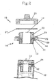
- FIG. 2 is the insert 13 from FIG. 1 shown in greater detail.
- the cover 33 is screwed onto the external thread of the pipe sleeve 30, wherein a sealing element 27 is provided for sealing the lid on the cover 24.
- an annular magnet 19 is used, which is held by means of locking screws 32 (shown schematically), which are screwed into provided for this purpose transverse openings 31 of the reducer.
- locking screws 32 shown schematically
- the magnet in the reducer can also be glued or held by collectable securing pins or the like.
- the shape of the magnet can vary.
- the opening 14 is dimensioned so that outlet pipes of diesel fuel nozzles do not fit through - outlet pipes of nozzles for urea but already.
- transverse openings 28 are further provided in this embodiment, in the locking screws 29 (shown schematically) are used for additional fixing of the insert member 13 in the filler neck.
- a related screw through the locking screws 29 in the openings 28 functions equally as anti-theft, because a mounted insert element can not be removed only by turning the reducer.
- the insert element is shown in the assembled state. As shown, the cover 24 is seated on the tank cap closure element 42 of the filler neck 10. In the lower Section of this illustration is shown in dashed line the position of a possibly pre-installed magnetic adapter. This makes it clear that the inventive insert element 13 for retrofitting in magnetic adapters containers may only have such dimensions that it projects only so deep into the filler neck that it does not encounter an existing magnetic adapter.
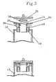
- FIG. 3 now shows a further embodiment of the insert element according to the invention, in which the reducer 16 has bayonet recesses 26, can engage in the lugs 36 of the lid 33 to form a bayonet closure between the lid and reducer.
- the reducer 16 has bayonet recesses 26
- the lugs 36 of the lid 33 can be engaged in the lugs 36 of the lid 33 to form a bayonet closure between the lid and reducer.
- a circle is shown open at two diametrically opposite sides.
- the lugs 36 are advantageously wedge-shaped, so that the seat of the lid becomes stronger with increasing rotation and this can not vibrate losvibrieren.
- This embodiment of the insert element can be seen in the assembled state.
- the lid protrudes only minimally from the cover 24 due to its low height.
- the minimum height of the lid 33 is based on the fact that no thread is provided in the lid, so that the actual lid surface of the lid 33 can be made narrow, or with low height.
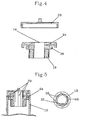
- FIG. 4 a further embodiment of the insert element is shown, in which the cover 24 over the outer edge of the closure element (in FIG. 4 not shown) of the filler neck 10 projects, and on the outer circumference Has thread which serves to screw with the internal thread of the cover 33.
- FIG. 5 shows an embodiment of the insert element, wherein the reducer is provided with arranged in the longitudinal direction of recesses 39. These recesses 39 serve to allow air to escape from the inner side of the tank even in the state of an inserted fuel nozzle.
- FIG. 5 For this purpose, a plan view with cut outlet pipe 12 of a fuel nozzle is shown. Here it can be clearly seen how 39 air can flow through the recesses 39 between the outer wall of the outlet pipe and the inner wall of the reducer.
- Reference numeral 22 denotes a level control tube of the fuel nozzle.
- FIG. 6 shows an embodiment with closure flap 44, which is made in two parts in this example. In the rest position, the filling opening is closed by the closure flap 44. In the upper part of Fig. 6 It is shown schematically what happens when trying with a diesel pistol to fill fuel into the AdBlue ⁇ tank: The fuel leaving the outlet pipe drains away without getting into the AdBlue ⁇ tank. This measure is advantageously improved by means of the drainage channels 45. Only by inserting the outlet pipe of an AdBlue ⁇ -Zapfpistole the shutter 44 is pivoted and AdBlue ⁇ urea can be filled.
Landscapes
- Engineering & Computer Science (AREA)
- Chemical & Material Sciences (AREA)
- Mechanical Engineering (AREA)
- Combustion & Propulsion (AREA)
- Chemical Kinetics & Catalysis (AREA)
- Transportation (AREA)
- Toxicology (AREA)
- General Engineering & Computer Science (AREA)
- Health & Medical Sciences (AREA)
- Life Sciences & Earth Sciences (AREA)
- Sustainable Development (AREA)
- Sustainable Energy (AREA)
- Cooling, Air Intake And Gas Exhaust, And Fuel Tank Arrangements In Propulsion Units (AREA)
- Exhaust Gas After Treatment (AREA)
- Closures For Containers (AREA)
Description
- Die Erfindung betrifft ein Einsatzelement für einen mit einer Einfüllöffnung versehenen Behälter, der zur tankstellenseitigen Befüllung mit Harnstoff mittels einer Zapfpistole geeignet ist. Die Erfindung betrifft auch einen Tankbehälter mit einem solchen Einsatzelement, durch das zu verhindern ist, dass versehentlich Kraftstoff in den Behälter eingefüllt wird.
- Im Stand der Technik werden die beim Betrieb von Verbrennungsmotoren entstehenden Stickoxide unter anderem durch selektive katalytische Reduktion reduziert, indem die Abgase der Brennkraftmaschine durch einen sog. SCR-Katalysator (Selectiv Catalytic Reduction) geleitet werden. Zur chemischen Umwandlung der Stickoxide wird der SCR-Katalysator mit einer hochreinen, wasserklaren Harnstofflösung betrieben. Diese nach DIN genormte Harnstofflösung wird unter der Marke "AdBlue"© geführt.
- Aufgrund der steigenden Nachfrage wird die AdBlue©-Harnstofflösung von immer mehr Tankstellenunternehmen an Zapfsäulen angeboten. Für die Verwendung von AdBlueⓒ ist am Fahrzeug ein zusätzlicher Tank vorgesehen, der auf gleiche Weise mit einer Zapfpistole einer Zapfsäule befüllt werden kann, wie das aus der Tankbefüllung mit Brennkraftstoff bekannt ist.
- Da nun an einer Tankstelle unterschiedliche Brennkraftstoffe und auch AdBlueⓒ-Harnstoff aus Zapfsäulen entnehmbar sind, besteht die Gefahr einer Verwechslung des jeweiligen Füllmediums. Diese Gefahr ist zwischen Harnstoff und Diesel am größten, da obige SCR-Katalysatoren vorrangig in großvolumigen Dieselmaschinen von beispielsweise Lastkraftwagen verbaut werden, weil ein Harnstoff-Behälter mitgeführt werden muss, der zusätzlichen Raumbedarf und Gewicht bedeutet.
- Um hier auszuschließen, dass AdBlue© in einen Kraftstofftank gefüllt wird, ist in der Zapfpistole für Harnstoff an ihrem Auslaufrohr innenrohrseitig ein automatisches Magnetventil vorgesehen, das im Ruhezustand die Auslauföffnung des Auslaufrohres verschließt. Damit ist eine AdBlue©-Abgabe selbst beim Betätigen der Zapfpistole bei geschlossenem Magnetventil unmöglich. Um nun einen Harnstoff-Fluss durch die Zapfpistole bewerkstelligen zu können, muss sich im Einfüllstutzen eines für AdBlue© bestimmten Behälters ein Magnetadapter befinden, der beim Vorbeiführen des Auslaufrohres einer Harnstoff-Zapfpistole das hierin angeordnete Magnetventil zu öffnen vermag. Bei geöffnetem Magnetventil kann der Harnstoff am Auslaufrohr der Zapfpistole dann austreten. Ein solcher Magnetadapter, der u.a. auch in einer Ausführung zur Nachrüstung bestehender AdBlue-Tanks speziell ausgebildet sein kann, ist in der
EP 1 502 794 B1 beschrieben. - Während, wie oben dargestellt, das Einfüllen von Harnstoff in den Dieseltank aufgrund des geschlossenen Magnetventils in der Zapfpistole unmöglich gemacht wird, wird das umgekehrte Befüllen des Harnstoffbehälters mit Diesel im Stand der Technik dadurch verhindert, indem die Einfüllöffnung so klein bemessen wird, dass eine Diesel-Zapfpistole mit ihrem Auslaufrohr nicht hindurch passt. Zu diesem Zweck werden für den AdBlue-Harnstoff ausschließlich Zapfpistolen verwendet, die gegenüber einer standardisierten Diesel-Zapfpistole ein Auslaufrohr mit kleinerem Durchmesser haben. Dieser besagte kleinere Durchmesser des Auslaufrohres entspricht bei Harnstoff-Zapfpistolen derzeit dem Durchmesser von Standard-Benzinzapfpistolen. Um zu verhindern, dass eine im Durchmesser des Auslaufrohres größere Dieselzapfpistole mit einem größeren Durchmesser in den Harnstoffbehälter versehentlich eingeführt werden könnte, weist der bereits im Einfüllstutzen des Harnstoffbehälters vorgesehene Magnetadapter eine Einfüllöffnung auf, deren Durchmesser kleiner ist als der Durchmesser des Diesel-Zapfpistolenauslaufrohres - wohingegen er so ausreichend groß ist, dass eine Zapfpistole mit 19 mm Auslaufrohr eingesteckt werden kann.
- Nachteilhaft an dieser im Stand der Technik verbreiteten Lösung ist jedoch die Positionierung des Magnetadapters zu tief im Einfüllstutzen des AdBlue©-Behälters, damit ein herkömmlicher Einfüllstutzen mit herkömmlichen Bajonett-Tankdeckeln verschließbar ist. Setzt man nun eine Dieselzapfpistole am Einfüllstutzen eines AdBlue©-Behälters an und führt das Zapfpistolen-Auslaufrohr bis zur Öffnung des Magnetadapters, so kann sich beim Drückern der Pistole ausreichend Dieselkraftstoff im Einfüllstutzen bis zur oberen Einfüllöffnung desselben sammeln, wobei dieser sich im Einfüllstutzen ansammelnde Dieselkraftstoff natürlich in den AdBlueⓒ-Behälter läuft.
- Aufgabe der Erfindung ist es daher, eine verbesserte Lösung einer Befüllsicherung für AdBlue©-Harnstoffbehälter vorzusehen, die u.a. auch eine Nachrüstung an bestehenden Behälter berücksichtigt.
- Gelöst wird diese Aufgabe durch die Bereitstellung eines Einsatzelements, das ein Abdeckelement mit einer Öffnung aufweist, deren lichte Weite kleiner ist als der Außendurchmesser eines für Dieselkraftstoff standardisierten Zapfpistolenauslaufrohres, sowie ein Haltemittel umfasst, mit dem das Abdeckelement an der Öffnungsebene des Einfüllstutzens positioniert befestigbar ist.
- Grundgedanke der Erfindung ist es damit, die Einfüllöffnung am Außenrand - gesehen entlang der Längsrichtung des Einfüllstutzens - mit einem Abdeckelement zu versehen, das verhindert, dass sich vor dem Abdeckelement Dieselkraftstoff sammeln kann, der dann in den AdBlue©-Behälter einfließen könnte. Da mit anderen Worten das Abdeckelement erfindungsgemäß an der Öffnungsebene des Einfüllstutzens angeordnet ist, kann sich im Einfüllstutzen selbst beim versehentlichen Betätigen einer Diesel-Zapfpistole, Dieselkraftstoff nicht vor dem Abdeckelement sammeln, da der Dieselkraftstoff sofort auf den Boden abtropft. In einem solchen Moment wird sofort bemerkt werden, dass ein Befüllen fehlschlägt, sodass der Tankvorgang abgebrochen wird, bevor auch nur minimale Mengen falschen Kraftstoffs in den AdBlue©-Tank gelangen.
- Im einfachsten Fall beinhaltet die Lösung ein Einsatzelement in Form einer über das Ende des Einfüllstutzens setzbaren Verschlusskappe, wobei das Abdeckelement mittels des Zylindermantels der Kappe als Haltemittel auf dem Ende des Einfüllstutzens an dessen Öffnungsebene gehalten wird. Das Abdeckelement hat dabei eine Öffnung, die das Einführen eines Auslaufrohres einer Harnstoff-Zapfpistole erlaubt, jedoch das Einführen einer Dieselzapfpistole verhindert.
- Damit ein derartiges Einsatzelement auch verschließbar ist, weist das Abdeckelement an der Tank abgewandten Seite eine Rohrmuffe mit Außengewinde auf, auf die ein Deckel des Einsatzelementes aufgeschraubt werden kann. Dabei ist zu beachten, dass der Innendurchmesser der Rohrmuffe bündig mit der Öffnung des Abdeckelements 24 abschließen muss. Dann bildet nämlich die Innenfläche der Rohrmuffe mit der Öffnung des Abdeckelements eine in Längsrichtung des Einsatzelementes durchgehende Zylinderwand. So ist auch bei dieser Ausführungsform gewährleistet, dass sich kein Füll-Medium zwischen Abdeckelement und Innenwand der Rohrmuffe sammeln kann.
- In vorteilhafter Weise ist es vorgesehen, dass entweder das Gewinde des Deckels oder das Gewinde der Rohrmuffe ein sog. ansteigendes Gewinde ist, um einen Widerstand zum Lösen des Deckels von der Rohrmuffe zu schaffen, so dass der Deckel nur durch gewollte manuelle Drehung lösbar ist. Alternativ ist eine Lösung vorgeschlagen, bei der am Umfang der Öffnung des Abdeckelements zwei gegenüberliegende Ausnehmung vorgesehen sind, in die an der Unterseite des Deckels vorgesehene Nasen eingreifen können, so dass zwischen Deckel und Reduzierstück ein Bajonettverschluss gebildet ist.
- Gemäß einer vorteilhaften Ausführungsform weist das erfindungsgemäße Einsatzelement ein in den Einfüllstutzen des Behälters einschiebbares Reduzierstück auf. In diesem Reduzierstück kann dann in vorteilhafter Weise ein Magnet aufgenommen sein, der mit einem in einer Harnstoff-Zapfpistole vorgesehenen Magnetschalter wechselwirken, d.h. diesen öffnen kann. Bei dieser Ausführungsform wird der im Stand der Technik im Einfüllstutzen tief sitzende Magnetadapter hinfällig. Diese Lösung mit im Reduzierstück integriertem Magnetadapter gewährleistet eine sicheres Schalten des Magnetventils der Zapfpistole, weil es sein kann, dass der bereits bestehende installierte Magnetadapter derart tief im Einfüllstutzen positioniert ist, dass dieser Magnetadapter beim Einschieben einer AdBlue©Zapfpistole das Magnetventil nicht mehr zu schalten vermag, weil die Zapfpistole nicht mehr so weit wie ursprünglich, d.h. ohne Einsatzelement eingeschoben werden kann. Dann muss zum Erwirken eines Harnstoff-Flusses der Magnet näher zum Abdeckelement hin platziert sein, was mit dieser Ausführungsform eines integrierten Magnetadapters im Reduzierstück geschaffen ist.
- Die Tiefe des Reduzierstückes, mit der das Einsatzelement in den Einfüllstutzen einragt, ist dabei so bemessen, dass ein bereits vorliegender Magnetadapter nicht kontaktiert wird. Dies ist insbesondere dann erforderlich, wenn ein Harnstoffbehälter, der bereits mit einem Magnetadapter versehen ist, mit dem erfindungsgemäßen Einsatzelement nachgerüstet werden soll.
- In einer vorteilhaften Ausführungsform weist das Reduzierstück am Außenumfang ein Außengewinde auf, mit dem das Reduzierstück in den Einfüllstutzen des Behälters einschraubbar ist.
- Gemäß einer alternativen Ausführungsform ist vorgesehen, dass das Reduzierstück am Außenumfang Nasen aufweist, die mit dem Tankdeckelverschlusssystem des Einfüllstutzens zusammen einen Bajonettverschluss bilden. Beim Montieren des Einsatzelements wird dabei das Abdeckelement auf den Außenrand des Einfüllstutzens gedrückt und schließt diesen dichtend ab. Hierzu ist es insbesondere von Vorteil zwischen Abdeckelement und Außenrand eine Dichtung vorzusehen, die von dem Abdeckelement getragen wird.
- Auch kann bei einer vorteilhaften Ausführungsform mit Reduzierstück dieses an seiner Einfüll-Öffnungsseite eine Bajonett-Ausnehmung haben. Das bedeutet, dass am Umfang der Öffnung des Abdeckelements zwei gegenüberliegende Ausnehmung vorgesehen sind, in die an der Unterseite des Deckels vorgesehene Nasen eingreifen können, so dass zwischen Deckel und Reduzierstück gleichermaßen ein Bajonettverschluss gebildet ist.
- Der Deckel kann mittels einer Seilhalterung oder dergleichen am Reduzierstück bzw. dem Abdeckelement gesichert sein, damit dieser nicht verloren geht.
- Da beim Einfüllen von Harnstoff in den Behälter die in letzterem vorliegende Luft entweichen muss und die Toleranzen zum Einpassen einer vorbestimmten Zapfpistole mit reduziertem Auslaufrohr gering sind, ist in vorteilhafter Weise vorgesehen, dass am Innenumfang des Reduzierstücks Ausnehmungen in seiner axialen Längsrichtung vorgesehen sind, so dass zwischen einer in das Einsatzelement eingesetzten Harnstoff-Zapfpistole und dem Reduzierstück Luft vom Innenraum des Behälters nach außen strömen kann. Die Größe der Ausnehmungen ist dabei abhängig vom Mengenfluss an AdBlue©-Harnstoff in den Tank - was der Fachmann zu bemessen weiß.
- Gemäß einer weiteren vorteilhaften Ausführungsform weist das Einsatzelement einen Spezialwerkzeugschlüssel auf, der Nasen hat, die in oben genannte Ausnehmungen bzw. in die Bajonettausnehmung des Abdeckelements greifen können, um das Einsatzelement auf einem Einfüllstutzen durch Verdrehen zu arretieren.
- Schließlich kann vorgesehen sein, dass eine Diebstahlsicherung des Einsatzelements in Form einer Schraube vorgesehen ist, die in eine in dem Reduzierstück quer zu seiner Achse vorgesehene Bohrung eindrehbar ist, so dass das Einsatzelement in dem Einfüllstutzen arretiert ist.
- Die Erfindung betrifft schlussendlich einen Behälter für Harnstoff als Kfz-Tank, dessen Einfüllstutzen mit einem Einsatzelement nach obiger Beschreibung ausgerüstet ist. Das Einsatzelement kann dabei mit dem Einfüllstutzen einteilig ausgeführt sein.
- Ferner betrifft die Erfindung einen mobilen, d.h. tragbaren Behälter mit einer Einfüllöffnung und einem die Einfüllöffnung verschließbaren, abnehmbaren Deckel, durch welche Einfüllöffnung mit Hilfe einer tankstellenseitigen Zapfpistole Harnstoff in den geöffneten Behälter gefüllt werden kann, wobei die Einfüllöffnung an ihrem in der Öffnungsebene liegenden Außenrand eine lichte Weite hat, die kleiner ist als der Außendurchmesser des für Dieselkraftstoff standardisierten Zapfpistolenauslaufrohres. Das bedeutet, dass das Auslaufrohr einer Zapfpistole mit zu großem Öffnungsdurchmesser keinen noch so minimalen Weg in den Behälter geführt werden kann.
- In vorteilhafte Weiterbildung weist der tragbare Kanister unterhalb des Abdeckelements ein Magnet auf.
- Als vorteilhaft ist für alle Ausführungsvarianten des Einsatzelements, des mobilen Kanisters oder Tanks angesehen, dass an der Einfüllöffnung eine Verschlussklappe angeordnet ist, die durch das Einschieben eines AdBlue-Auslaufrohres verschwenkt werden kann, um das Auslaufrohr tiefer in den Tank zu stecken. Diese Verschlussklappe schützt davor, dass auch mutwillig an die Öffnung des AdBlueⓒ-Tanks herangeführte Falsch-Flüssigkeiten nicht in den AdBlueⓒ-Tank gelangen. Gemäß einer Weiterführung dieser Ausführungsform ist ferner mindestens ein Kanal vorgesehen, der die Einfüllöffnung mit dem Rand des Einfüllstutzens verbindet, sodass eine auf die Verschlussklappe auftreffende Flüssigkeit über diesen Kanal nach außen ablaufen kann - also nicht in den AdBlue©-Tank gelangt. Die Verschlussklappe kann einteilig oder mehrteilig sein. Sie ist über ein Gelenk bewegbar gelagert, wobei sie vorteilhaft mit einer Feder vorgespannt ist, wodurch die Verschlussklappe in ihrer Ruhestellung in eine die Einfüllöffnung verschließende Position gebracht wird.
- Die Erfindung wird nun mit Bezug auf die beigefügten Zeichnungen näher erläutert. In diesen zeigt
- Fig.1
- das erfindungsgemäße Einsatzelement in perspektivischer Ansicht, wie es auf den Einfüllstutzen zu setzen ist;
- Fig. 2
- eine Ausführungsform des erfindungsgemäßen Einsatzelements in Explosionsansicht und in einer am Einfüllstutzen montierten Ansicht;
- Fig. 3
- eine weitere Ausführungsform des erfindungsgemäßen Einsatzelements;
- Fig. 4
- eine weitere alternative Ausführungsform des Einsatzelements;
- Fig. 5
- eine andere Ausführungsform des Einsatzelements; und
- Fig. 6
- eine Ausführungsform der Erfindung mit Verschlussklappe
-
Figur 1 zeigt das erfindungsgemäße Einsatzelement 13 in perspektivischer Ansicht, wie es auf einem Einfüllstutzen 10 eines Tankbehälters aufsetzbar ist. Das Abdeckelement 24 hat eine Einführ-Öffnung (in dieser perspektivischen Darstellung nicht zu sehen), die das Einführen eines Auslaufrohres einer Harnstoff-Zapfpistole erlaubt, jedoch das Einführen einer Dieselzapfpistole verhindert. Mit anderen Worten hat das Abdeckelement einen ÖffnungsDurchmesser, so dass Zapfpistolen 12 mit einem reduzierten Durchmesser in den Einfüllstutzen 10 eingeführt werden können, wohingegen Zapfpistolen mit einem vergrößerten Auslaufrohr nicht durch die Öffnung des Abdeckelementes passen. InFigur 1 sind im unteren Bildabschnitt zwei Zapfpistolen mit unterschiedlichem Auslaufrohr gezeigt. Die linke Zapfpistole mit einem Auslaufrohr von ca. 21 mm ist für die standardisierte AdBlue-Betankung vorgesehen, wohingegen die rechte Darstellung eine Diesel-Zapfpistole mit größerem Auslauf-Durchmesser aufzeigt. Mit der Bezugsziffer 27 sind jeweils die Füllstands-Röhrchen der Zapfpistole gekennzeichnet, die zum automatischen Abschalten der Zapfpistole bei vollem Tank Einsatz finden. - Der Einfüllstutzen 10 weist ein herkömmliches Tankdeckel-Verschlusselement 42 am Außenrand des Einfüllstutzens auf. Komplementär zu diesem Tankdeckel-Verschlusselement 42 mit seinen zwei gegenüberliegenden Ausnehmungen weist das Einsatzelement zwei Nasen 36 auf, so dass aus der Kombination des Verschlusselementes mit den Nasen und dem Abdeckelement 24 ein Bajonett-Verschluss gebildet ist. Beim Arretieren des Einsatzelementes wird das Abdeckelement 24 auf die Oberseite des Tankdeckel-Verschlusselementes gedrückt. Ein unterhalb des Abdeckelements angeordneter Dichtungsring (hier nicht gezeigt) schafft einen dichten Verschluss.
- Damit das Einsatzelement 13 selbst verschlossen werden kann, ist an der Oberseite des Abdeckelements 24 eine Rohrmuffe 30 mit Außengewinde angeordnet, auf das ein Deckel (in dieser Darstellung nicht gezeigt) des Einsatzelementes aufgeschraubt werden kann. Bei dieser Ausführungsform mit Rohrmuffe ist zu beachten, dass deren Innendurchmesser bündig mit der Öffnung des Abdeckelements 24 abschließen sollte. Mit anderen Worten bildet die Innenfläche der Rohrmuffe dann mit der Öffnung des Abdeckelements eine in Längsrichtung des Einsatzelementes durchgehende Zylinderwand. Dann ist auch bei dieser Ausführungsform gewährleistet, dass sich kein Medium zwischen Abdeckelement 24 und Innenwand der Rohrmuffe sammeln kann und eine herangeführte Zapfpistole mit ihrem Auslaufrohr nur bis an die Öffnungsebene der Rohrmuffe gelangt und nicht weiter hinein zum Abdeckelement (siehe hierzu Detail in
Fig. 2 ). - In
Figur 2 ist das Einsatzelement 13 ausFigur 1 in größerem Detail gezeigt. Der Deckel 33 ist am Außengewinde der Rohrmuffe 30 aufschraubbar, wobei ein Dichtelement 27 zum Abdichten des Deckels am Abdeckelement 24 vorgesehen ist. An der Unterseite des Einsatzelementes 13 ist ein ringförmiger Magnet 19 eingesetzt, der mittels Sicherungsschrauben 32 (schematisch dargestellt) gehalten wird, die in hierfür vorgesehene quer liegende Öffnungen 31 des Reduzierstücks eingeschraubt werden. Es ist dabei selbstverständlich, dass der Magnet in dem Reduzierstück auch verklebt bzw. durch einzutreibende Sicherungsstifte oder dergleichen gehalten werden kann. Auch kann die Form des Magneten variieren. Die Öffnung 14 ist so bemessen, dass Auslaufrohre von Diesel-Zapfpistolen nicht hindurch passen - Auslaufrohre von Zapfpistolen für Harnstoff aber schon. - In dem Reduzierstück 16 sind bei dieser Ausführungsform ferner quer liegende Öffnungen 28 vorgesehen, in die Sicherungsschrauben 29 (schematisch dargestellt) zum zusätzlichen Fixieren des Einsatzelementes 13 im Einfüllstutzen dienen. Eine diesbezügliche Verschraubung durch die Sicherungsschrauben 29 in den Öffnungen 28 fungiert gleichermaßen als Diebstahlsicherung, weil ein derart montiertes Einsatzelement nicht mehr nur durch Drehen des Reduzierstückes entnommen werden kann.
- In der unteren Darstellung von
Figur 2 ist das Einsatzelement im montierten Zustand dargestellt. Wie gezeigt sitzt das Abdeckelement 24 auf dem Tankdeckel-Verschlusselement 42 des Einfüllstutzens 10. Im unteren Abschnitt dieser Darstellung ist in gestrichelter Linie die Position eines gegebenenfalls bereits vorinstallierten Magnetadapters zu sehen. Hierdurch wird deutlich, dass das erfindungsgemäße Einsatzelement 13 zum Nachrüsten in mit Magnetadaptern bestehenden Behältern nur solche Abmessungen haben darf, dass es nur so tief in den Einfüllstutzen einragt, dass es nicht auf einen bestehenden Magnetadapter stößt. -
Figur 3 zeigt nun eine weitere Ausführungsform des erfindungsgemäßen Einsatzelementes, bei dem das Reduzierstück 16 Bajonett-Ausnehmungen 26 aufweist, in die Nasen 36 des Deckels 33 zur Bildung eines Bajonett-Verschlusses zwischen Deckel und Reduzierstück greifen können. In der Draufsicht auf das Reduzierstück, d.h. auf dessen Öffnungsseite zeigt sich ein an zwei diametral gegenüberliegenden Seiten offener Kreis. Die Nasen 36 sind vorteilhaft keilförmig ausgebildet, sodass der Sitz des Deckels mit zunehmender Drehung fester wird und dieser nicht losvibrieren kann. In der unteren Darstellung vonFigur 3 ist diese Ausführungsform des Einsatzelementes im montierten Zustand zu sehen. - Bei dieser Ausführungsform ist ferner vorteilhaft realisiert, dass der Deckel aufgrund seiner geringen Höhe nur minimal vom Abdeckelement 24 abragt. Die minimale Höhe des Deckels 33 geht dabei darauf zurück, dass im Deckel kein Gewinde vorzusehen ist, so dass die eigentliche Deckelfläche des Deckels 33 schmal, bzw. mit geringer Höhe ausgeführt werden kann.
- In
Figur 4 ist eine weitere Ausführungsform des Einsatzelementes gezeigt, bei der das Abdeckelement 24 über den Außenrand des Verschlusselementes (inFigur 4 nicht gezeigt) des Einfüllstutzens 10 ragt, und am Außenumfang ein Gewinde aufweist, das zum Verschrauben mit dem Innengewinde des Deckel 33 dient. -
Figur 5 zeigt eine Ausführungsform des Einsatzelementes, bei dem das Reduzierstück mit in dessen Längsrichtung angeordneten Ausnehmungen 39 versehen ist. Diese Ausnehmungen 39 dienen dazu, dass Luft von der Tankinnenseite selbst im Zustand einer eingeschobenen Zapfpistole austreten kann. In der rechtsseitigen Darstellung vonFigur 5 ist hierzu eine Draufsicht mit geschnittenem Auslaufrohr 12 einer Zapfpistole gezeigt. Hier ist deutlich zu erkennen, wie zwischen der Außenwand des Auslaufrohres und der Innenwand des Reduzierstücks 16 mittels den Ausnehmungen 39 Luft hindurchströmen kann. Mit Bezugsziffer 22 ist ein Füllstandregel-Röhrchen der Zapfpistole bezeichnet. -
Figur 6 zeigt eine Ausführungsform mit Verschlussklappe 44, die in diesem Beispiel zweiteilig ausgeführt ist. In der Ruhestellung wird durch die Verschlussklappe 44 die Einfüllöffnung verschlossen. In der oberen Darstellung vonFig. 6 ist schematisch gezeigt, was passiert, wenn mit einer Dieselpistole versucht wird, Kraftstoff in den AdBlue©-Tank einzufüllen: Der aus dem Auslaufrohr austretende Kraftstoff fließt ab, ohne in den AdBlue©-Tank zu gelangen. Diese Maßnahme wird vorteilhaft mit Hilfe der Ablaufkanäle 45 verbessert. Erst durch Einschieben des Auslaufrohres einer AdBlue©-Zapfpistole wird die Verschlussklappe 44 verschwenkt und AdBlue©-Harnstoff kann eingefüllt werden.Bezugszeichenliste 10 Einfüllstutzen eines Behälters 12 Zapfpistole, bzw. deren Auslaufrohr 13 Einsatzelement 14 Öffnung des Einsatzelementes 16 Reduzierstück 19 Magnet 22 Füllstandregler-Röhrchen 24 Abdeckelement 26 Bajonett-Ausnehmung 27 Dichtung 28 Öffnung für Sicherung am Einfüllstutzen 29 Sicherungsschraube 30 Rohrmuffe mit Außengewinde 31 Öffnung für Sicherung des Magneten 32 Sicherungsschraube 33 Deckel 36 Nasen für Bajonett-Verschluss 39 Ausnehmungen 42 Tankdeckel-Verschlusselement 44 Verschlussklappe 45 Ablaufkanal
Claims (18)
- Einsatzelement (13) für einen mit einem Einfüllstutzen (10) versehenen Behälter, der zur tankstellenseitigen Befüllung mit Harnstoff mittels einer Zapfpistole (12) geeignet ist, welches Einsatzelement (13)- ein Abdeckelement (24) mit einer Öffnung, deren lichte Weite kleiner ist als der Außendurchmesser eines für Dieselkraftstoff standardisierten Zapfpistolen-Auslaufrohres (12),- sowie ein Haltemittel aufweist, mit dem das Abdeckelement (24) an der Öffnungsebene des Einfüllstutzens (10) positioniert befestigbar ist, sodass sich Diesel-Kraftstoff nicht vor dem Abdeckelement sammeln kann.
- Einsatzelement (13) gemäß Anspruch 1,
dadurch gekennzeichnet, dass das Einsatzelement ein in den Einfüllstutzen (10) des Behälters einschiebbares Reduzierstück (16) aufweist. - Einsatzelement (13) gemäß Anspruch 1 oder 2,
dadurch gekennzeichnet, dass in dem Reduzierstück (16) ein Magnet (19) aufgenommen ist, der mit einem in Harnstoff-Zapfpistolen (12) vorgesehenen Magnetschalter wechselwirken kann. - Einsatzelement (13) gemäß einem der vorangehenden Ansprüche 2 oder 3,
dadurch gekennzeichnet, dass das Reduzierstück (16) am Außenumfang ein Außengewinde aufweist, mit dem das Reduzierstück in den Einfüllstutzen (10) des Behälters eingeschraubt werden kann. - Einsatzelement (13) gemäß einem der vorangehenden Ansprüche 2 bis 3,
dadurch gekennzeichnet, dass das Reduzierstück (16) am Außenumfang Nasen (36) aufweist, die mit einem Tankdeckel-Verschlusselement (42) des Einfüllstutzens (10) zusammen einen Bajonett-Verschluss bilden. - Einsatzelement (13) nach einem der Ansprüche 1 bis 5,
dadurch gekennzeichnet, dass das Abdeckelement (24) an seiner Einfüllöffnungsseite eine Rohrmuffe mit Außengewinde (30) aufweist, und das Einsatzelement ferner einen Deckel (33) mit Innengewinde umfasst, der zum Verschließen des Einsatzelements (13) auf die Rohrmuffe aufschraubbar ist. - Einsatzelement (13) nach Anspruch 6,
dadurch gekennzeichnet, dass das Gewinde des Deckels (33) oder das für das Deckelgewinde komplementäre Gewinde der Rohrmuffe (30) ein ansteigendes Gewinde ist, um einen Widerstand zum Lösen des Deckels von der Rohrmuffe zu schaffen, sodass der Deckel nur durch gewollte manuelle Drehung lösbar ist. - Einsatzelement (13) nach einem der Ansprüche 2 bis 7,
dadurch gekennzeichnet, dass das Reduzierstück (16) an seiner Einfüllöffnungsseite eine Bajonett-Ausnehmung hat, und ein Deckel für das Einsatzelement (13) vorgesehen ist, der an seiner Unterseite Nasen aufweist, die zur Bildung eines Bajonett-Verschlusses zwischen Deckel und Reduzierstück in die Bajonett-Ausnehmung greifen. - Einsatzelement (13) nach einem der Ansprüche 2 bis 8,
dadurch gekennzeichnet, dass am Innenumfang des Reduzierstücks (16) Ausnehmungen (39) in seiner axialen Längsrichtung vorgesehen sind, sodass zwischen einer in das Einsatzelement eingesetzten Harnstoff-Zapfpistole (12) und dem Reduzierstück (16) Luft hindurchströmen kann. - Einsatzelement (13) nach Anspruch 8 oder 9,
dadurch gekennzeichnet, dass das Einsatzelement einen Spezial-Werkzeugschlüssel umfasst, der mit Nasen in die Ausnehmungen (39) oder die BajonettAusnehmung greifen kann, um das Einsatzelement (13) in einem Einfüllstutzen durch Verdrehen desselben zu arretieren. - Einsatzelement (13) nach einem der Ansprüche 2 bis 10,
dadurch gekennzeichnet, dass eine Diebstahlsicherung des Einsatzelements (13) in Form einer Schraube vorgesehen ist, die in eine in dem Reduzierstück (16) quer zu seiner Achse vorgesehenen Bohrung eindrehbar ist, sodass das Einsatzelement (13) in dem Einfüllstutzen (10) arretiert werden kann. - Einsatzelement nach einem der vorangehenden Ansprüche,
dadurch gekennzeichnet, dass das Abdeckelement (24) eine deren Öffnung überdeckende verschwenkbare Verschlussklappe (44) aufweist. - Einsatzelement nach Anspruch 12,
dadurch gekennzeichnet, dass mindestens ein Ablaufkanal (45) vorgesehen ist, über den bei geschlossener Verschlussklappe (44) auf diese auftreffende Flüssigkeit abgeleitet wird. - KFZ-Behälter für Harnstoff, dessen Einfüllstutzen mit einem Einsatzelement (13) gemäß einem der Ansprüche 1 bis 13 ausgerüstet ist.
- Mobiler Behälter mit einer Einfüllöffnung und einem die Einfüllöffnung verschließbaren, abnehmbaren Deckel, durch welche Einfüllöffnung mit Hilfe einer tankstellenseitigen Zapfpistole (12) Harnstoff in den geöffneten Behälter gefüllt werden kann,
dadurch gekennzeichnet, dass die Einfüllöffnung an ihrem Außenrand eine lichte Weite hat, die kleiner ist als der Außendurchmesser des für Dieselkraftstoff standardisierten Zapfpistolen-Auslaufrohres. - Mobiler Behälter nach Anspruch 15,
dadurch gekennzeichnet, dass in der Einfüllöffnung unterhalb ihres Außenrandes ein Magnet angeordnet ist, der mit einem in Zapfpistolen vorgesehenen Magnetschalter wechselwirken kann. - Mobiler Behälter nach Anspruch 15 oder 16,
dadurch gekennzeichnet, dass das Abdeckelement (24) eine deren Öffnung überdeckende verschwenkbare Verschlussklappe (44) aufweist. - Mobiler Behälter nach Anspruch 17,
dadurch gekennzeichnet, dass mindestens ein Ablaufkanal (45) vorgesehen ist, über den bei geschlossener Verschlussklappe (449 auf diese auftreffende Flüssigkeit abgeleitet wird.
Applications Claiming Priority (3)
| Application Number | Priority Date | Filing Date | Title |
|---|---|---|---|
| DE102008027463 | 2008-06-09 | ||
| DE102008049150A DE102008049150A1 (de) | 2008-06-09 | 2008-09-26 | Einsatzelement für einen zur tankstellenseitigen Befüllung mit Harnstoff geeigneten Behälter |
| PCT/EP2009/057084 WO2009150149A2 (de) | 2008-06-09 | 2009-06-09 | Einsatzelement für einen zur tankstellenseitigen befüllung mit harnstoff geeigneten behälter |
Publications (2)
| Publication Number | Publication Date |
|---|---|
| EP2300256A2 EP2300256A2 (de) | 2011-03-30 |
| EP2300256B1 true EP2300256B1 (de) | 2013-07-17 |
Family
ID=41268927
Family Applications (1)
| Application Number | Title | Priority Date | Filing Date |
|---|---|---|---|
| EP09761712.0A Not-in-force EP2300256B1 (de) | 2008-06-09 | 2009-06-09 | Einsatzelement für einen zur tankstellenseitigen befüllung mit harnstoff geeigneten behälter |
Country Status (5)
| Country | Link |
|---|---|
| US (1) | US8800611B2 (de) |
| EP (1) | EP2300256B1 (de) |
| DE (1) | DE102008049150A1 (de) |
| ES (1) | ES2431357T3 (de) |
| WO (1) | WO2009150149A2 (de) |
Families Citing this family (41)
| Publication number | Priority date | Publication date | Assignee | Title |
|---|---|---|---|---|
| DE102009009998A1 (de) * | 2009-02-23 | 2010-08-26 | Kt Projektentwicklungs Gmbh | Sicherheitselement für einen Diesel-Kraftstoffbehälter zur Unterbindung einer Fehlbetankung |
| DE102009029362A1 (de) | 2009-09-11 | 2011-03-24 | Erhard & Söhne GmbH | Behaelter zur Aufnahme eines Kraft- und/oder Betriebsstoffes fuer Fahrzeuge |
| EP2316685A1 (de) | 2009-10-21 | 2011-05-04 | Inergy Automotive Systems Research (Société Anonyme) | Verbessertes Füllsystem für Fahrzeugflüssigkeitsbehälter |
| US20160368758A1 (en) * | 2009-11-20 | 2016-12-22 | Jack R. BRAMMELL | Systems and Methods for On-Site Mixing and Dispensing of a Reducing Agent Solution for Use with a Diesel Catalytic Converter |
| DE202010001147U1 (de) * | 2009-12-22 | 2011-05-12 | Reutter Gmbh | Einfüllstutzen für einen Flüssigkeitstank, insbesondere Harnstofftank an Kraftfahrzeugen |
| DE202010016319U1 (de) * | 2010-12-04 | 2012-03-19 | Reutter Gmbh | Einsatz für einen Einfüllstutzen eines Harnstoffbehälters |
| DE102011009745B4 (de) | 2011-01-28 | 2012-09-13 | Kautex Textron Gmbh & Co. Kg | Einfüllstutzen für einen Nebenflüssigkeitsbehälter |
| DE202011100846U1 (de) * | 2011-05-16 | 2012-08-17 | Reutter Gmbh | Einfüllstutzen für einen Harnstoffbehälter und einen damit versehenen Harnstoffbehälter |
| DE102011113101A1 (de) | 2011-09-09 | 2013-03-14 | Volkswagen Aktiengesellschaft | Einfüllstutzen für ein Fahrzeug |
| DE102011115144A1 (de) * | 2011-09-27 | 2013-03-28 | Veritas Ag | Einfüllvorrichtung |
| US10000117B2 (en) | 2012-02-17 | 2018-06-19 | Stant Usa Corp. | Filler neck closure assembly |
| DE102012008418B4 (de) * | 2012-04-27 | 2020-03-05 | GM Global Technology Operations, LLC (n.d. Ges. d. Staates Delaware) | Adapter für einen Öleinfüllstutzen und Montageverfahren des Adapters |
| PL2687479T3 (pl) * | 2012-07-20 | 2016-07-29 | Elaflex Hiby Tanktechnik Gmbh & Co | Zawór dozujący |
| US9610836B2 (en) * | 2012-09-05 | 2017-04-04 | Ford Global Technologies, Llc | Venting system for a diesel exhaust fluid filler pipe |
| US9102229B2 (en) * | 2013-07-24 | 2015-08-11 | GM Global Technology Operations LLC | Oil filler neck for a cylinder head cover |
| DE102014100805B4 (de) * | 2014-01-24 | 2018-04-26 | Reutter Gmbh | Einrichtung zum Verhindern einer Fehlbefüllung eines Behälters |
| FR3017375B1 (fr) * | 2014-02-13 | 2016-02-12 | Peugeot Citroen Automobiles Sa | Reservoir de reducteur d'oxyde d'azote a mise en place d'aimant facilitee |
| US9624088B2 (en) | 2014-02-18 | 2017-04-18 | Husky Corporation | Safety interlock nozzle |
| USD739442S1 (en) * | 2014-03-21 | 2015-09-22 | Husky Corporation | Nozzle splash guard design |
| JP2016017409A (ja) * | 2014-07-04 | 2016-02-01 | キャタピラー エス エー アール エル | 尿素水タンク |
| CN104454094B (zh) * | 2014-11-17 | 2017-06-06 | 可附特汽车零部件制造(北京)有限公司 | 一种尿素管及其安装方法 |
| US9701531B2 (en) * | 2015-04-10 | 2017-07-11 | Veritas Ag | Filling head for a liquid tank |
| USD803049S1 (en) * | 2016-08-24 | 2017-11-21 | Lisle Corporation | Adapter for connecting a funnel to filling port of a vehicle crankcase |
| USD803048S1 (en) * | 2016-08-24 | 2017-11-21 | Lisle Corporation | Adapter for connecting a funnel to filling port of a vehicle crankcase |
| USD803047S1 (en) * | 2016-08-24 | 2017-11-21 | Lisle Corporation | Adapter for connecting a funnel to filling port of a vehicle crankcase |
| US10450180B2 (en) | 2016-08-24 | 2019-10-22 | Lisle Corporation | Multi-application oil funnel construction for refilling crankcases through a filling port |
| USD803045S1 (en) * | 2016-08-24 | 2017-11-21 | Lisle Corporation | Adapter for connecting a funnel to filling port of a vehicle crankcase |
| USD804945S1 (en) * | 2016-08-24 | 2017-12-12 | Lisle Corporation | Adapter for connecting a funnel to filling port of a vehicle crankcase |
| USD803046S1 (en) * | 2016-08-24 | 2017-11-21 | Lisle Corporation | Adapter for connecting a funnel to filling port of a vehicle crankcase |
| USD803050S1 (en) * | 2016-08-24 | 2017-11-21 | Lisle Corporation | Adapter for connecting a funnel to filling port of a vehicle crankcase |
| US10245529B2 (en) * | 2017-02-27 | 2019-04-02 | GM Global Technology Operations LLC | System and apparatus to improve venting and spill mitigation for tank |
| USD828752S1 (en) * | 2017-03-02 | 2018-09-18 | Lisle Corporation | Adapter for connecting a funnel to filling port of a vehicle crankcase |
| USD828751S1 (en) * | 2017-03-02 | 2018-09-18 | Lisle Corporation | Adapter for connecting a funnel to filling port of a vehicle crankcase |
| PT3369700T (pt) * | 2017-03-03 | 2021-08-06 | Elaflex Hiby Gmbh & Co Kg | Bocal de abastecimento para dois fluxos volumétricos máximos |
| KR102251333B1 (ko) * | 2017-05-18 | 2021-05-12 | 현대자동차주식회사 | 2 중 구조의 다중 경로 개폐 캡 장치 |
| US10640358B2 (en) | 2017-06-21 | 2020-05-05 | Ford Global Technologies, Llc | Capless refill adapter for a fluid refilling system |
| USD861053S1 (en) | 2017-11-17 | 2019-09-24 | Lisle Corporation | Adapter for connecting a funnel to filling port of a vehicle crankcase |
| KR102727901B1 (ko) * | 2019-04-29 | 2024-11-07 | 현대자동차주식회사 | 차량용 요소수주입구 개폐 장치 |
| CA3216738A1 (en) * | 2021-05-05 | 2022-11-10 | Brandon TRUAN | Automatic def tank filling system |
| CN114148162A (zh) * | 2021-12-20 | 2022-03-08 | 深圳清华大学研究院 | 一种自主加油系统的安全机械接口 |
| US12085216B2 (en) | 2022-02-17 | 2024-09-10 | Arctic Cat Inc. | Multi-use fuel filler tube |
Family Cites Families (22)
| Publication number | Priority date | Publication date | Assignee | Title |
|---|---|---|---|---|
| US3730216A (en) * | 1972-04-06 | 1973-05-01 | Ford Motor Co | Fuel tank insert for admitting preselected pump nozzles |
| DE3534361A1 (de) * | 1985-08-30 | 1987-03-26 | Schulte H J S Gmbh & Co | Verschluss fuer einen benzineinfuellstutzen eines kraftfahrzeuges |
| DE3530964C1 (en) * | 1985-08-30 | 1987-03-05 | Schulte H J S Gmbh & Co | Closure for a petrol filler neck of a motor vehicle |
| DE9204749U1 (de) * | 1992-04-06 | 1992-08-20 | Mecrom Ott u. Holey oHG, 8221 Hufschlag | Selbstschließender Tankverschluß |
| US6416943B1 (en) | 2000-11-14 | 2002-07-09 | Eastman Kodak Company | Color photographic element containing coupler useful for forming neutral silver-based image |
| US6390147B1 (en) * | 2001-05-17 | 2002-05-21 | Ford Global Technologies, Inc. | Fuel and reductant delivery system |
| DE20315807U1 (de) * | 2003-10-10 | 2003-12-11 | Jost, Ingo | Fehlbetankungseinsatz-Halterung für Fluidtanks an Kraftfahrzeugen |
| EP1502794B1 (de) * | 2003-08-01 | 2008-11-12 | Jost Automotive GmbH | Vorrichtung zum Vermeiden einer Fehlbetankung bei Kraftfahrzeugen |
| FR2868738B1 (fr) * | 2004-04-08 | 2006-07-14 | Itw De France Soc Par Actions | Embout pour tubulure de remplissage en carburant d'un vehicule |
| AT7933U1 (de) * | 2004-07-16 | 2005-11-15 | Tesma Motoren Getriebetechnik | Füllrohr für den treibstofftank eines kraftfahrzeuges mit selektiver öffnung |
| US7182111B2 (en) * | 2004-08-11 | 2007-02-27 | Stant Manufacturing Inc. | Fuel-dispensing nozzle inhibitor |
| DE202004013627U1 (de) * | 2004-09-01 | 2006-01-05 | DURA Automotive Systems Köhler GmbH | Einfüllstutzen für einen Kraftfahrzeug-Kraftstofftank |
| US7302977B2 (en) * | 2004-09-30 | 2007-12-04 | Stant Manufacturing Inc. | Fuel-dispensing nozzle inhibitor |
| US7665493B2 (en) * | 2005-02-10 | 2010-02-23 | Stant Manufacturing Inc. | Fuel-dispensing nozzle inhibitor |
| DE202005011575U1 (de) * | 2005-07-13 | 2006-11-23 | Reutter Metallwarenfabrik Gmbh | Einfüllstutzen für einen Behälter |
| DE202005012256U1 (de) * | 2005-07-27 | 2006-12-14 | Reutter Metallwarenfabrik Gmbh | Fehlbetankungsvorrichtung |
| US20080041492A1 (en) * | 2006-08-21 | 2008-02-21 | Martinrea Industries, Inc. | Automotive fuel filling system |
| US7644740B2 (en) * | 2007-03-01 | 2010-01-12 | Eaton Corporation | Fuel discriminating filler neck cover |
| AT9945U1 (de) * | 2007-03-27 | 2008-06-15 | Magna Steyr Fuel Systems Gesmb | Einfüllstutzen eines treibstofftanks mit schutz vor fehlbetankung |
| JP4778943B2 (ja) * | 2007-10-12 | 2011-09-21 | 本田技研工業株式会社 | 車両の給油口装置 |
| EP2093090B1 (de) * | 2008-02-21 | 2014-07-23 | Stant USA Corp. | Hemmvorrichtung für Kraftstoff-Zapfpistole |
| DE102009009998A1 (de) * | 2009-02-23 | 2010-08-26 | Kt Projektentwicklungs Gmbh | Sicherheitselement für einen Diesel-Kraftstoffbehälter zur Unterbindung einer Fehlbetankung |
-
2008
- 2008-09-26 DE DE102008049150A patent/DE102008049150A1/de not_active Withdrawn
-
2009
- 2009-06-09 EP EP09761712.0A patent/EP2300256B1/de not_active Not-in-force
- 2009-06-09 WO PCT/EP2009/057084 patent/WO2009150149A2/de not_active Ceased
- 2009-06-09 ES ES09761712T patent/ES2431357T3/es active Active
- 2009-06-09 US US12/996,762 patent/US8800611B2/en not_active Expired - Fee Related
Also Published As
| Publication number | Publication date |
|---|---|
| WO2009150149A2 (de) | 2009-12-17 |
| US8800611B2 (en) | 2014-08-12 |
| US20110100985A1 (en) | 2011-05-05 |
| ES2431357T3 (es) | 2013-11-26 |
| WO2009150149A3 (de) | 2010-07-22 |
| DE102008049150A1 (de) | 2009-12-10 |
| EP2300256A2 (de) | 2011-03-30 |
Similar Documents
| Publication | Publication Date | Title |
|---|---|---|
| EP2300256B1 (de) | Einsatzelement für einen zur tankstellenseitigen befüllung mit harnstoff geeigneten behälter | |
| EP2398664B1 (de) | Sicherheitselement für einen diesel-kraftstoffbehälter zur unterbindung einer fehlbetankung | |
| EP2276644B1 (de) | Stutzenabschluss für einen einfüllstutzen | |
| DE4233038C1 (de) | Überdrucksicherung für einen Kühlmittelkreislauf | |
| DE2362422A1 (de) | Selbsttaetig absperrende zapfpistole | |
| DE202010011973U1 (de) | Ölablassvorrichtung | |
| EP2666656A1 (de) | Einfüllstutzen eines Tanks eines Kraftfahrzeugs | |
| DE3121621C2 (de) | "Entlüftungseinrichtung für Kraftstofftanks von Fahrzeugen, insbesondere von Kraftfahrzeugen" | |
| DE19836104A1 (de) | Füllrohr für einen Kraftstofftank | |
| DE102011120787A1 (de) | Fehlbetankungsschutzvorrichtung für einen Einfüllstutzen eines Kraftstoffbehälters | |
| DE112005003208B4 (de) | Deckelloser Einfüllstutzen für den Tank eines Kraftfahrzeuges | |
| DE112006000847T5 (de) | Deckellose Verschlussanordnung für einen Kraftstofftankeinfüllstutzen und Verfahren zum deckellosen Verschließen desselben | |
| DE102008039150A1 (de) | Sicherheitselement für einen Diesel-Kraftstoffbehälter zur Unterbindung einer Fehlbetankung | |
| DE102008027462A1 (de) | Einsatzelement für einen Kraftstoffbehälter, der für eine Befüllung mit Dieselkraftstoff bestimmt ist | |
| EP0102083B1 (de) | Selbstschliessender Kraftstoffbehälterverschluss | |
| EP1986760B1 (de) | Filterpatrone zum einsetzen in einen wasservorratstank | |
| DE10110189B4 (de) | Kraftstoffbehälter | |
| DE8816045U1 (de) | Kraftstoff-Einfüllstutzen mit Absperrorgan | |
| DE102005053815A1 (de) | Entlüftungseinheit für das System zum Be- und Entlüften eines Kraftstoffbehälters | |
| EP1154909B1 (de) | Ventil und ein mit einem ventil versehener kraftstoffbehälter eines kraftfahrzeuges | |
| DE102018208468A1 (de) | Verschlussstopfen, Fluidbehälter und Fluidbehälterbaugruppe | |
| EP2179932B1 (de) | Verschlusseinrichtung zum Verschließen eines Behälters | |
| EP3771586B1 (de) | Einfüllstutzen | |
| DE19850382A1 (de) | Vorrichtung zum Ablaß des in einem Bauteil eines Kraftfahrzeuges enthaltenen Öls | |
| DE2950598C2 (de) | Kraftstofftank für Fahrzeuge, insbesondere für Kraftfahrzeuge |
Legal Events
| Date | Code | Title | Description |
|---|---|---|---|
| PUAI | Public reference made under article 153(3) epc to a published international application that has entered the european phase |
Free format text: ORIGINAL CODE: 0009012 |
|
| 17P | Request for examination filed |
Effective date: 20110107 |
|
| AK | Designated contracting states |
Kind code of ref document: A2 Designated state(s): AT BE BG CH CY CZ DE DK EE ES FI FR GB GR HR HU IE IS IT LI LT LU LV MC MK MT NL NO PL PT RO SE SI SK TR |
|
| AX | Request for extension of the european patent |
Extension state: AL BA RS |
|
| DAX | Request for extension of the european patent (deleted) | ||
| RAP1 | Party data changed (applicant data changed or rights of an application transferred) |
Owner name: TECINNOVATION GMBH |
|
| GRAP | Despatch of communication of intention to grant a patent |
Free format text: ORIGINAL CODE: EPIDOSNIGR1 |
|
| GRAS | Grant fee paid |
Free format text: ORIGINAL CODE: EPIDOSNIGR3 |
|
| GRAP | Despatch of communication of intention to grant a patent |
Free format text: ORIGINAL CODE: EPIDOSNIGR1 |
|
| INTG | Intention to grant announced |
Effective date: 20130426 |
|
| GRAA | (expected) grant |
Free format text: ORIGINAL CODE: 0009210 |
|
| AK | Designated contracting states |
Kind code of ref document: B1 Designated state(s): AT BE BG CH CY CZ DE DK EE ES FI FR GB GR HR HU IE IS IT LI LT LU LV MC MK MT NL NO PL PT RO SE SI SK TR |
|
| REG | Reference to a national code |
Ref country code: GB Ref legal event code: FG4D Free format text: NOT ENGLISH |
|
| REG | Reference to a national code |
Ref country code: CH Ref legal event code: EP |
|
| REG | Reference to a national code |
Ref country code: IE Ref legal event code: FG4D Free format text: LANGUAGE OF EP DOCUMENT: GERMAN |
|
| REG | Reference to a national code |
Ref country code: AT Ref legal event code: REF Ref document number: 621964 Country of ref document: AT Kind code of ref document: T Effective date: 20130815 |
|
| REG | Reference to a national code |
Ref country code: DE Ref legal event code: R096 Ref document number: 502009007613 Country of ref document: DE Effective date: 20130912 |
|
| REG | Reference to a national code |
Ref country code: ES Ref legal event code: FG2A Ref document number: 2431357 Country of ref document: ES Kind code of ref document: T3 Effective date: 20131126 |
|
| REG | Reference to a national code |
Ref country code: NL Ref legal event code: VDEP Effective date: 20130717 |
|
| REG | Reference to a national code |
Ref country code: LT Ref legal event code: MG4D |
|
| PG25 | Lapsed in a contracting state [announced via postgrant information from national office to epo] |
Ref country code: CY Free format text: LAPSE BECAUSE OF FAILURE TO SUBMIT A TRANSLATION OF THE DESCRIPTION OR TO PAY THE FEE WITHIN THE PRESCRIBED TIME-LIMIT Effective date: 20130710 Ref country code: HR Free format text: LAPSE BECAUSE OF FAILURE TO SUBMIT A TRANSLATION OF THE DESCRIPTION OR TO PAY THE FEE WITHIN THE PRESCRIBED TIME-LIMIT Effective date: 20130717 Ref country code: PT Free format text: LAPSE BECAUSE OF FAILURE TO SUBMIT A TRANSLATION OF THE DESCRIPTION OR TO PAY THE FEE WITHIN THE PRESCRIBED TIME-LIMIT Effective date: 20131118 Ref country code: SE Free format text: LAPSE BECAUSE OF FAILURE TO SUBMIT A TRANSLATION OF THE DESCRIPTION OR TO PAY THE FEE WITHIN THE PRESCRIBED TIME-LIMIT Effective date: 20130717 Ref country code: NO Free format text: LAPSE BECAUSE OF FAILURE TO SUBMIT A TRANSLATION OF THE DESCRIPTION OR TO PAY THE FEE WITHIN THE PRESCRIBED TIME-LIMIT Effective date: 20131017 Ref country code: IS Free format text: LAPSE BECAUSE OF FAILURE TO SUBMIT A TRANSLATION OF THE DESCRIPTION OR TO PAY THE FEE WITHIN THE PRESCRIBED TIME-LIMIT Effective date: 20131117 Ref country code: LT Free format text: LAPSE BECAUSE OF FAILURE TO SUBMIT A TRANSLATION OF THE DESCRIPTION OR TO PAY THE FEE WITHIN THE PRESCRIBED TIME-LIMIT Effective date: 20130717 |
|
| PG25 | Lapsed in a contracting state [announced via postgrant information from national office to epo] |
Ref country code: NL Free format text: LAPSE BECAUSE OF FAILURE TO SUBMIT A TRANSLATION OF THE DESCRIPTION OR TO PAY THE FEE WITHIN THE PRESCRIBED TIME-LIMIT Effective date: 20130717 Ref country code: LV Free format text: LAPSE BECAUSE OF FAILURE TO SUBMIT A TRANSLATION OF THE DESCRIPTION OR TO PAY THE FEE WITHIN THE PRESCRIBED TIME-LIMIT Effective date: 20130717 Ref country code: PL Free format text: LAPSE BECAUSE OF FAILURE TO SUBMIT A TRANSLATION OF THE DESCRIPTION OR TO PAY THE FEE WITHIN THE PRESCRIBED TIME-LIMIT Effective date: 20130717 Ref country code: GR Free format text: LAPSE BECAUSE OF FAILURE TO SUBMIT A TRANSLATION OF THE DESCRIPTION OR TO PAY THE FEE WITHIN THE PRESCRIBED TIME-LIMIT Effective date: 20131018 Ref country code: SI Free format text: LAPSE BECAUSE OF FAILURE TO SUBMIT A TRANSLATION OF THE DESCRIPTION OR TO PAY THE FEE WITHIN THE PRESCRIBED TIME-LIMIT Effective date: 20130717 Ref country code: FI Free format text: LAPSE BECAUSE OF FAILURE TO SUBMIT A TRANSLATION OF THE DESCRIPTION OR TO PAY THE FEE WITHIN THE PRESCRIBED TIME-LIMIT Effective date: 20130717 |
|
| PG25 | Lapsed in a contracting state [announced via postgrant information from national office to epo] |
Ref country code: CY Free format text: LAPSE BECAUSE OF FAILURE TO SUBMIT A TRANSLATION OF THE DESCRIPTION OR TO PAY THE FEE WITHIN THE PRESCRIBED TIME-LIMIT Effective date: 20130717 |
|
| PG25 | Lapsed in a contracting state [announced via postgrant information from national office to epo] |
Ref country code: CZ Free format text: LAPSE BECAUSE OF FAILURE TO SUBMIT A TRANSLATION OF THE DESCRIPTION OR TO PAY THE FEE WITHIN THE PRESCRIBED TIME-LIMIT Effective date: 20130717 Ref country code: RO Free format text: LAPSE BECAUSE OF FAILURE TO SUBMIT A TRANSLATION OF THE DESCRIPTION OR TO PAY THE FEE WITHIN THE PRESCRIBED TIME-LIMIT Effective date: 20130717 Ref country code: EE Free format text: LAPSE BECAUSE OF FAILURE TO SUBMIT A TRANSLATION OF THE DESCRIPTION OR TO PAY THE FEE WITHIN THE PRESCRIBED TIME-LIMIT Effective date: 20130717 Ref country code: DK Free format text: LAPSE BECAUSE OF FAILURE TO SUBMIT A TRANSLATION OF THE DESCRIPTION OR TO PAY THE FEE WITHIN THE PRESCRIBED TIME-LIMIT Effective date: 20130717 Ref country code: SK Free format text: LAPSE BECAUSE OF FAILURE TO SUBMIT A TRANSLATION OF THE DESCRIPTION OR TO PAY THE FEE WITHIN THE PRESCRIBED TIME-LIMIT Effective date: 20130717 |
|
| PLBE | No opposition filed within time limit |
Free format text: ORIGINAL CODE: 0009261 |
|
| STAA | Information on the status of an ep patent application or granted ep patent |
Free format text: STATUS: NO OPPOSITION FILED WITHIN TIME LIMIT |
|
| 26N | No opposition filed |
Effective date: 20140422 |
|
| REG | Reference to a national code |
Ref country code: DE Ref legal event code: R097 Ref document number: 502009007613 Country of ref document: DE Effective date: 20140422 |
|
| PG25 | Lapsed in a contracting state [announced via postgrant information from national office to epo] |
Ref country code: MC Free format text: LAPSE BECAUSE OF FAILURE TO SUBMIT A TRANSLATION OF THE DESCRIPTION OR TO PAY THE FEE WITHIN THE PRESCRIBED TIME-LIMIT Effective date: 20130717 Ref country code: LU Free format text: LAPSE BECAUSE OF FAILURE TO SUBMIT A TRANSLATION OF THE DESCRIPTION OR TO PAY THE FEE WITHIN THE PRESCRIBED TIME-LIMIT Effective date: 20140609 |
|
| REG | Reference to a national code |
Ref country code: IE Ref legal event code: MM4A |
|
| PG25 | Lapsed in a contracting state [announced via postgrant information from national office to epo] |
Ref country code: IE Free format text: LAPSE BECAUSE OF NON-PAYMENT OF DUE FEES Effective date: 20140609 |
|
| PGFP | Annual fee paid to national office [announced via postgrant information from national office to epo] |
Ref country code: CH Payment date: 20150618 Year of fee payment: 7 |
|
| PG25 | Lapsed in a contracting state [announced via postgrant information from national office to epo] |
Ref country code: MT Free format text: LAPSE BECAUSE OF FAILURE TO SUBMIT A TRANSLATION OF THE DESCRIPTION OR TO PAY THE FEE WITHIN THE PRESCRIBED TIME-LIMIT Effective date: 20130717 |
|
| REG | Reference to a national code |
Ref country code: FR Ref legal event code: PLFP Year of fee payment: 8 |
|
| PG25 | Lapsed in a contracting state [announced via postgrant information from national office to epo] |
Ref country code: BG Free format text: LAPSE BECAUSE OF FAILURE TO SUBMIT A TRANSLATION OF THE DESCRIPTION OR TO PAY THE FEE WITHIN THE PRESCRIBED TIME-LIMIT Effective date: 20130717 |
|
| PG25 | Lapsed in a contracting state [announced via postgrant information from national office to epo] |
Ref country code: TR Free format text: LAPSE BECAUSE OF FAILURE TO SUBMIT A TRANSLATION OF THE DESCRIPTION OR TO PAY THE FEE WITHIN THE PRESCRIBED TIME-LIMIT Effective date: 20130717 Ref country code: HU Free format text: LAPSE BECAUSE OF FAILURE TO SUBMIT A TRANSLATION OF THE DESCRIPTION OR TO PAY THE FEE WITHIN THE PRESCRIBED TIME-LIMIT; INVALID AB INITIO Effective date: 20090609 Ref country code: BE Free format text: LAPSE BECAUSE OF FAILURE TO SUBMIT A TRANSLATION OF THE DESCRIPTION OR TO PAY THE FEE WITHIN THE PRESCRIBED TIME-LIMIT Effective date: 20140630 |
|
| PGFP | Annual fee paid to national office [announced via postgrant information from national office to epo] |
Ref country code: FR Payment date: 20160629 Year of fee payment: 8 |
|
| PGFP | Annual fee paid to national office [announced via postgrant information from national office to epo] |
Ref country code: AT Payment date: 20160930 Year of fee payment: 8 |
|
| PGFP | Annual fee paid to national office [announced via postgrant information from national office to epo] |
Ref country code: ES Payment date: 20160727 Year of fee payment: 8 |
|
| REG | Reference to a national code |
Ref country code: CH Ref legal event code: PL |
|
| PG25 | Lapsed in a contracting state [announced via postgrant information from national office to epo] |
Ref country code: CH Free format text: LAPSE BECAUSE OF NON-PAYMENT OF DUE FEES Effective date: 20160630 Ref country code: LI Free format text: LAPSE BECAUSE OF NON-PAYMENT OF DUE FEES Effective date: 20160630 |
|
| REG | Reference to a national code |
Ref country code: AT Ref legal event code: MM01 Ref document number: 621964 Country of ref document: AT Kind code of ref document: T Effective date: 20170609 |
|
| PGFP | Annual fee paid to national office [announced via postgrant information from national office to epo] |
Ref country code: GB Payment date: 20171229 Year of fee payment: 9 |
|
| REG | Reference to a national code |
Ref country code: FR Ref legal event code: ST Effective date: 20180228 |
|
| PGFP | Annual fee paid to national office [announced via postgrant information from national office to epo] |
Ref country code: DE Payment date: 20180102 Year of fee payment: 9 |
|
| PG25 | Lapsed in a contracting state [announced via postgrant information from national office to epo] |
Ref country code: AT Free format text: LAPSE BECAUSE OF NON-PAYMENT OF DUE FEES Effective date: 20170609 Ref country code: FR Free format text: LAPSE BECAUSE OF NON-PAYMENT OF DUE FEES Effective date: 20170630 |
|
| PGFP | Annual fee paid to national office [announced via postgrant information from national office to epo] |
Ref country code: IT Payment date: 20180102 Year of fee payment: 9 |
|
| PG25 | Lapsed in a contracting state [announced via postgrant information from national office to epo] |
Ref country code: MK Free format text: LAPSE BECAUSE OF FAILURE TO SUBMIT A TRANSLATION OF THE DESCRIPTION OR TO PAY THE FEE WITHIN THE PRESCRIBED TIME-LIMIT Effective date: 20130717 |
|
| REG | Reference to a national code |
Ref country code: ES Ref legal event code: FD2A Effective date: 20181113 |
|
| REG | Reference to a national code |
Ref country code: DE Ref legal event code: R119 Ref document number: 502009007613 Country of ref document: DE |
|
| GBPC | Gb: european patent ceased through non-payment of renewal fee |
Effective date: 20180609 |
|
| PG25 | Lapsed in a contracting state [announced via postgrant information from national office to epo] |
Ref country code: ES Free format text: LAPSE BECAUSE OF NON-PAYMENT OF DUE FEES Effective date: 20170610 |
|
| PG25 | Lapsed in a contracting state [announced via postgrant information from national office to epo] |
Ref country code: DE Free format text: LAPSE BECAUSE OF NON-PAYMENT OF DUE FEES Effective date: 20190101 Ref country code: IT Free format text: LAPSE BECAUSE OF NON-PAYMENT OF DUE FEES Effective date: 20180609 Ref country code: GB Free format text: LAPSE BECAUSE OF NON-PAYMENT OF DUE FEES Effective date: 20180609 |