EP2300531B1 - Dispositif d'etancheite et procede de mise en place dudit dispositif sur une jante - Google Patents
Dispositif d'etancheite et procede de mise en place dudit dispositif sur une jante Download PDFInfo
- Publication number
- EP2300531B1 EP2300531B1 EP09793890A EP09793890A EP2300531B1 EP 2300531 B1 EP2300531 B1 EP 2300531B1 EP 09793890 A EP09793890 A EP 09793890A EP 09793890 A EP09793890 A EP 09793890A EP 2300531 B1 EP2300531 B1 EP 2300531B1
- Authority
- EP
- European Patent Office
- Prior art keywords
- rim
- annular band
- styrene
- layer
- flanges
- Prior art date
- Legal status (The legal status is an assumption and is not a legal conclusion. Google has not performed a legal analysis and makes no representation as to the accuracy of the status listed.)
- Active
Links
Images
Classifications
-
- B—PERFORMING OPERATIONS; TRANSPORTING
- B60—VEHICLES IN GENERAL
- B60B—VEHICLE WHEELS; CASTORS; AXLES FOR WHEELS OR CASTORS; INCREASING WHEEL ADHESION
- B60B21/00—Rims
- B60B21/06—Rims characterised by means for attaching spokes, i.e. spoke seats
- B60B21/062—Rims characterised by means for attaching spokes, i.e. spoke seats for bicycles
-
- B—PERFORMING OPERATIONS; TRANSPORTING
- B60—VEHICLES IN GENERAL
- B60B—VEHICLE WHEELS; CASTORS; AXLES FOR WHEELS OR CASTORS; INCREASING WHEEL ADHESION
- B60B1/00—Spoked wheels; Spokes thereof
- B60B1/02—Wheels with wire or other tension spokes
- B60B1/04—Attaching spokes to rim or hub
- B60B1/041—Attaching spokes to rim or hub of bicycle wheels
-
- B—PERFORMING OPERATIONS; TRANSPORTING
- B60—VEHICLES IN GENERAL
- B60B—VEHICLE WHEELS; CASTORS; AXLES FOR WHEELS OR CASTORS; INCREASING WHEEL ADHESION
- B60B1/00—Spoked wheels; Spokes thereof
- B60B1/02—Wheels with wire or other tension spokes
- B60B1/04—Attaching spokes to rim or hub
- B60B1/043—Attaching spokes to rim
-
- B—PERFORMING OPERATIONS; TRANSPORTING
- B60—VEHICLES IN GENERAL
- B60B—VEHICLE WHEELS; CASTORS; AXLES FOR WHEELS OR CASTORS; INCREASING WHEEL ADHESION
- B60B21/00—Rims
- B60B21/02—Rims characterised by transverse section
- B60B21/04—Rims characterised by transverse section with substantially radial flanges
-
- B—PERFORMING OPERATIONS; TRANSPORTING
- B60—VEHICLES IN GENERAL
- B60B—VEHICLE WHEELS; CASTORS; AXLES FOR WHEELS OR CASTORS; INCREASING WHEEL ADHESION
- B60B21/00—Rims
- B60B21/12—Appurtenances, e.g. lining bands
-
- B—PERFORMING OPERATIONS; TRANSPORTING
- B60—VEHICLES IN GENERAL
- B60B—VEHICLE WHEELS; CASTORS; AXLES FOR WHEELS OR CASTORS; INCREASING WHEEL ADHESION
- B60B5/00—Wheels, spokes, disc bodies, rims, hubs, wholly or predominantly made of non-metallic material
- B60B5/02—Wheels, spokes, disc bodies, rims, hubs, wholly or predominantly made of non-metallic material made of synthetic material
-
- C—CHEMISTRY; METALLURGY
- C08—ORGANIC MACROMOLECULAR COMPOUNDS; THEIR PREPARATION OR CHEMICAL WORKING-UP; COMPOSITIONS BASED THEREON
- C08L—COMPOSITIONS OF MACROMOLECULAR COMPOUNDS
- C08L23/00—Compositions of homopolymers or copolymers of unsaturated aliphatic hydrocarbons having only one carbon-to-carbon double bond; Compositions of derivatives of such polymers
- C08L23/02—Compositions of homopolymers or copolymers of unsaturated aliphatic hydrocarbons having only one carbon-to-carbon double bond; Compositions of derivatives of such polymers not modified by chemical after-treatment
- C08L23/18—Homopolymers or copolymers of hydrocarbons having four or more carbon atoms
- C08L23/20—Homopolymers or copolymers of hydrocarbons having four or more carbon atoms having four to nine carbon atoms
-
- C—CHEMISTRY; METALLURGY
- C08—ORGANIC MACROMOLECULAR COMPOUNDS; THEIR PREPARATION OR CHEMICAL WORKING-UP; COMPOSITIONS BASED THEREON
- C08L—COMPOSITIONS OF MACROMOLECULAR COMPOUNDS
- C08L53/00—Compositions of block copolymers containing at least one sequence of a polymer obtained by reactions only involving carbon-to-carbon unsaturated bonds; Compositions of derivatives of such polymers
Definitions
- the invention relates to a sealing device for a rim intended to receive a tire to be operated without an inner tube, that is to say a "tubeless” type tire and a method for setting up the device. tightness on the rim.
- the invention also relates to a mounted assembly consisting of a wheel comprising such a rim associated with the sealing device and a tubeless tire.
- the invention relates more particularly to a non-tight rim originally provided for receiving a tire intended to be mounted with an air chamber, which it is desired to seal to receive a "tubeless" type tire (assembly without chamber to air).
- a sealed rim on which it would be desirable to mount, for example, a tire with a low zone that is not very watertight.
- Bicycle wheels are most often made of a rim connected to a hub by spokes. These spokes are attached to the rim by screwing nuts, these nuts being accessible from the radially outer surface of the rim to allow adjustments of spoke tension.
- the rim thus has orifices distributed on its periphery to allow the attachment of the spoke heads which once in place does not ensure the sealing of said orifices.
- the term “axial” means a direction parallel to the axis of rotation of the rim and "radial” a direction intersecting the axis of rotation of the rim and perpendicular thereto.
- the axis of rotation of the rim is the axis around which the rim rotates in normal use.
- the median circumferential plane is a plane perpendicular to the axis of rotation of the rim and which divides the rim into two halves.
- a radial or meridian plane is a plane that contains the axis of rotation of the rim.
- the inventors have thus made it their mission to allow the realization of a rim especially for a non-sealed wheel, which can be associated with a tubeless type of tire to form a set mounted without a tube, whose cost is moderate and therefore the realization is simple to implement.
- a sealing device forming an annular band intended to be associated with a rim for a wheel, designed to receive a tire, said rim consisting of a rim base extended by two wings. , which may comprise hooks, said device being intended to be put in place to cover at least the bottom of the rim, the annular band comprising at least one layer of an elastomeric material comprising at least one thermoplastic copolymer elastomer with polystyrene and polyisobutylene blocks ( hereinafter also referred to as "block copolymer” or “block elastomer”), and a polybutene oil.
- Such a block copolymer has the major advantage, because of its thermoplastic nature, to be able to be worked as such in the molten state (liquid), and therefore to offer a simplified possibility of implementation, while the addition of polybutene oil allows a lowering of the module and an increase of the tack, without significant penalty of the sealing.
- any range of values designated by the expression "between a and b" represents the range of values from more than a to less than b (i.e. terminals a and b excluded) while any range of values designated by the term “from a to b” means the range from a to b (i.e., including the strict limits a and b).
- thermoplastic elastomer or hereinafter “block copolymer” or “block elastomer” is meant any thermoplastic copolymer comprising at least one polystyrene block (i.e. one or more polystyrene blocks) and at least one polyisobutylene block (i.e. one or more polyisobutylene blocks), to which other blocks (eg polyethylene and / or polypropylene) and / or other units may or may not be associated monomers (eg unsaturated units such as dienes).
- such a block copolymer is a styrene / isobutylene / styrene triblock copolymer (abbreviated as "SIBS").
- SIBS styrene / isobutylene / styrene triblock copolymer
- elastomer or copolymer SIBS is meant in the present application, by definition, any styrene / isobutylene / styrene triblock elastomer in which the polyisobutylene central block may be interrupted or not by one or more unsaturated units, in particular one or more diene units such as isoprenic, possibly halogenated.
- the block elastomer such as SIBS above is, in a known manner, part of the family of thermoplastic elastomers (abbreviated as "TPE”), more specifically thermoplastic styrene elastomers (abbreviated to "TPS").
- TPE thermoplastic elastomers
- TPS thermoplastic styrene elastomers
- the TPS elastomers are generally in the form of block copolymers based on styrene.
- thermoplastic polymers and elastomers consist of rigid polystyrene blocks connected by flexible elastomer blocks, for example polybutadiene, polyisoprene, poly (ethylene / butylene), or else polyisobutylene in the case for example of the block elastomer than SIBS.
- rigid and flexible segments can be arranged linearly, star or connected.
- each of these segments or blocks contains at least more than 5, usually more than 10 base units (for example styrene and isobutylene for SIBS).
- the weight content of styrene in the block copolymer such as SIBS is between 5% and 50%.
- the thermoplastic nature of the block elastomer is likely to decrease significantly while above the maximum recommended, the elasticity of the layer waterproof can be affected.
- the styrene content is more preferably between 10 and 40%, in particular between 10 and 30%.
- styrene is meant in the present description any monomer containing styrene, unsubstituted as substituted; among the substituted styrenes may be mentioned, for example, methylstyrenes (for example ⁇ -methylstyrene, ⁇ -methylstyrene, p- methylstyrene, tert-butylstyrene) and chlorostyrenes (for example monochlorostyrene, dichlorostyrene).
- methylstyrenes for example ⁇ -methylstyrene, ⁇ -methylstyrene, p- methylstyrene, tert-butylstyrene
- chlorostyrenes for example monochlorostyrene, dichlorostyrene
- the glass transition temperature (Tg, measured according to ASTM D3418) of the block elastomer is less than -20 ° C, more preferably less than -40 ° C.
- Tg glass transition temperature
- a value of Tg higher than these minima can reduce the performance of the waterproof layer during use at very low temperatures; for such use, the Tg of the block elastomer is more preferably still less than -50 ° C.
- the number-average molecular weight (denoted Mn) of the block elastomer is preferably between 30,000 and 500,000 g / mol, more preferentially between 40,000 and 400,000 g / mol.
- Mn number-average molecular weight
- the number-average molecular weight (Mn) of the block elastomer is determined in known manner by steric exclusion chromatography (SEC).
- SEC steric exclusion chromatography
- the sample is solubilized beforehand in tetrahydrofuran at a concentration of approximately 1 g / l; then the solution is filtered on a 0.45 ⁇ m porosity filter before injection.
- the equipment used is a chromatographic chain "WATERS alliance”.
- the elution solvent is tetrahydrofuran, the flow rate 0.7 ml / min, the system temperature 35 ° C and the analysis time 90 min.
- a set of four WATERS columns is used in series, from trade names "STYRAGEL"("HMW7","HMW6E” and two "HT6E").
- the injected volume of the solution of the polymer sample is 100 ⁇ l.
- the detector is a differential refractometer "WATERS 2410" and its associated software for the exploitation of chromatographic data is the “WATERS MILLENIUM” system.
- the calculated average molar masses relate to a calibration curve made with polystyrene standards.
- the block elastomer, extended with the polybutene oil, can constitute by itself the gas-tight elastomeric layer or be associated in this elastomeric layer with other elastomers.
- the block elastomer constitutes the majority elastomer by weight; it then preferably represents more than 50%, more preferably more than 70% by weight of all the elastomers present in the elastomer composition or layer.
- Such complementary elastomers which are minor in weight, could be, for example, diene elastomers such as natural rubber or synthetic polyisoprene, butyl rubber or thermoplastic styrene elastomers (TPS) other than a block elastomer such as SIBS, within the limit the compatibility of their microstructures.
- TPS elastomer other than a block elastomer such as SIBS usable in addition to the latter, mention may be made in particular of a TPS elastomer selected from the group consisting of styrene / butadiene / styrene block copolymers, styrene block copolymers / isoprene / styrene, styrene / isoprene / butadiene / styrene block copolymers, styrene / ethylene / butylene / styrene block copolymers, styrene / ethylene / propylene / styrene block copolymers, styrene / ethylene / ethylene / propylene / styrene block copolymers and mixtures of these copolymers.
- said optional additional TPS elastomer is selected from the group consisting of block copolymers styrene / ethylene / butylene / styrene, styrene / ethylene / propylene / styrene block copolymers and mixtures of these copolymers.
- the block elastomer such as SIBS is the only elastomer, and the only thermoplastic elastomer present in the gas-tight elastomeric composition or layer.
- Block elastomers such as SIBS can be used in a conventional manner for TPE, by extrusion or molding, for example from a raw material available in the form of beads or granules.
- SIBS elastomers for example are commercially available, sold for example by KANEKA under the name "SIBSTAR" (eg "Sibstar 102T", “Sibstar 103T” or “Sibstar 073T”). For example, they have been described, as well as their synthesis, in patent documents EP 731 112 , US 4,946,899 , US 5,260,383 . They were first developed for biomedical applications then described in various applications specific to TPE elastomers, as varied as medical equipment, parts for automobiles or household appliances, sheaths for electrical wires, sealing parts or elastics (see for example EP 1 431 343 , EP 1,561,783 , EP 1 566 405 , WO 2005/103146 ).
- polybutene oils preferably polyisobutylene oils, which have demonstrated the best compromise of properties compared with the other oils tested, in particular with conventional oils of the paraffinic type, are used.
- these oils more or less viscous, are liquids (that is to say, as a reminder, substances having the ability to eventually take the shape of their container), as opposed in particular to resins or rubbers which are inherently solid.
- polyisobutylene oils are sold in particular by the company UNIVAR under the name “Dynapak Poly” (eg “Dynapak Poly 190"), by BASF under the names “Glissopal” (eg “Glissopal 1000”) or "Oppanol "(eg” Oppanol B 12 ").
- the number-average molecular weight (Mn) of the polybutene oil is preferably between 200 and 25,000 g / mol, more preferably between 300 and 10,000 g / mol. For masses Mn too low, there is a risk of migration of the oil outside the composition, while too high masses do not reduce the module sufficiently.
- the number average molecular weight (Mn) of the polybutene oil is determined by SEC, the sample being solubilized beforehand in tetrahydrofuran at a concentration of about 1 g / l; then the solution is filtered on a 0.45 ⁇ m porosity filter before injection.
- the equipment is the chromatographic chain "WATERS alliance”.
- the elution solvent is tetrahydrofuran, the flow rate is 1 ml / min, the temperature of the system is 35 ° C. and the analysis time is 30 minutes.
- the injected volume of the solution of the polymer sample is 100 ⁇ l.
- the detector is a differential refractometer "WATERS 2410" and its associated software for the exploitation of chromatographic data is the “WATERS MILLENIUM” system.
- the calculated average molar masses relate to a calibration curve made with polystyrene standards.
- the polybutene oil content be greater than 5 phr, preferably between 5 and 100 phr (parts by weight per hundred parts of total elastomer, that is to say block elastomer such as SIBS plus any other elastomer or optional TPE present).
- the annular band may have too rigidity for some applications while beyond the maximum recommended, there is a risk of insufficient cohesion of the composition and loss of sealing that can be harmful depending on the application.
- the polybutene oil content be greater than 10 phr, especially between 10 and 90 phr, more preferably still greater than 20 phr, in particular between 20 and 80 phr.
- the annular band described above may further include the various additives usually present in airtight layers known to those skilled in the art.
- reinforcing fillers such as carbon black or silica
- non-reinforcing or inert fillers coloring agents advantageously used for coloring the composition
- lamellar fillers further improving the seal eg phyllosilicates such as kaolin, talc, mica, graphite, clays or clays modified ( "organo clays” )
- plasticizers other than the aforementioned extension oils
- protective agents such as antioxidants or antiozonants, anti-UV, various agents of implementation or other stabilizers, or promoters adapted to promote adhesion to the rest of the structure of the pneumatic object.
- the annular band could also comprise, still in a minor weight fraction relative to the block elastomer, polymers other than elastomers, such as, for example, thermoplastic polymers compatible with the block elastomer.
- the annular band described above is a solid (at 23 ° C) and elastic compound, which is characterized in particular, thanks to its specific formulation, by a very high flexibility and very high deformability.
- this annular band has a secant modulus in extension, at 10% elongation (denoted M 10), which is less than 2 MPa, more preferably less than 1.5 MPa (especially less than 1 MPa).
- M 10 elongation
- This quantity is measured at first elongation (ie without accommodation cycle) at a temperature of 23 ° C, with a pulling speed of 500 mm / min (ASTM D412), and reported in section initial test piece.
- the annular band has a width substantially equal to the curvilinear length in a meridian plane between the radially outermost points of each wing.
- the annular band can be put in place to cover the radially outer surface of the rim from the radially outer vertex of one wing to the top of the other.
- the annular band has a diameter substantially equal to the diameter of the rim bottom.
- the annular band makes it possible to obtain a perfect seal whatever the surface state of the rim on which it is put in place. Indeed its sealing properties, flexibility and low hardness allow a good seal despite the presence of any asperities on the surface of the rim, said annular band coming to marry the surface of the rim.
- the sealing device according to the invention is simple to perform.
- the material constituting the annular band can be extruded and shaped on a profile, for example flat.
- the strip thus obtained is cut to the desired length and the two ends are welded by any means known to those skilled in the art such as thermal and / or chemical means and / or application of a polymer dissolution.
- the annular band comprises a second layer of a thermoplastic material radially inner to the layer of an elastomeric material comprising at least one thermoplastic elastomer block copolymer polystyrene and polyisobutylene, and a polybutene oil .
- This second layer will advantageously play the role of the rim tape, described above, which covers the orifices distributed on the periphery of the rim to allow the attachment of the spoke heads.
- thermoplastic material is for example a polypropylene mixed with a material of SEBS, SEPS or SEEPS type in order to obtain an adequate deformability.
- the second radially inner layer has a width less than the curvilinear length in a meridian plane between the radially outermost points of each wing.
- the second layer provides a protective function of the first layer with respect to the orifices of the rim or radius heads and the second radially inner layer being more narrow than the layer of an elastomeric material comprising at least one thermoplastic copolymer elastomer polystyrene and polyisobutylene blocks, and a polybutene oil, the latter still allowing easy placement on the rim by the combination of its elastic properties and its tack .
- the tape usually placed at the bottom of the rim to protect the air chamber from friction against the spoke heads, nuts or edges of the orifices of the rim and which may appear useful for protecting in the case of the invention the layer of an elastomeric material comprising at least one thermoplastic copolymer elastomer polystyrene and polyisobutylene blocks, and a polybutene oil is associated with said layer during its manufacture and can be set up simultaneously on the rim .
- Such a variant may therefore be simpler to implement when placing the sealing device on the rim if a "protective tape" appears necessary.
- the invention also proposes a mounted assembly consisting essentially of a wheel comprising a rim and a tubeless tire, the rim being associated with a sealing device as described above.
- the assembly mounted according to the invention is advantageously constituted by a wheel comprising a non-sealed rim.
- the invention also proposes a method of setting up a sealing device as previously described on a wheel rim intended to receive a tire, said rim consisting of a rim base extended by two wings, the annular band being stretched elastically to be deposited on the radially outermost points of each wing.
- the elastic properties make it possible to increase the diameter of the strip which can be easily placed in abutment on the radially outermost points of each of the wings and the tack of said strip enables it to partially recover its initial size. while its edges remain by friction on the wings of the rim.
- the relatively high hysteretic properties of the band annular guarantee a relatively slow return to the initial size which will allow to properly position the annular band relative to the rim bottom and in particular to allow a good centering.
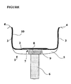
- the rim 1 comprises in particular a rim base 2 extended laterally by two wings 3.
- the radially outer ends of the wings 3 also include hooks 4.
- the bottom of the rim 2 covers a cavity 5 through which the spoke heads 6 to be fixed to the rim 1.
- the rim base still has as explained above orifices 7 to access the clamping nuts 8 to fix the heads of rays.
- a ribbon such as a thermoplastic strip or a textile reinforcing layer 9 is deposited on the bottom of the rim 2 to protect the sealing device according to the invention which in particular covers the rim bottom 2 having the orifices 7 on which the annular band 10 constituting the sealing device could come rub and damage especially during its implementation.
- a textile reinforcing layer is already known to protect the air chamber in a mounted assembly consisting of a rim, a tire and an air chamber.
- the annular band 10 forming the sealing device covers the surface of the rim base 2 and extends on either side on the surface of each of the flanges 3 facing each other substantially until each of hooks 4.
- the annular band 10 consists of a SIBS block elastomer ("Sibstar 102T" with a styrene content of about 15%, a Tg of about -65 ° C. and an Mn of about 90,000 g / mol) extended with about 66 phr of PIB oil ("Dynapak Poly 190" - Mn of the order of 1000 g / mol).
- the annular band is obtained by extrusion and then deposited on an interlayer.
- the strip thus obtained is cut to the desired length and the two ends are thermally welded to form a ring.
- the properties of the annular band 10 thus obtained will allow to set it up simply and accurately. Indeed, its elastic and hysteretic properties allow to stretch it to position precisely and see it take place on the bottom of rim 2 accurately. Its composition makes it effectively easy to deform and its return to the initial state is slow enough to allow precise positioning before this return takes place.
- the annular band 10 is thus deposited and centered on the rim 1 resting on the top of the hooks 4.
- the annular band 10 also has a sticky surface state that allows it when returning to the initial state to remain in contact wings 3 because of the friction between the annular band 10 and the surface of the wings 3. finally, as is shown in the figure, an annular band which extends from one wing to the other covering a part of their surfaces and the surface of the rim bottom2.
- Another solution may consist in producing the annular strip to co-extrude it with another material having a non-tacky surface state and intended to to come form the radially outer surface of the annular strip 10 after mounting on the rim 1. It may be for example a composition based on polyethylene, polypropylene, not affecting the deformability properties of the strip .
- An embodiment of a more complex device can still be envisaged by manufacturing by coextrusion a three-layer device comprising a central layer corresponding to the annular band described above, a radially outer layer made of a material having a non-surface state. adhesive and a radially inner layer of a thermoplastic material providing a protective function of the first layer with respect to the orifices of the rim or radius heads.
- the radially inner layer is then preferably axially narrower than the other layers so that the sticky surface state of the central layer allows when the device returns to its initial state, when it is mounted on the rim, to remain in contact with the rim flanges due to friction between said central layer and the wing surface.
- This valve may advantageously be associated with the annular band 10 during the manufacture of the latter. It can in particular be fixed by welding during the actual realization of the strip by welding the two ends of the strip obtained after the step of cutting the extruded profile.
- the mounting of the sealing device has been simple to implement and the addition of talc on the annular band once placed on the rim has made mounting the tire completely in accordance with a usual assembly.
- the assembled assembly was then inflated to 3 bars and kept static for 15 days. The pressure measured at the end of this period had not significantly changed.
Landscapes
- Engineering & Computer Science (AREA)
- Mechanical Engineering (AREA)
- Chemical & Material Sciences (AREA)
- Health & Medical Sciences (AREA)
- Chemical Kinetics & Catalysis (AREA)
- Medicinal Chemistry (AREA)
- Polymers & Plastics (AREA)
- Organic Chemistry (AREA)
- Materials Engineering (AREA)
- Tires In General (AREA)
- Sealing Material Composition (AREA)
Description
- L'invention concerne un dispositif d'étanchéité pour une jante prévue pour recevoir un pneumatique devant fonctionner sans chambre à air, c'est-à-dire un pneumatique de type « tubeless » et un procédé pour la mise en place du dispositif d'étanchéité sur la jante. L'invention vise également un ensemble monté constitué d'une roue comportant une telle jante associée au dispositif d'étanchéité et d'un pneumatique tubeless.
- L'invention vise plus particulièrement une jante non étanche prévue à l'origine pour recevoir un pneumatique prévu pour être monté avec une chambre à air, que l'on souhaite rendre étanche pour recevoir un pneumatique de type « tubeless » (montage sans chambre à air). L'invention s'applique toutefois également à une jante étanche sur laquelle on souhaiterait monter par exemple un pneumatique à zone basse peu ou pas étanche.
- Bien que non limité à ce type d'applications, l'invention sera plus particulièrement décrite en référence à une jante non étanche pour une roue à rayons pour bicyclette.
- Les roues de bicyclette sont le plus souvent constituées d'une jante reliée à un moyeu par des rayons. Ces rayons sont fixés à la jante par vissage d'écrous, ces écrous étant accessible depuis la surface radialement extérieure de la jante pour autoriser des réglages de tension des rayons. La jante comporte donc des orifices répartis sur sa périphérie pour autoriser la fixation des têtes de rayons qui une fois en place n'assure pas l'étanchéité desdits orifices.
- Lorsque la roue est destinée à être associée à un pneumatique et une chambre à air, la non étanchéité de la surface radialement extérieure de la jante ne pose aucun problème en mode de roulage non dégradé. La présence des têtes de rayons où des écrous de serrage nécessite toutefois la présente d'un ruban en fond de jante pour protéger la chambre à air lors de frottements ; les têtes de rayons ou les écrous pourraient dans le cas contraire provoquer une déchirure de la chambre à air.
- Il est par ailleurs connu de réaliser des ensembles montés de type tubeless pour bicyclettes. Il a déjà été décrit, dans la demande de brevet
EP 0 893 280 une jante de type tubeless. Ce type de jante permet de réaliser des montages de type tubeless qui présentent différents avantages ; tout d'abord, ils permettent de s'affranchir de la chambre à air, ce qui conduit à des gains en coût, en montage et en poids. Par ailleurs, l'absence de chambre à air permet de rendre l'ensemble monté moins sensible aux crevaisons par pincement ou par perforation. - Par contre, les coûts de fabrication de telles jantes sont beaucoup plus importants ce qui limite leur diffusion.
- Des solutions intermédiaires se sont développées pour permettre de réaliser des ensembles montés de type tubeless à coût réduit. De telles solutions ont par exemple été décrites dans les documents
US 4,108,232 etUS 2005/0189813 . Ces documents décrivent des dispositifs d'étanchéité prévus pour pouvoir être installés manuellement et qui consistent en une bande annulaire (ou « flap ») qui vient se loger au fond d'une jante et ainsi assurer l'étanchéité de ladite jante. De tels dispositifs sont peu onéreux et peuvent donc permettre la réalisation d'ensemble monté pour vélo de type tubeless en utilisant des jantes dites « tube type » et donc meilleur marché que les jantes tubeless évoquées précédemment. - Par contre, il s'avère que les différents dispositifs existants sont délicats à mettre en place notamment pour des raisons de centrage complexe qui peut conduire à une étanchéité imparfaite. Même pour un utilisateur expérimenté, ces solutions prévues pour transformer une jante tube type en jante tubeless restent très difficiles à mettre en oeuvre et ne sont donc que peu utilisées. En outre, les propriétés de ces bandes annulaires et notamment leur rigidité conduisent, lorsqu'elles ont pu être mises en place, à des microfuites dès lors que l'état de surface des jantes présente de légers reliefs tels que des soudures ou autres aspérités.
- Selon l'invention, on entend par « axiale », une direction parallèle à l'axe de rotation de la jante et par « radiale » une direction coupant l'axe de rotation de la jante et perpendiculaire à celui-ci. L'axe de rotation de la jante est l'axe autour duquel la jante tourne en utilisation normale. Le plan médian circonférentiel est un plan perpendiculaire à l'axe de rotation de la jante et qui divise la jante en deux moitiés. Un plan radial ou méridien est un plan qui contient l'axe de rotation de la jante.
- Les inventeurs se sont ainsi donnés pour mission de permettre la réalisation d'une jante notamment pour une roue non étanche, pouvant être associée à un pneumatique de type tubeless pour former un ensemble monté sans chambre à air, dont le coût est modéré et donc la réalisation est simple de mise en oeuvre.
- Ce but a été atteint selon l'invention par un dispositif d'étanchéité formant une bande annulaire destiné à être associé à une jante pour une roue, prévue pour recevoir un pneumatique, ladite jante étant constituée d'un fond de jante prolongé par deux ailes, pouvant comporter des crochets, ledit dispositif étant destiné à être mis en place pour couvrir au moins le fond de jante, la bande annulaire comprenant au moins une couche d'un matériau élastomérique comportant au moins un élastomère thermoplastique copolymère à blocs polystyrène et polyisobutylène (ci-après aussi dénommé "copolymère blocs" ou "élastomère blocs"), et une huile polybutène.
- Un tel copolymère blocs présente l'avantage majeur, en raison de sa nature thermoplastique, de pouvoir être travaillé tel quel à l'état fondu (liquide), et par conséquent d'offrir une possibilité de mise en oeuvre simplifiée, tandis que l'ajout de l'huile polybutène permet un abaissement du module et une augmentation du tack, sans pénalisation significative de l'étanchéité.
- Dans la présente description, sauf indication expresse différente, tous les pourcentages (%) indiqués sont des pourcentages en masse.
- D'autre part, tout intervalle de valeurs désigné par l'expression "entre a et b" représente le domaine de valeurs allant de plus de a à moins de b (c'est-à-dire bornes a et b exclues) tandis que tout intervalle de valeurs désigné par l'expression "de a à b" signifie le domaine de valeurs allant de a jusqu'à b (c'est-à-dire incluant les bornes strictes a et b).
- Par élastomère thermoplastique copolymère à blocs polystyrène et polyisobutylène (ou ci-après "copolymère blocs" ou "élastomère blocs"), doit être entendu tout copolymère thermoplastique comportant au moins un bloc polystyrène (c'est-à-dire un ou plusieurs blocs polystyrène) et au moins un bloc polyisobutylène (c'est-à-dire un ou plusieurs blocs polyisobutylène), auxquels peuvent être associés ou non d'autres blocs (par exemple polyéthylène et/ou polypropylène) et/ou d'autres unités monomères (par exemple des unités insaturées telles que diéniques).
- Préférentiellement, un tel copolymère blocs est un copolymère tribloc styrène/isobutylène/ styrène (en abrégé "SIBS").
- Par élastomère ou copolymère SIBS on entend dans la présente demande, par définition, tout élastomère tribloc styrène/ isobutylène/ styrène dans lequel le bloc central polyisobutylène peut être interrompu ou non par une ou plusieurs unités insaturées, en particulier une ou plusieurs unités diéniques telles qu'isopréniques, éventuellement halogénées.
- L'élastomère blocs tel que SIBS ci-dessus fait partie, de manière connue, de la famille des élastomères thermoplastiques (en abrégé "TPE"), plus précisément des élastomères thermoplastiques styréniques (en abrégé "TPS").
- On rappellera ici que les élastomères TPS se présentent généralement sous la forme de copolymères blocs à base de styrène. De structure intermédiaire entre polymères thermoplastiques et élastomères, ils sont constitués de séquences rigides polystyrène reliées par des séquences souples élastomère, par exemple polybutadiène, polyisoprène, poly(éthylène/butylène), ou encore polyisobutylène dans le cas par exemple de l'élastomère blocs tel que SIBS. Ce sont souvent des élastomères triblocs avec deux segments rigides reliés par un segment souple. Les segments rigides et souples peuvent être disposés linéairement, en étoile ou branchés. Typiquement, chacun de ces segments ou blocs contient au minimum plus de 5, généralement plus de 10 unités de base (par exemple styrène et isobutylène pour le SIBS).
- Selon un mode de réalisation préférentiel de l'invention, le taux pondéral de styrène, dans le copolymère blocs tel que SIBS, est compris entre 5% et 50%. En dessous du minimum indiqué, le caractère thermoplastique de l'élastomère blocs risque de diminuer de manière sensible tandis qu'au-dessus du maximum préconisé, l'élasticité de la couche étanche peut être affectée. Pour ces raisons, le taux de styrène est plus préférentiellement compris entre 10 et 40%, en particulier entre 10 et 30%.
- Par styrène, doit être entendu dans la présente description tout monomère à base de styrène, non substitué comme substitué ; parmi les styrènes substitués peuvent être cités par exemple les méthylstyrènes (par exemple α-méthylstyrène, β-méthylstyrène, p-méthylstyrène, tert-butylstyrène) les chlorostyrènes (par exemple monochlorostyrène, dichlorostyrène).
- On préfère que la température de transition vitreuse (Tg, mesurée selon ASTM D3418) de l'élastomère blocs soit inférieure à - 20°C, plus préférentiellement inférieure à - 40°C. Une valeur de Tg supérieure à ces minima peut diminuer les performances de la couche étanche lors d'une utilisation à très basse température ; pour une telle utilisation, la Tg de l'élastomère blocs est plus préférentiellement encore inférieure à - 50°C.
- La masse moléculaire moyenne en nombre (notée Mn) de l'élastomère blocs est préférentiellement comprise entre 30 000 et 500 000 g/mol, plus préférentiellement comprise entre 40 000 et 400 000 g/mol. En dessous des minima indiqués, la cohésion entre les chaînes d'élastomère blocs, notamment en raison de sa dilution par l'huile d'extension polybutène, risque d'être affectée ; d'autre part, une augmentation de la température d'usage risque d'affecter les propriétés mécaniques, notamment les propriétés à la rupture, avec pour conséquence une performance diminuée "à chaud". Par ailleurs, une masse Mn trop élevée peut être pénalisante pour la souplesse de la couche étanche aux gaz. Ainsi, on a constaté qu'une valeur comprise dans un domaine de 50 000 à 300 000 g/mol était particulièrement bien adaptée, notamment à une utilisation de la composition dans un bandage pneumatique.
- La masse moléculaire moyenne en nombre (Mn) de l'élastomère blocs est déterminée de manière connue, par chromatographie d'exclusion stérique (SEC). L'échantillon est préalablement solubilisé dans du tétrahydrofuranne à une concentration d'environ 1 g/l; puis la solution est filtrée sur filtre de porosité 0,45 µm avant injection. L'appareillage utilisé est une chaîne chromatographique "WATERS alliance". Le solvant d'élution est le tétrahydrofuranne, le débit de 0,7 ml/min, la température du système de 35°C et la durée d'analyse de 90 min. On utilise un jeu de quatre colonnes WATERS en série, de dénominations commerciales "STYRAGEL" ("HMW7", "HMW6E" et deux "HT6E"). Le volume injecté de la solution de l'échantillon de polymère est de 100 µl. Le détecteur est un réfractomètre différentiel "WATERS 2410" et son logiciel associé d'exploitation des données chromatographiques est le système "WATERS MILLENIUM". Les masses molaires moyennes calculées sont relatives à une courbe d'étalonnage réalisée avec des étalons de polystyrène.
- L'indice de polydispersité Ip (rappel : Ip = Mw/Mn avec Mw masse moléculaire moyenne en poids) de l'élastomère blocs est de préférence inférieur à 3 ; plus préférentiellement Ip est inférieur à 2.
- L'élastomère blocs, étendu avec l'huile polybutène, peut constituer à lui seul la couche élastomère étanche aux gaz ou bien être associé, dans cette couche élastomère, à d'autres élastomères.
- Si d'éventuels autres élastomères sont utilisés dans cette composition, l'élastomère blocs constitue l'élastomère majoritaire en poids ; il représente alors de préférence plus de 50%, plus préférentiellement plus de 70% en poids de l'ensemble des élastomères présents dans la composition ou couche élastomère. De tels élastomères complémentaires, minoritaires en poids, pourraient être par exemple des élastomères diéniques tels que du caoutchouc naturel ou un polyisoprène synthétique, un caoutchouc butyl ou des élastomères thermoplastiques styréniques (TPS) autres qu'un élastomère blocs tel que SIBS, dans la limite de la compatibilité de leurs microstructures.
- A titre d'élastomère TPS autre qu'un élastomère blocs tel que SIBS, utilisable en complément de ce dernier, peut être cité notamment un élastomère TPS choisi dans le groupe constitué par les copolymères blocs styrène/ butadiène/ styrène, les copolymères blocs styrène/ isoprène/ styrène, les copolymères blocs styrène/ isoprène/ butadiène/ styrène, les copolymères blocs styrène/ éthylène/ butylène/ styrène, les copolymères blocs styrène/éthylène/ propylène/ styrène, les copolymères blocs styrène/ éthylène/ éthylène/ propylène/styrène et les mélanges de ces copolymères. Plus préférentiellement, ledit élastomère TPS complémentaire éventuel est choisi dans le groupe constitué par les copolymères blocs styrène/ éthylène/ butylène/ styrène, les copolymères blocs styrène/ éthylène/ propylène/styrène et les mélanges de ces copolymères.
- Toutefois, selon un mode de réalisation préférentiel, l'élastomère blocs tel que SIBS est le seul élastomère, et le seul élastomère thermoplastique présent dans la composition ou couche élastomère étanche aux gaz.
- Les élastomères blocs tel que SIBS peuvent être mis en oeuvre de façon classique pour des TPE, par extrusion ou moulage, par exemple à partir d'une matière première disponible sous la forme de billes ou de granulés.
- Les élastomères SIBS par exemple sont disponibles commercialement, vendus par exemple par la société KANEKA sous la dénomination "SIBSTAR" (e.g. "Sibstar 102T", "Sibstar 103T" ou "Sibstar 073T"). Ils ont par exemple été décrits, ainsi que leur synthèse, dans les documents brevet
EP 731 112 US 4 946 899 ,US 5 260 383 . Ils ont été développés tout d'abord pour des applications biomédicales puis décrits dans diverses applications propres aux élastomères TPE, aussi variées que matériel médical, pièces pour automobile ou pour électroménager, gaines pour fils électriques, pièces d'étanchéité ou élastiques (voir par exempleEP 1 431 343 ,EP 1 561 783 ,EP 1 566 405 ,WO 2005/103146 ). - On utilise conformément à l'invention des huiles polybutènes, préférentiellement des huiles polyisobutylènes, qui ont démontré le meilleur compromis de propriétés comparativement aux autres huiles testées, notamment à des huiles conventionnelles du type paraffiniques. A température ambiante (23°C), ces huiles, plus ou moins visqueuses, sont des liquides (c'est-à-dire, pour rappel, des substances ayant la capacité de prendre à terme la forme de leur contenant), par opposition notamment à des résines ou des caoutchoucs qui sont par nature solides.
- A titre d'exemples, des huiles polyisobutylène sont commercialisées notamment par la société UNIVAR sous la dénomination "Dynapak Poly" (e.g. "Dynapak Poly 190"), par BASF sous les dénominations "Glissopal" (e.g. "Glissopal 1000") ou "Oppanol" (e.g. "Oppanol B 12").
- La masse moléculaire moyenne en nombre (Mn) de l'huile polybutène est préférentiellement comprise entre 200 et 25 000 g/mol, plus préférentiellement encore comprise entre 300 et 10 000 g/mol. Pour des masses Mn trop basses, il existe un risque de migration de l'huile à l'extérieur de la composition, tandis que des masses trop élevées ne diminuent pas suffisamment le module.
- La masse moléculaire moyenne en nombre (Mn) de l'huile polybutène est déterminée par SEC, l'échantillon étant préalablement solubilisé dans du tétrahydrofuranne à une concentration d'environ 1 g/l; puis la solution est filtrée sur filtre de porosité 0,45µm avant injection. L'appareillage est la chaîne chromatographique "WATERS alliance". Le solvant d'élution est le tétrahydrofuranne, le débit de 1 ml/min, la température du système de 35°C et la durée d'analyse de 30 min. On utilise un jeu de deux colonnes "WATERS" de dénomination "STYRAGEL HT6E". Le volume injecté de la solution de l'échantillon de polymère est de 100 µl. Le détecteur est un réfractomètre différentiel "WATERS 2410" et son logiciel associé d'exploitation des données chromatographiques est le système "WATERS MILLENIUM". Les masses molaires moyennes calculées sont relatives à une courbe d'étalonnage réalisée avec des étalons de polystyrène.
- On préfère que le taux d'huile polybutène soit supérieur à 5 pce, de préférence compris entre 5 et 100 pce (parties en poids pour cent parties d'élastomère total, c'est-à-dire élastomère blocs tel que SIBS plus tout autre élastomère ou TPE éventuel présent).
- En dessous du minimum indiqué, la bande annulaire risque de présenter une rigidité trop forte pour certaines applications tandis qu'au-delà du maximum préconisé, on s'expose à un risque de cohésion insuffisante de la composition et de perte d'étanchéité pouvant être néfaste selon l'application considérée.
- Pour ces raisons, on préfère que le taux d'huile polybutène soit supérieur à 10 pce, notamment compris entre 10 et 90 pce, plus préférentiellement encore qu'il soit supérieur à 20 pce, notamment compris entre 20 et 80 pce.
- La bande annulaire décrite ci-dessus peut comporter par ailleurs les divers additifs usuellement présents dans les couches étanches à l'air connues de l'homme du métier. On citera par exemple des charges renforçantes telles que du noir de carbone ou de la silice, des charges non renforçantes ou inertes, des agents colorants avantageusement utilisables pour la coloration de la composition, des charges lamellaires améliorant encore l'étanchéité (e.g. des phyllosilicates tels que kaolin, talc, mica, du graphite, des argiles ou argiles modifiées ("organo clays")), des plastifiants autres que les huiles d'extension précitées, des agents de protection tels que antioxydants ou antiozonants, anti-UV, divers agents de mise en oeuvre ou autres stabilisants, ou encore des promoteurs aptes à favoriser l'adhésion au reste de la structure de l'objet pneumatique.
- Outre les élastomères (élastomères blocs tels que SIBS et autres élastomères éventuels) précédemment décrits, la bande annulaire pourrait aussi comporter, toujours selon une fraction pondérale minoritaire par rapport à l'élastomère blocs, des polymères autres que des élastomères, tels que par exemple des polymères thermoplastiques compatibles avec l'élastomère blocs.
- La bande annulaire précédemment décrite est un composé solide (à 23°C) et élastique, qui se caractérise notamment, grâce à sa formulation spécifique, par une très haute souplesse et très haute déformabilité.
- Selon un mode de réalisation préférentiel de l'invention, cette bande annulaire présente un module sécant en extension, à 10% d'allongement (noté M 10), qui est inférieur à 2 MPa, plus préférentiellement inférieur à 1,5 MPa (notamment inférieur à 1 MPa). Cette grandeur est mesurée en première élongation (c'est-à-dire sans cycle d'accommodation) à une température de 23°C, avec une vitesse de traction de 500 mm/min (norme ASTM D412), et rapportée à la section initiale de l'éprouvette.
- Selon un mode de réalisation préféré de l'invention, la bande annulaire présente une largeur sensiblement égale à la longueur curviligne dans un plan méridien comprise entre les points radialement les plus extérieurs de chacune des ailes.
- Selon cette réalisation préférée de l'invention, la bande annulaire peut être mise en place pour couvrir la surface radialement extérieure de la jante depuis le sommet radialement extérieur d'une aile au sommet de l'autre.
- Avantageusement encore selon l'invention, la bande annulaire présente un diamètre sensiblement égal au diamètre du fond de jante. La combinaison des propriétés élastiques et du tack associés à un tel diamètre permet de mettre en place la bande annulaire de sorte qu'elle couvre correctement la surface radialement extérieure de la jante.
- Les essais réalisés avec le dispositif ainsi réalisé selon l'invention ont montré que la bande annulaire permet d'obtenir une étanchéité parfaite quel que soit l'état de surface de la jante sur laquelle elle est mise en place. En effet ses propriétés d'étanchéité, sa souplesse et sa faible dureté autorisent une bonne étanchéité malgré la présence d'éventuelles aspérités sur la surface de la jante, ladite bande annulaire venant épouser la surface de la jante.
- En outre, le dispositif d'étanchéité selon l'invention est simple à réaliser. Le matériau constituant la bande annulaire peut être extrudé et mis en forme sur un profilé, par exemple plat. La bande ainsi obtenue est découpée à la longueur souhaitée et les deux extrémités sont soudées par tous moyens connus de l'homme du métier tels que des moyens thermiques et/ou chimiques et/ou application d'une dissolution de polymère.
- Une variante avantageuse de réalisation de l'invention prévoit que la bande annulaire comprend une deuxième couche d'un matériau thermoplastique radialement intérieure à la couche d'un matériau élastomérique comportant au moins un élastomère thermoplastique copolymère à blocs polystyrène et polyisobutylène, et une huile polybutène. Cette deuxième couche va avantageusement jouer le rôle du ruban de fond de jante, décrit précédemment, qui vient couvrir les orifices répartis sur la périphérie de la jante pour autoriser la fixation des têtes de rayons.
- Le matériau thermoplastique est par exemple un polypropylène mélangé à un matériau de type SEBS, SEPS ou SEEPS afin d'obtenir une déformabilité adéquate.
- Avantageusement encore, la deuxième couche radialement intérieure présente une largeur inférieure à la longueur curviligne dans un plan méridien comprise entre les points radialement les plus extérieurs de chacune des ailes. Selon une telle réalisation, la deuxième couche apporte une fonction de protection de la première couche à l'égard des orifices de la jante ou bien des têtes de rayon et la deuxième couche radialement intérieure étant plus étroite que la couche d'un matériau élastomérique comportant au moins un élastomère thermoplastique copolymère à blocs polystyrène et polyisobutylène, et une huile polybutène, cette dernière autorisant toujours une mise en place aisée sur la jante par la combinaison de ses propriétés élastiques et de son tack.
- Selon cette variante de réalisation de l'invention, le ruban usuellement placé en fond de jante pour protéger la chambre à air de frottements contre les têtes de rayons, les écrous ou les bords des orifices de la jante et qui peut apparaître utile pour protéger dans le cas de l'invention la couche d'un matériau élastomérique comportant au moins un élastomère thermoplastique copolymère à blocs polystyrène et polyisobutylène, et une huile polybutène est associé à ladite couche lors de sa fabrication et peut donc être mis en place simultanément sur la jante. Une telle variante peut donc être plus simple de mise en oeuvre lors de la mise en place du dispositif d'étanchéité sur la jante si un « ruban de protection » apparaît nécessaire.
- L'invention propose également un ensemble monté constitué essentiellement d'une roue comprenant une jante et d'un pneumatique tubeless, la jante étant associée à un dispositif d'étanchéité tel que décrit précédemment.
- L'ensemble monté selon l'invention est avantageusement constitué d'une roue comprenant une jante non étanche.
- L'invention propose encore un procédé de mise en place d'un dispositif d'étanchéité tel que décrit précédemment sur une jante pour une roue prévue pour recevoir un pneumatique, ladite jante étant constituée d'un fond de jante prolongé par deux ailes, la bande annulaire étant étirée élastiquement pour être déposée sur les points radialement les plus extérieurs de chacune des ailes.
- Comme expliqué précédemment, les propriétés élastiques permettent d'augmenter le diamètre de la bande qui peut être mise en place aisément en appui sur les points radialement les plus extérieurs de chacune des ailes et le tack de ladite bande lui permet de reprendre partiellement sa taille initiale alors que ses bords restent par frottement sur les ailes de la jante. Par ailleurs, les propriétés hystérétiques relativement élevées de la bande annulaire garantissent un retour à la taille initiale relativement lent qui va permettre de bien positionner la bande annulaire relativement au fond de jante et notamment permettre un bon centrage.
- D'autres détails et caractéristiques avantageux de l'invention ressortiront ci-après de la description d'un exemple de réalisation de l'invention en référence à la figure qui représente un schéma d'une vue en coupe radiale d'un schéma d'une jante selon l'invention.
- La figure n'est pas représentée à l'échelle pour en simplifier la compréhension.
- La figure représente schématiquement un profil en coupe radiale d'une jante 1 pour bicyclette. La jante 1 comprend notamment un fond de jante 2 prolongé latéralement par deux ailes 3. Les extrémités radialement extérieures des ailes 3 comportent encore des crochets 4.
- Le fond de jante 2 coiffe une cavité 5 dans laquelle passe les têtes de rayons 6 pour être fixées à la jante 1. le fond de jante présente encore comme expliqué précédemment des orifices 7 permettant d'accéder aux écrous de serrage 8 pour fixer les têtes de rayons.
- Un ruban tel qu'une bande thermoplastique ou une couche de renfort textile 9 est déposée sur le fond de jante 2 pour protéger le dispositif d'étanchéité selon l'invention qui vient notamment couvrir le fond de jante 2 comportant les orifices 7 sur lesquelles la bande annulaire 10 constituant le dispositif d'étanchéité pourrait venir frotter et s'abîmer notamment lors de sa mise en place. Comme expliqué précédemment une telle couche de renfort textile est déjà connue pour protéger la chambre à air dans un ensemble monté constitué d'une jante, un pneumatique et une chambre à air.
- La bande annulaire 10 formant le dispositif d'étanchéité couvre la surface du fond de jante 2 et s'étend de part et d'autre sur la surface de chacune des ailes 3 en regard l'une de l'autre sensiblement jusqu'à chacun de crochets 4.
- La bande annulaire 10 conforme à l'invention est constituée d'un élastomère blocs SIBS ("Sibstar 102T" avec un taux de styrène d'environ 15%, une Tg d'environ - 65°C et une Mn d'environ 90 000 g/mol) étendu avec environ 66 pce d'huile PIB ("Dynapak Poly 190" - Mn de l'ordre de 1000 g/mol).
- La bande annulaire est obtenue par extrusion puis déposée sur un intercalaire. La bande ainsi obtenue est découpée à la longueur souhaitée et les deux extrémités sont soudées thermiquement pour former un anneau.
- Les propriétés de la bande annulaire 10 ainsi obtenue vont permettre de la mettre en place de manière simple et précise. En effet, ses propriétés élastiques et hystérétiques permettent de l'étirer de la positionner précisément et de la voir prendre place sur le fond de jante 2 de manière précise. Sa composition la rend effectivement facile à déformer et son retour à l'état initial est suffisamment lent pour autoriser un positionnement précis avant que ce retour n'ait lieu. La bande annulaire 10 est ainsi déposée et centrée sur la jante 1 en appui sur le sommet des crochets 4. La bande annulaire 10 présente en outre un état de surface collant qui lui permet lors de son retour à l'état initial de rester au contact des ailes 3 du fait du frottement qui s'exerce entre la bande annulaire 10 et la surface des ailes 3. on obtient finalement comme il apparaît sur la figure une bande annulaire qui s'étend d'une aile à l'autre en couvrant une partie de leurs surfaces et la surface du fond de jante2.
- Les propriétés en termes de rigidité permettent en outre d'absorber toutes les irrégularités de surface de la jante 1 et conduit ainsi à une étanchéité complète sans apparition d'aucune micro-fuite comme il peut en exister avec des dispositifs existants comme il l'a été rappelé précédemment.
- L'association du dispositif d'étanchéité et de la jante 1 étant effectuée, il est ensuite possible de monter un pneumatique dit « tubeless » sur la jante. La bande annulaire présentant un état de surface collant ou « tack », pour faciliter le montage du pneumatique il est préférable de rendre plus glissante la surface de la bande annulaire 10 sur laquelle le pneumatique doit venir glisser pour se monter. Cet état glissant peut par exemple être obtenu en mettant du talc avant l'étape de montage du pneumatique.
- Une autre solution peut consister lors de la réalisation de la bande annulaire à co-extruder celle-ci avec un autre matériau présentant un état de surface non collant et destiné à venir former la surface radialement extérieure de la bande annulaire 10 après montage sur la jante 1. Il peut s'agir par exemple d'une composition à base de polyéthylène, de polypropylène, n'influant pas sur les propriétés de déformabilité de la bande.
- Une réalisation d'un dispositif plus complexe est encore envisageable en fabriquant par co-extrusion un dispositif à trois couches comportant une couche centrale correspondant à la bande annulaire décrite ci-dessus, une couche radialement extérieure réalisée avec un matériau présentant un état de surface non collant et une couche radialement intérieure d'un matériau thermoplastique apportant une fonction de protection de la première couche à l'égard des orifices de la jante ou bien des têtes de rayon. La couche radialement intérieure est alors de préférence axialement plus étroite que les autres couches de sorte que l'état de surface collant de la couche centrale permette lors du retour à l'état initial du dispositif, lors de son montage sur la jante, de rester au contact des ailes de la jante du fait du frottement qui s'exerce entre ladite couche centrale et la surface des ailes.
- La bande annulaire 10 couvrant la surface du fond de jante 2 pour assurer l'étanchéité de ladite jante 2, il est également nécessaire de prévoir la présence d'une valve devant traverser le fond de jante 2 et la bande annulaire 10 pour permettre le gonflage de l'ensemble monté. Cette valve peut avantageusement être associée à la bande annulaire 10 lors de la fabrication de cette dernière. Elle peut notamment être fixée par soudage lors de la réalisation proprement dite de la bande par soudure des deux extrémités de la bande obtenue après l'étape de découpe du profilé extrudé.
- Des essais de montage et de roulage ont été réalisés avec ce type d'ensemble monté dans une dimension VTT 47-559 sur une jante de 559 selon une technologie « tubeless ».
- Le montage du dispositif d'étanchéité s'est avéré simple de mise en oeuvre et l'ajout de talc sur la bande annulaire une fois placée sur la jante a rendu le montage du pneumatique tout à fait conforme à un montage usuel.
- L'ensemble monté a ensuite été gonflé à 3 bars et conservé 15 jours en statique. La pression mesurée à l'issue de cette période n'avait pas significativement changé.
- Des essais en roulage sur route et sur chemin n'ont par ailleurs laissé apparaître aucune défaillance de l'ensemble monté ainsi constitué selon l'invention.
Claims (15)
- Dispositif d'étanchéité formant une bande annulaire destiné à être associé à une jante pour une roue prévue pour recevoir un pneumatique, ladite jante étant constituée d'un fond de jante prolongé par deux ailes, ledit dispositif étant destiné à être mis en place pour couvrir au moins le fond de jante, caractérisée en ce que la bande annulaire comprend au moins une couche d'un matériau élastomérique comportant au moins un élastomère thermoplastique copolymère à blocs polystyrène et polyisobutylène, et une huile polybutène.
- Dispositif selon la revendication 1, caractérisée en ce le copolymère blocs est un copolymère styrène/ isobutylène/ styrène (en abrégé "SIBS").
- Dispositif selon la revendication 1 ou 2, caractérisée en ce que le copolymère blocs comprend entre 5 et 50% en masse de styrène.
- Dispositif selon l'une des revendications 1 à 3, caractérisée en ce que la Tg du copolymère blocs est inférieure à - 20°C.
- Dispositif selon l'une des revendications précédentes, caractérisée en ce que la masse moléculaire moyenne en nombre (Mn) du copolymère blocs est comprise entre 30 000 et 500 000 g/mol.
- Dispositif selon l'une des revendications précédentes, caractérisée en ce que l'huile polybutène est une huile polyisobutylène.
- Dispositif selon l'une des revendications précédentes, caractérisée en ce que la masse moléculaire moyenne en nombre (Mn) de l'huile polybutène est comprise entre 200 et 25 000 g/mol.
- Dispositif selon l'une des revendications précédentes, caractérisée en ce que le taux d'huile polybutène est supérieur à 5 pce, de préférence compris entre 5 et 100 pce (pce = parties en poids pour cent parties d'élastomère).
- Dispositif selon l'une des revendications précédentes, caractérisée en ce que la bande annulaire présente une largeur sensiblement égale à la longueur curviligne dans un plan méridien comprise entre les points radialement les plus extérieurs de chacune des ailes.
- Dispositif selon l'une des revendications précédentes, caractérisée en ce que la bande annulaire présente un diamètre sensiblement égal au diamètre du fond de jante.
- Dispositif selon l'une des revendications précédentes, caractérisée en ce que la bande annulaire comprend une deuxième couche d'un matériau thermoplastique radialement intérieure à la couche d'un matériau élastomérique comportant au moins un élastomère thermoplastique copolymère à blocs polystyrène et polyisobutylène, et une huile polybutène.
- Dispositif selon l'une des revendications précédentes, caractérisée en ce que la deuxième couche radialement intérieure présente une largeur inférieure à la longueur curviligne dans un plan méridien comprise entre les points radialement les plus extérieurs de chacune des ailes.
- Ensemble monté constitué essentiellement d'une roue comprenant une jante et d'un pneumatique « tubeless », la jante étant associée à un dispositif d'étanchéité selon l'une des revendications 1 à 12.
- Ensemble monté selon la revendication 13, caractérisé en ce qu'il est constitué d'une roue comprenant une jante non étanche.
- Procédé de mise en place d'un dispositif d'étanchéité selon l'une des revendications 1 à 12 sur une jante pour une roue prévue pour recevoir un pneumatique, ladite jante étant constituée d'un fond de jante prolongé par deux ailes caractérisé en ce que la bande annulaire est étirée élastiquement et en ce qu'elle est déposée sur les points radialement les plus extérieurs de chacune des ailes.
Applications Claiming Priority (2)
| Application Number | Priority Date | Filing Date | Title |
|---|---|---|---|
| FR0854754A FR2933636B1 (fr) | 2008-07-11 | 2008-07-11 | Dispositif d'etancheite et procede de mise en place dudit dispositif sur une jante |
| PCT/EP2009/005005 WO2010003679A1 (fr) | 2008-07-11 | 2009-07-10 | Dispositif d'etancheite et procede de mise en place dudit dispositif sur une jante |
Publications (2)
| Publication Number | Publication Date |
|---|---|
| EP2300531A1 EP2300531A1 (fr) | 2011-03-30 |
| EP2300531B1 true EP2300531B1 (fr) | 2012-11-28 |
Family
ID=40394166
Family Applications (1)
| Application Number | Title | Priority Date | Filing Date |
|---|---|---|---|
| EP09793890A Active EP2300531B1 (fr) | 2008-07-11 | 2009-07-10 | Dispositif d'etancheite et procede de mise en place dudit dispositif sur une jante |
Country Status (6)
| Country | Link |
|---|---|
| US (1) | US8826954B2 (fr) |
| EP (1) | EP2300531B1 (fr) |
| CN (1) | CN102083903B (fr) |
| ES (1) | ES2400051T3 (fr) |
| FR (1) | FR2933636B1 (fr) |
| WO (1) | WO2010003679A1 (fr) |
Families Citing this family (2)
| Publication number | Priority date | Publication date | Assignee | Title |
|---|---|---|---|---|
| WO2017127029A1 (fr) * | 2016-01-22 | 2017-07-27 | N.D. Rubber Public Company Limited | Tampon d'étanchéification permettant d'empêcher les fuites d'air d'un pneumatique de véhicule |
| EP3504070A4 (fr) * | 2016-08-29 | 2020-04-29 | Christian Feucht | Jante à gorge encastrée et appareil et système de ruban de fond de jante |
Family Cites Families (13)
| Publication number | Priority date | Publication date | Assignee | Title |
|---|---|---|---|---|
| JPS5273401A (en) * | 1975-12-11 | 1977-06-20 | Sumitomo Rubber Ind | Pneumatic tire with adhesive puncture sealing layer |
| US4359078A (en) * | 1979-03-14 | 1982-11-16 | The Goodyear Tire & Rubber Company | Pneumatic tire having puncture sealing feature and method of making same |
| US4895610A (en) * | 1983-08-15 | 1990-01-23 | The Goodyear Tire & Rubber Company | Self-sealing pneumatic tire and method of manufacturing the same |
| US4928741A (en) * | 1986-11-14 | 1990-05-29 | The Goodyear Tire & Rubber Company | Rubber tire having polyvinylidene chloride/elastomer inner liner coating |
| EP0586547B1 (fr) * | 1991-05-24 | 1995-09-13 | The Dow Chemical Company | Couches d'arret en elastomere pour pneus |
| AU675646B2 (en) * | 1992-05-13 | 1997-02-13 | Raychem Limited | Gels |
| EP0774340B1 (fr) * | 1995-05-02 | 2002-07-24 | The Yokohama Rubber Co., Ltd. | Procede de production de pneumatiques |
| WO2003029029A1 (fr) * | 2001-09-05 | 2003-04-10 | The Yokohama Rubber Co., Ltd. | Pneumatique pouvant rouler a plat |
| US6837287B2 (en) * | 2002-06-13 | 2005-01-04 | The Goodyear Tire & Rubber Company | Self-sealing pneumatic tire and preparation thereof |
| WO2005017013A1 (fr) * | 2003-08-01 | 2005-02-24 | Exxonmobil Chemical Patents, Inc. | Composition elastomere a faible permeabilite |
| CN100480348C (zh) * | 2003-10-17 | 2009-04-22 | 琳得科株式会社 | 轮胎粘贴片及轮胎粘贴片的制造方法 |
| FR2910382B1 (fr) * | 2006-12-22 | 2009-03-06 | Michelin Soc Tech | Pneumatique avec une couche auto-obturante |
| FR2910478B1 (fr) * | 2006-12-22 | 2009-03-06 | Michelin Soc Tech | Composition auto-obturante pour objet pneumatique |
-
2008
- 2008-07-11 FR FR0854754A patent/FR2933636B1/fr not_active Expired - Fee Related
-
2009
- 2009-07-10 US US13/002,947 patent/US8826954B2/en active Active
- 2009-07-10 CN CN200980126331.7A patent/CN102083903B/zh active Active
- 2009-07-10 WO PCT/EP2009/005005 patent/WO2010003679A1/fr not_active Ceased
- 2009-07-10 ES ES09793890T patent/ES2400051T3/es active Active
- 2009-07-10 EP EP09793890A patent/EP2300531B1/fr active Active
Also Published As
| Publication number | Publication date |
|---|---|
| US20110181100A1 (en) | 2011-07-28 |
| CN102083903B (zh) | 2013-05-22 |
| FR2933636B1 (fr) | 2011-09-02 |
| ES2400051T3 (es) | 2013-04-05 |
| EP2300531A1 (fr) | 2011-03-30 |
| US8826954B2 (en) | 2014-09-09 |
| CN102083903A (zh) | 2011-06-01 |
| WO2010003679A1 (fr) | 2010-01-14 |
| FR2933636A1 (fr) | 2010-01-15 |
Similar Documents
| Publication | Publication Date | Title |
|---|---|---|
| EP2303563B1 (fr) | Composition elastomere auto-obturante | |
| EP2303562B1 (fr) | Stratifie etanche a l'air et anticrevaison pour objet pneumatique | |
| EP2209608B1 (fr) | Objet pneumatique pourvu d'une composition auto-obturante | |
| EP2125949B1 (fr) | Objet pneumatique | |
| EP2152529B1 (fr) | Objet pneumatique pourvu d'une couche étanche aux gaz a base d'un élastomère thermoplastique | |
| EP2167332B1 (fr) | Stratifie multicouches et anche aux gaz et anti-crevaison et objet pneumatique le comportant | |
| EP2373476B1 (fr) | Objet pneumatique pourvu d'une couche auto-obturante et etanche aux gaz, a base d'elastomere thermoplastique et d'une huile d'extension | |
| EP2167328B1 (fr) | Objet pneumatique pourvu d'une couche etanche aux gaz a base d'un elastomere thermoplastique et d'une charge lamellaire | |
| WO2009112233A1 (fr) | Chambre a air pour bandage pneumatique a base d'un elastomere thermoplastique | |
| WO2008145277A1 (fr) | Objet pneumatique pourvu d'une couche etanche aux gaz a base d'un elastomere thermoplastique et d'une huile polybutene | |
| FR2917996A1 (fr) | Pneumatique avec une couche auto-obturante. | |
| EP2373486A1 (fr) | Stratifie multicouche etanche a l'air pour objet pneumatique | |
| FR2966081A1 (fr) | Bandage pneumatique comprenant une couche auto-obturante a gradient radial de fluage | |
| EP2373740A1 (fr) | Objet pneumatique pourvu d'une couche etanche aux gaz a base de deux elastomeres thermoplastiques | |
| FR2969536A1 (fr) | Valve auto-obturante | |
| EP2300531B1 (fr) | Dispositif d'etancheite et procede de mise en place dudit dispositif sur une jante | |
| WO2018229389A1 (fr) | Compositions auto-obturantes | |
| WO2018229390A1 (fr) | Compositions auto-obturantes | |
| FR3103491A1 (fr) | Composition auto-obturante pour objet pneumatique |
Legal Events
| Date | Code | Title | Description |
|---|---|---|---|
| PUAI | Public reference made under article 153(3) epc to a published international application that has entered the european phase |
Free format text: ORIGINAL CODE: 0009012 |
|
| 17P | Request for examination filed |
Effective date: 20110211 |
|
| AK | Designated contracting states |
Kind code of ref document: A1 Designated state(s): AT BE BG CH CY CZ DE DK EE ES FI FR GB GR HR HU IE IS IT LI LT LU LV MC MK MT NL NO PL PT RO SE SI SK SM TR |
|
| AX | Request for extension of the european patent |
Extension state: AL BA RS |
|
| DAX | Request for extension of the european patent (deleted) | ||
| REG | Reference to a national code |
Ref country code: DE Ref legal event code: R079 Ref document number: 602009011618 Country of ref document: DE Free format text: PREVIOUS MAIN CLASS: C08L0023200000 Ipc: B60B0021060000 |
|
| GRAP | Despatch of communication of intention to grant a patent |
Free format text: ORIGINAL CODE: EPIDOSNIGR1 |
|
| RIC1 | Information provided on ipc code assigned before grant |
Ipc: B60C 1/00 20060101AFI20120612BHEP |
|
| RIC1 | Information provided on ipc code assigned before grant |
Ipc: C08L 23/20 20060101ALI20120618BHEP Ipc: C08L 53/00 20060101ALI20120618BHEP Ipc: B60B 21/06 20060101AFI20120618BHEP |
|
| RAP1 | Party data changed (applicant data changed or rights of an application transferred) |
Owner name: COMPAGNIE GENERALE DES ETABLISSEMENTS MICHELIN Owner name: MICHELIN RECHERCHE ET TECHNIQUE S.A. |
|
| GRAS | Grant fee paid |
Free format text: ORIGINAL CODE: EPIDOSNIGR3 |
|
| GRAA | (expected) grant |
Free format text: ORIGINAL CODE: 0009210 |
|
| AK | Designated contracting states |
Kind code of ref document: B1 Designated state(s): AT BE BG CH CY CZ DE DK EE ES FI FR GB GR HR HU IE IS IT LI LT LU LV MC MK MT NL NO PL PT RO SE SI SK SM TR |
|
| REG | Reference to a national code |
Ref country code: GB Ref legal event code: FG4D Free format text: NOT ENGLISH |
|
| REG | Reference to a national code |
Ref country code: CH Ref legal event code: EP |
|
| REG | Reference to a national code |
Ref country code: AT Ref legal event code: REF Ref document number: 585942 Country of ref document: AT Kind code of ref document: T Effective date: 20121215 |
|
| REG | Reference to a national code |
Ref country code: IE Ref legal event code: FG4D Free format text: LANGUAGE OF EP DOCUMENT: FRENCH |
|
| REG | Reference to a national code |
Ref country code: DE Ref legal event code: R096 Ref document number: 602009011618 Country of ref document: DE Effective date: 20130124 |
|
| REG | Reference to a national code |
Ref country code: NL Ref legal event code: T3 |
|
| REG | Reference to a national code |
Ref country code: ES Ref legal event code: FG2A Ref document number: 2400051 Country of ref document: ES Kind code of ref document: T3 Effective date: 20130405 |
|
| REG | Reference to a national code |
Ref country code: AT Ref legal event code: MK05 Ref document number: 585942 Country of ref document: AT Kind code of ref document: T Effective date: 20121128 |
|
| REG | Reference to a national code |
Ref country code: LT Ref legal event code: MG4D |
|
| PG25 | Lapsed in a contracting state [announced via postgrant information from national office to epo] |
Ref country code: FI Free format text: LAPSE BECAUSE OF FAILURE TO SUBMIT A TRANSLATION OF THE DESCRIPTION OR TO PAY THE FEE WITHIN THE PRESCRIBED TIME-LIMIT Effective date: 20121128 Ref country code: SE Free format text: LAPSE BECAUSE OF FAILURE TO SUBMIT A TRANSLATION OF THE DESCRIPTION OR TO PAY THE FEE WITHIN THE PRESCRIBED TIME-LIMIT Effective date: 20121128 Ref country code: NO Free format text: LAPSE BECAUSE OF FAILURE TO SUBMIT A TRANSLATION OF THE DESCRIPTION OR TO PAY THE FEE WITHIN THE PRESCRIBED TIME-LIMIT Effective date: 20130228 Ref country code: LT Free format text: LAPSE BECAUSE OF FAILURE TO SUBMIT A TRANSLATION OF THE DESCRIPTION OR TO PAY THE FEE WITHIN THE PRESCRIBED TIME-LIMIT Effective date: 20121128 |
|
| PG25 | Lapsed in a contracting state [announced via postgrant information from national office to epo] |
Ref country code: GR Free format text: LAPSE BECAUSE OF FAILURE TO SUBMIT A TRANSLATION OF THE DESCRIPTION OR TO PAY THE FEE WITHIN THE PRESCRIBED TIME-LIMIT Effective date: 20130301 Ref country code: PL Free format text: LAPSE BECAUSE OF FAILURE TO SUBMIT A TRANSLATION OF THE DESCRIPTION OR TO PAY THE FEE WITHIN THE PRESCRIBED TIME-LIMIT Effective date: 20121128 Ref country code: PT Free format text: LAPSE BECAUSE OF FAILURE TO SUBMIT A TRANSLATION OF THE DESCRIPTION OR TO PAY THE FEE WITHIN THE PRESCRIBED TIME-LIMIT Effective date: 20130328 Ref country code: LV Free format text: LAPSE BECAUSE OF FAILURE TO SUBMIT A TRANSLATION OF THE DESCRIPTION OR TO PAY THE FEE WITHIN THE PRESCRIBED TIME-LIMIT Effective date: 20121128 Ref country code: SI Free format text: LAPSE BECAUSE OF FAILURE TO SUBMIT A TRANSLATION OF THE DESCRIPTION OR TO PAY THE FEE WITHIN THE PRESCRIBED TIME-LIMIT Effective date: 20121128 |
|
| PG25 | Lapsed in a contracting state [announced via postgrant information from national office to epo] |
Ref country code: AT Free format text: LAPSE BECAUSE OF FAILURE TO SUBMIT A TRANSLATION OF THE DESCRIPTION OR TO PAY THE FEE WITHIN THE PRESCRIBED TIME-LIMIT Effective date: 20121128 |
|
| PG25 | Lapsed in a contracting state [announced via postgrant information from national office to epo] |
Ref country code: DK Free format text: LAPSE BECAUSE OF FAILURE TO SUBMIT A TRANSLATION OF THE DESCRIPTION OR TO PAY THE FEE WITHIN THE PRESCRIBED TIME-LIMIT Effective date: 20121128 Ref country code: BG Free format text: LAPSE BECAUSE OF FAILURE TO SUBMIT A TRANSLATION OF THE DESCRIPTION OR TO PAY THE FEE WITHIN THE PRESCRIBED TIME-LIMIT Effective date: 20130228 Ref country code: EE Free format text: LAPSE BECAUSE OF FAILURE TO SUBMIT A TRANSLATION OF THE DESCRIPTION OR TO PAY THE FEE WITHIN THE PRESCRIBED TIME-LIMIT Effective date: 20121128 Ref country code: CZ Free format text: LAPSE BECAUSE OF FAILURE TO SUBMIT A TRANSLATION OF THE DESCRIPTION OR TO PAY THE FEE WITHIN THE PRESCRIBED TIME-LIMIT Effective date: 20121128 Ref country code: SK Free format text: LAPSE BECAUSE OF FAILURE TO SUBMIT A TRANSLATION OF THE DESCRIPTION OR TO PAY THE FEE WITHIN THE PRESCRIBED TIME-LIMIT Effective date: 20121128 |
|
| PG25 | Lapsed in a contracting state [announced via postgrant information from national office to epo] |
Ref country code: RO Free format text: LAPSE BECAUSE OF FAILURE TO SUBMIT A TRANSLATION OF THE DESCRIPTION OR TO PAY THE FEE WITHIN THE PRESCRIBED TIME-LIMIT Effective date: 20121128 |
|
| PLBE | No opposition filed within time limit |
Free format text: ORIGINAL CODE: 0009261 |
|
| STAA | Information on the status of an ep patent application or granted ep patent |
Free format text: STATUS: NO OPPOSITION FILED WITHIN TIME LIMIT |
|
| 26N | No opposition filed |
Effective date: 20130829 |
|
| PG25 | Lapsed in a contracting state [announced via postgrant information from national office to epo] |
Ref country code: CY Free format text: LAPSE BECAUSE OF FAILURE TO SUBMIT A TRANSLATION OF THE DESCRIPTION OR TO PAY THE FEE WITHIN THE PRESCRIBED TIME-LIMIT Effective date: 20121128 |
|
| REG | Reference to a national code |
Ref country code: DE Ref legal event code: R097 Ref document number: 602009011618 Country of ref document: DE Effective date: 20130829 |
|
| BERE | Be: lapsed |
Owner name: CIE GENERALE DES ETABLISSEMENTS MICHELIN Effective date: 20130731 Owner name: MICHELIN RECHERCHE ET TECHNIQUE S.A. Effective date: 20130731 |
|
| PG25 | Lapsed in a contracting state [announced via postgrant information from national office to epo] |
Ref country code: HR Free format text: LAPSE BECAUSE OF FAILURE TO SUBMIT A TRANSLATION OF THE DESCRIPTION OR TO PAY THE FEE WITHIN THE PRESCRIBED TIME-LIMIT Effective date: 20130731 |
|
| PG25 | Lapsed in a contracting state [announced via postgrant information from national office to epo] |
Ref country code: MC Free format text: LAPSE BECAUSE OF FAILURE TO SUBMIT A TRANSLATION OF THE DESCRIPTION OR TO PAY THE FEE WITHIN THE PRESCRIBED TIME-LIMIT Effective date: 20121128 |
|
| REG | Reference to a national code |
Ref country code: CH Ref legal event code: PL |
|
| REG | Reference to a national code |
Ref country code: IE Ref legal event code: MM4A |
|
| PG25 | Lapsed in a contracting state [announced via postgrant information from national office to epo] |
Ref country code: LI Free format text: LAPSE BECAUSE OF NON-PAYMENT OF DUE FEES Effective date: 20130731 Ref country code: BE Free format text: LAPSE BECAUSE OF NON-PAYMENT OF DUE FEES Effective date: 20130731 Ref country code: CH Free format text: LAPSE BECAUSE OF NON-PAYMENT OF DUE FEES Effective date: 20130731 |
|
| PG25 | Lapsed in a contracting state [announced via postgrant information from national office to epo] |
Ref country code: IE Free format text: LAPSE BECAUSE OF NON-PAYMENT OF DUE FEES Effective date: 20130710 |
|
| PG25 | Lapsed in a contracting state [announced via postgrant information from national office to epo] |
Ref country code: SM Free format text: LAPSE BECAUSE OF FAILURE TO SUBMIT A TRANSLATION OF THE DESCRIPTION OR TO PAY THE FEE WITHIN THE PRESCRIBED TIME-LIMIT Effective date: 20121128 |
|
| PG25 | Lapsed in a contracting state [announced via postgrant information from national office to epo] |
Ref country code: MT Free format text: LAPSE BECAUSE OF FAILURE TO SUBMIT A TRANSLATION OF THE DESCRIPTION OR TO PAY THE FEE WITHIN THE PRESCRIBED TIME-LIMIT Effective date: 20121128 Ref country code: TR Free format text: LAPSE BECAUSE OF FAILURE TO SUBMIT A TRANSLATION OF THE DESCRIPTION OR TO PAY THE FEE WITHIN THE PRESCRIBED TIME-LIMIT Effective date: 20121128 |
|
| PG25 | Lapsed in a contracting state [announced via postgrant information from national office to epo] |
Ref country code: HU Free format text: LAPSE BECAUSE OF FAILURE TO SUBMIT A TRANSLATION OF THE DESCRIPTION OR TO PAY THE FEE WITHIN THE PRESCRIBED TIME-LIMIT; INVALID AB INITIO Effective date: 20090710 Ref country code: MK Free format text: LAPSE BECAUSE OF FAILURE TO SUBMIT A TRANSLATION OF THE DESCRIPTION OR TO PAY THE FEE WITHIN THE PRESCRIBED TIME-LIMIT Effective date: 20121128 Ref country code: LU Free format text: LAPSE BECAUSE OF NON-PAYMENT OF DUE FEES Effective date: 20130710 |
|
| PGFP | Annual fee paid to national office [announced via postgrant information from national office to epo] |
Ref country code: ES Payment date: 20150728 Year of fee payment: 7 Ref country code: GB Payment date: 20150721 Year of fee payment: 7 |
|
| PG25 | Lapsed in a contracting state [announced via postgrant information from national office to epo] |
Ref country code: IS Free format text: LAPSE BECAUSE OF FAILURE TO SUBMIT A TRANSLATION OF THE DESCRIPTION OR TO PAY THE FEE WITHIN THE PRESCRIBED TIME-LIMIT Effective date: 20121128 |
|
| REG | Reference to a national code |
Ref country code: FR Ref legal event code: PLFP Year of fee payment: 8 |
|
| GBPC | Gb: european patent ceased through non-payment of renewal fee |
Effective date: 20160710 |
|
| PG25 | Lapsed in a contracting state [announced via postgrant information from national office to epo] |
Ref country code: GB Free format text: LAPSE BECAUSE OF NON-PAYMENT OF DUE FEES Effective date: 20160710 |
|
| REG | Reference to a national code |
Ref country code: FR Ref legal event code: PLFP Year of fee payment: 9 |
|
| PG25 | Lapsed in a contracting state [announced via postgrant information from national office to epo] |
Ref country code: ES Free format text: LAPSE BECAUSE OF NON-PAYMENT OF DUE FEES Effective date: 20160711 |
|
| REG | Reference to a national code |
Ref country code: FR Ref legal event code: PLFP Year of fee payment: 10 |
|
| REG | Reference to a national code |
Ref country code: ES Ref legal event code: FD2A Effective date: 20181126 |
|
| REG | Reference to a national code |
Ref country code: NL Ref legal event code: PD Owner name: COMPAGNIE GENERALE DES ETABLISSEMENTS MICHELIN; FR Free format text: DETAILS ASSIGNMENT: CHANGE OF OWNER(S), ASSIGNMENT; FORMER OWNER NAME: MICHELIN RECHERCHE ET TECHNIQUE S.A. Effective date: 20231108 |
|
| REG | Reference to a national code |
Ref country code: DE Ref legal event code: R081 Ref document number: 602009011618 Country of ref document: DE Owner name: COMPAGNIE GENERALE DES ETABLISSEMENTS MICHELIN, FR Free format text: FORMER OWNERS: COMPAGNIE GENERALE DES ETABLISSEMENTS MICHELIN, CLERMONT-FERRAND, FR; MICHELIN RECHERCHE ET TECHNIQUE S.A., GRANGES-PACCOT, CH |
|
| PGFP | Annual fee paid to national office [announced via postgrant information from national office to epo] |
Ref country code: NL Payment date: 20250721 Year of fee payment: 17 |
|
| PGFP | Annual fee paid to national office [announced via postgrant information from national office to epo] |
Ref country code: DE Payment date: 20250722 Year of fee payment: 17 |
|
| PGFP | Annual fee paid to national office [announced via postgrant information from national office to epo] |
Ref country code: IT Payment date: 20250724 Year of fee payment: 17 |
|
| PGFP | Annual fee paid to national office [announced via postgrant information from national office to epo] |
Ref country code: FR Payment date: 20250725 Year of fee payment: 17 |