EP2301100B1 - Verfahren zur temperaturregelung in einer brennstoffzellenanlage und brennstoffzellenanlage - Google Patents
Verfahren zur temperaturregelung in einer brennstoffzellenanlage und brennstoffzellenanlage Download PDFInfo
- Publication number
- EP2301100B1 EP2301100B1 EP09780174A EP09780174A EP2301100B1 EP 2301100 B1 EP2301100 B1 EP 2301100B1 EP 09780174 A EP09780174 A EP 09780174A EP 09780174 A EP09780174 A EP 09780174A EP 2301100 B1 EP2301100 B1 EP 2301100B1
- Authority
- EP
- European Patent Office
- Prior art keywords
- fuel cell
- cell module
- coolant
- temperature
- current
- Prior art date
- Legal status (The legal status is an assumption and is not a legal conclusion. Google has not performed a legal analysis and makes no representation as to the accuracy of the status listed.)
- Active
Links
Images
Classifications
-
- H—ELECTRICITY
- H01—ELECTRIC ELEMENTS
- H01M—PROCESSES OR MEANS, e.g. BATTERIES, FOR THE DIRECT CONVERSION OF CHEMICAL ENERGY INTO ELECTRICAL ENERGY
- H01M8/00—Fuel cells; Manufacture thereof
- H01M8/04—Auxiliary arrangements, e.g. for control of pressure or for circulation of fluids
- H01M8/04007—Auxiliary arrangements, e.g. for control of pressure or for circulation of fluids related to heat exchange
- H01M8/04029—Heat exchange using liquids
-
- H—ELECTRICITY
- H01—ELECTRIC ELEMENTS
- H01M—PROCESSES OR MEANS, e.g. BATTERIES, FOR THE DIRECT CONVERSION OF CHEMICAL ENERGY INTO ELECTRICAL ENERGY
- H01M8/00—Fuel cells; Manufacture thereof
- H01M8/04—Auxiliary arrangements, e.g. for control of pressure or for circulation of fluids
-
- G—PHYSICS
- G01—MEASURING; TESTING
- G01R—MEASURING ELECTRIC VARIABLES; MEASURING MAGNETIC VARIABLES
- G01R31/00—Arrangements for testing electric properties; Arrangements for locating electric faults; Arrangements for electrical testing characterised by what is being tested not provided for elsewhere
- G01R31/36—Arrangements for testing, measuring or monitoring the electrical condition of accumulators or electric batteries, e.g. capacity or state of charge [SoC]
-
- G—PHYSICS
- G05—CONTROLLING; REGULATING
- G05D—SYSTEMS FOR CONTROLLING OR REGULATING NON-ELECTRIC VARIABLES
- G05D7/00—Control of flow
-
- H—ELECTRICITY
- H01—ELECTRIC ELEMENTS
- H01M—PROCESSES OR MEANS, e.g. BATTERIES, FOR THE DIRECT CONVERSION OF CHEMICAL ENERGY INTO ELECTRICAL ENERGY
- H01M8/00—Fuel cells; Manufacture thereof
- H01M8/04—Auxiliary arrangements, e.g. for control of pressure or for circulation of fluids
- H01M8/04298—Processes for controlling fuel cells or fuel cell systems
- H01M8/04313—Processes for controlling fuel cells or fuel cell systems characterised by the detection or assessment of variables; characterised by the detection or assessment of failure or abnormal function
- H01M8/0432—Temperature; Ambient temperature
- H01M8/04365—Temperature; Ambient temperature of other components of a fuel cell or fuel cell stacks
-
- H—ELECTRICITY
- H01—ELECTRIC ELEMENTS
- H01M—PROCESSES OR MEANS, e.g. BATTERIES, FOR THE DIRECT CONVERSION OF CHEMICAL ENERGY INTO ELECTRICAL ENERGY
- H01M8/00—Fuel cells; Manufacture thereof
- H01M8/04—Auxiliary arrangements, e.g. for control of pressure or for circulation of fluids
- H01M8/04298—Processes for controlling fuel cells or fuel cell systems
- H01M8/04313—Processes for controlling fuel cells or fuel cell systems characterised by the detection or assessment of variables; characterised by the detection or assessment of failure or abnormal function
- H01M8/04537—Electric variables
- H01M8/04574—Current
- H01M8/04589—Current of fuel cell stacks
-
- H—ELECTRICITY
- H01—ELECTRIC ELEMENTS
- H01M—PROCESSES OR MEANS, e.g. BATTERIES, FOR THE DIRECT CONVERSION OF CHEMICAL ENERGY INTO ELECTRICAL ENERGY
- H01M8/00—Fuel cells; Manufacture thereof
- H01M8/04—Auxiliary arrangements, e.g. for control of pressure or for circulation of fluids
- H01M8/04298—Processes for controlling fuel cells or fuel cell systems
- H01M8/04694—Processes for controlling fuel cells or fuel cell systems characterised by variables to be controlled
- H01M8/04701—Temperature
- H01M8/04723—Temperature of the coolant
-
- H—ELECTRICITY
- H01—ELECTRIC ELEMENTS
- H01M—PROCESSES OR MEANS, e.g. BATTERIES, FOR THE DIRECT CONVERSION OF CHEMICAL ENERGY INTO ELECTRICAL ENERGY
- H01M8/00—Fuel cells; Manufacture thereof
- H01M8/04—Auxiliary arrangements, e.g. for control of pressure or for circulation of fluids
- H01M8/04298—Processes for controlling fuel cells or fuel cell systems
- H01M8/04694—Processes for controlling fuel cells or fuel cell systems characterised by variables to be controlled
- H01M8/04746—Pressure; Flow
- H01M8/04768—Pressure; Flow of the coolant
-
- H—ELECTRICITY
- H01—ELECTRIC ELEMENTS
- H01M—PROCESSES OR MEANS, e.g. BATTERIES, FOR THE DIRECT CONVERSION OF CHEMICAL ENERGY INTO ELECTRICAL ENERGY
- H01M8/00—Fuel cells; Manufacture thereof
- H01M8/24—Grouping of fuel cells, e.g. stacking of fuel cells
- H01M8/249—Grouping of fuel cells, e.g. stacking of fuel cells comprising two or more groupings of fuel cells, e.g. modular assemblies
-
- Y—GENERAL TAGGING OF NEW TECHNOLOGICAL DEVELOPMENTS; GENERAL TAGGING OF CROSS-SECTIONAL TECHNOLOGIES SPANNING OVER SEVERAL SECTIONS OF THE IPC; TECHNICAL SUBJECTS COVERED BY FORMER USPC CROSS-REFERENCE ART COLLECTIONS [XRACs] AND DIGESTS
- Y02—TECHNOLOGIES OR APPLICATIONS FOR MITIGATION OR ADAPTATION AGAINST CLIMATE CHANGE
- Y02E—REDUCTION OF GREENHOUSE GAS [GHG] EMISSIONS, RELATED TO ENERGY GENERATION, TRANSMISSION OR DISTRIBUTION
- Y02E60/00—Enabling technologies; Technologies with a potential or indirect contribution to GHG emissions mitigation
- Y02E60/30—Hydrogen technology
- Y02E60/50—Fuel cells
Definitions
- the invention relates to a method for temperature control in a fuel cell system having at least one fuel cell module and a cooling device for cooling the fuel cell module, in which coolant is passed through the fuel cell module and a processing means controls a temperature of the coolant at the output of the fuel cell module.
- the invention relates to a fuel cell system with at least one fuel cell module, a cooling device for guiding coolant through the fuel cell module and with a processing means, which is provided to regulate a temperature of the coolant.
- a fuel cell In a fuel cell, hydrogen (H 2 ) and oxygen (O 2 ) react on an electrolyte, giving off heat and electrical energy to product water.
- H 2 hydrogen
- O 2 oxygen
- a plurality of fuel cells are connected in series and combined to form a fuel cell module, for example in the form of a stack of a plurality of plate-shaped fuel cells.
- the heat generated in the electrochemical process is for the most part delivered to a coolant, for example water, which flows through or flows around the fuel cells of a fuel cell module in a coolant flow.
- a coolant for example water
- the amount of thermal energy or heat generated by the fuel cell module is dependent on the amount of electrical energy generated in the fuel cell module, which in turn depends on the size of the electrical load that is connected to the fuel cell module. The larger the electrical load, the more heat is generated and the greater must be a cooling capacity of the coolant flow to the fuel cells in the fuel cell module within a predetermined temperature range to keep.
- a manipulated variable of the control is, for example, a position of a mixing valve on a radiator.
- the object directed to the method is achieved by a method of the type mentioned, in which according to the invention, the coolant temperature is measured within the fuel cell module and derived from the measured value disturbance and a change in the electrical current through the fuel cell module as a further disturbance to the scheme , With a power increase of the fuel cell module, an increase in temperature in the fuel cells can be counteracted at an early stage and the temperature can be reliably maintained within a permitted temperature range.
- the invention is based on the consideration that at a load increase of the fuel cell module, a temperature increase in the fuel cells in a control of the output temperature is detected relatively late in the control loop and the cooling capacity of the coolant flow in the fuel cell module is therefore increased relatively late. This results in positive or negative changes depending on the load changes Temperature peaks, which may be outside a desired temperature range for the fuel cell module.
- control can be combined with a control, for example by controlling the cooling power as a function of the load on the fuel cell module or of the current through the fuel cell module. This results in a combination of regulation according to the temperature and control according to the current of the fuel cell module. In this way, an increase in the coolant temperature can be counteracted quickly with a power increase of the fuel cell module.
- An even faster response against undesired heating of coolant in the fuel cell module can be achieved by correcting the control based on the change in the electrical current through the fuel cell module - hereinafter referred to as current gradient.
- current gradient can be applied to the control as a disturbance variable, for example by means of a characteristic diagram or a mathematical function, and these are thereby corrected. It can be achieved a predictive adjustment of the cooling capacity, which in spite of a certain period of time that the coolant needs to flow through the fuel cell module, a rapid response of the cooling power to the heat generation is made possible.
- the invention is particularly advantageously applicable to a fuel cell block in which flat, preferably rectangular fuel cells are stacked in a block.
- a fuel cell block may form the fuel cell module along with media channels, end plates, humidification cells and other elements.
- coolant can be a liquid be provided, which preferably consists predominantly of water.
- the regulated temperature is a coolant temperature at the output of the fuel cell module. In this way, the cooling capacity of the coolant flow in the fuel cell module can be controlled particularly easily.
- the cooling device comprises a coolant circuit with a radiator and a mixing valve with which a ratio between passing through the radiator and the radiator passed coolant is adjusted, wherein the position of the mixing valve forms a control variable of the control.
- a reliable and simple correction of the control can be achieved if the change in the electrical current through the fuel cell module is applied as a disturbance variable to a manipulated variable of the control, in particular linear.
- the manipulated variable for example a valve position of the mixing valve, can be adjusted quickly and in a correct manner according to the current gradient, whereby the corrective adjustment of the manipulated variable in particular increases linearly as the current gradient increases.
- the corrective adjustment of the manipulated variable can remain constant and be returned to zero at a constant current, ie vanishing current gradient.
- Analog can be traversed with a negative current gradient.
- the correction of the control expediently takes place only within one Adjustment range of a manipulated variable of the control which is smaller than the total control range of the manipulated variable available for a regular control.
- the coolant temperature is measured within the fuel cell module and a derived from the measured value disturbance is applied to the scheme.
- the fuel cell system advantageously comprises at least one sensor in the fuel cell module for detecting the temperature within the fuel cell module. If the temperature leaves, for example, a predetermined temperature range, an additional control deviation is generated, which is added to the control in addition to the disturbance variable from the current gradient. This feedforward control can be maintained as long as the measured temperature within the fuel cell module is outside the temperature range.
- the disturbance is a progressive disturbance such that e.g. when the temperature is exceeded above the upper limit of the temperature range, first a gentle control deviation takes place, which increases progressively as the temperature continues to increase.
- the cooling device comprises a quantity transmitter for adjusting the strength of the coolant flow through the fuel cell module.
- the quantity generator may be a valve or a coolant pump whose pumping capacity is adjustable. In this way, the temperature can be adjusted by adjusting the pump power.
- the strength of the coolant flow is controlled in dependence on the strength of the electrical module current through the fuel cell module, whereby, for example, an advantageous pilot control can be achieved.
- the strength of all coolant flows advantageously becomes Dependent on the maximum current of the individual fuel cell modules controlled.
- the currently strongest module current is thus used to control the strength of all coolant flows through the fuel cell modules, even those in which the module current, ie the current through the fuel cell module, is lower.
- the module currents are expediently detected separately, so that they can be compared. Since the same battery current, which may be the sum of all module currents, the coolant flow is advantageously greater, the more fuel cell modules are cooled, the maximum current is advantageously weighted used for control. The weighting may result from the number of cooled fuel cell modules.
- one coolant flow through one fuel cell module is to be terminated while another coolant flow continues through another fuel cell module, then it is advantageous if the strength of the further coolant flow is reduced independently of the module flow before the other coolant flow is terminated. In this way, it can be avoided that a pressure surge occurs through the fuel cell module delivering the module current, which can lead to damage to this fuel cell module.
- a further variant of the invention provides for a regulation of the temperature difference of the coolant before and after the fuel cell module.
- This regulation can be a regulation which takes place in parallel to the temperature regulation and in particular has a corrective effect.
- a pump power of a coolant pump is a manipulated variable of the control.
- the temperature difference can be regulated, for example, to a predetermined temperature range.
- the temperature difference is a measure of the magnitude of the coolant flow through the fuel cell module and the total coolant flow through all the fuel cell modules.
- the coolant flow can be kept in a particularly advantageous range. This allows the fuel cell module conserved and maintain a high efficiency of the fuel cell module over a long period of time.
- the temperature difference is regulated by means of a characteristic curve over the module current.
- the target temperature difference may be regulated to a low value at low currents and to a higher value at high currents, e.g. at 2 ° C at 20% of maximum module power and at 10 ° at 100% of module power.
- the temperature differential between an input to all fuel cell modules and an output from all fuel cell modules may be used. Appropriately flows into the scheme, how many fuel cell modules are currently cooled by the cooling device. This can be done by different characteristics - depending on the number of fuel cell modules that are in operation -.
- the characteristics are constant from a power of 50% of the maximum power of the fuel cell system, in particular from 70% of their performance.
- the object directed to the fuel cell system is achieved by a fuel cell system of the type mentioned above in which the process agent is provided according to the invention for detecting the coolant temperature within the fuel cell module and a disturbance derived from the measured value and a change in the electrical current through the fuel cell module as further Disturbance on the control réellechu. Temperature fluctuations within the fuel cell module due to load changes can be reacted quickly, so that these fluctuations can be kept low.
- the process means is advantageously provided to control or regulate the method steps described above.
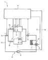
- FIG. 1 The sole FIGURE of the drawing shows a fuel cell system 2 in a highly simplified and schematic representation with a first fuel cell module 4 and a second fuel cell module 6, which together form a fuel cell battery.
- Both fuel cell modules 4, 6 are electrically connected to a load, not shown, for example, a motor of a vehicle, which supply the two fuel cell modules 4, 6 with their power with drive energy, this supply is controlled by a processing means 8.
- the fuel cell system 2 also includes a cooling device 10 with a radiator 12 and a coolant pump 14, which is provided for pumping coolant through a coolant circuit 16.
- a coolant flow in the coolant circuit 16 is split in parallel to the two fuel cell modules 4, 6 and flows through them in two separate coolant streams, wherein the individual coolant flows through the fuel cell modules 4, 6 by a respective valve 18, 20 can be switched on or off separately.
- the coolant circuit 16 also includes a mixing valve 22, by which the proportion of the coolant flowing through the radiator 12 can be adjusted from the total coolant flow in the coolant circuit.
- the mixing valve 22 is controlled by the processing means 8, which sets the mixing valve 22 as a control variable in a control loop a set value 24 for the position of the mixing valve 22.
- the coolant pump 14 is also controlled by the process means, which prescribes a desired value 26 for the speed of the coolant pump 14 as a manipulated variable in a further control loop.
- the two valves 18, 20 are driven by the processing means 8, that their position "on” or "to” pretends. Intermediate positions are not provided.
- a temperature sensor 28, 30, which are signal-connected to the processing means 8, so that the temperatures measured by temperature sensors 28, 30 can be monitored by the processing means 8.
- two further temperature sensors 32, 34 are outside the fuel cell modules 4, 6 arranged in the coolant circuit 16, wherein the temperature sensor 32, the input temperature T E of the coolant at the input of the fuel cell battery measures and the temperature sensor 34, the output temperature T A at the output of the fuel cell battery.
- the current through the two fuel cell modules 4, 6 is also individually monitored by the processing means 8.
- the first fuel cell module 4 is in operation, while the second fuel cell module 6 is switched off and generates no current.
- the valve 18 is open, the valve 20 is closed and the electrical load is only connected to the first fuel cell module 4.
- the thermal energy or heat generated in the fuel cell module 4 is for the most part to the coolant that flows through the fuel cell module 4, discharged and emitted to another, smaller part of the fuel cell module 4 to the outside.
- the heated coolant is passed partially through the radiator 12 and partially through a bypass 40 on the radiator 12, corresponding to the position of the mixing valve 22.
- the strength of the coolant flow in the coolant circuit 16 and thus by the fuel cell module 4 is determined by the speed of the coolant pump 14.
- the outlet temperature T A of the coolant at the temperature sensor 34 is constantly monitored by the processing means 8 and used as a control variable for a temperature control.
- the setpoint value 24 of the position of the mixing valve 22 is used, and the default value for the control is a temperature of 75 ° C as the starting temperature T A. If this rises above 75 ° C., then the mixing valve 22 is opened further towards the cooler 12 and the proportion of coolant flowing through the cooler 12 is thereby increased, as a result of which the inlet temperature T E drops and thus also - with stable operating conditions - the outlet temperature T A after a while.
- the temperature control the cooling capacity of the coolant flow in the fuel cell module 4 is controlled indirectly.
- the size of the current generated by the fuel cell module 4 changes accordingly.
- the generation of heat in the fuel cell module 4 is influenced, wherein the heat generated increases with increasing current.
- the fuel cell module 4 is warmer in its interior, it is given more heat to the coolant flow, the cooling power increases and with it the output temperature T A.
- the mixing valve 22 is opened further in the direction of the radiator 12, more coolant flows through the radiator 12, where more heat is released from the coolant, so that the inlet temperature T E, for example, can be kept constant at 65 ° C or at a more extensive Control the input temperature T E to compensate for the larger amount of heat generated in the fuel cell module 4 decreases to a lower value.
- the cooling capacity of the coolant flow in the fuel cell module 4 is controlled by the process means 8 by setting the target value 26 of the rotational speed of the coolant pump 14.
- the control takes place as a function of the current I 1 through the fuel cell module 4, so that according to a mathematical conversion or a characteristic curve, the rotational speed at high current I 1 is large and smaller at smaller current I 1 . Due to the higher speed of the coolant pump 14, the coolant flows faster through the fuel cell module 4, the coolant flow is thus greater, which is due to a higher power production higher heat generation in the fuel cell module 4 with a higher cooling capacity.
- the positive control value change doubles, so that the mixing valve 22 is opened twice as far in addition to the cooler 12. If the current gradient is constant, for example because the current I 1 continuously increases linearly, the disturbance that is applied to the control is constant. If the current gradient disappears, the connection of the disturbance variable to the control is also ended.
- the mixing valve 22 thus opens substantially at the same time as the occurrence of an eg positive current gradient in the direction of the cooler 12, so that the input temperature T E decreases within a short time.
- heating of the fuel cell module 4 is counteracted very quickly without having to wait for a response of the starting temperature T A as a controlled variable to the positive current gradient.
- a negative current gradient ie with a reduction of the load on the fuel cell module 4, it is possible to proceed analogously taking into account the other sign.
- the process means 8 If the temperature T 1 in the fuel cell module 4 increases for some reason, for example due to a very high positive current gradient, above a predetermined value, e.g. B. 85 ° C, it is detected by the process means 8 that the temperature T 1 continuously monitored. It is then generated by the processing means 8, a control deviation, which is connected as a disturbance variable to the manipulated variable, ie the set value 24 of the position of the mixing valve 22. This connection is in addition to the due to the current gradient connection. The mixing valve 22 is thus opened even further than by the temperature control and a evt1. intrusion is predetermined by the current gradient. Analog and reversed sign of the disturbance can be moved at a temperature T 1 in the fuel cell module 4 below a predetermined value.
- a predetermined value e.g. B. 85 ° C
- the rotational speed of the coolant pump 14 can be regulated.
- the temperature difference between the output temperature T A and the input temperature T E can be used.
- a temperature range of the controlled variable is provided within which the controls are suspended.
- the range can range from 9 ° C to 12 ° C, or even narrower from 10 ° C to 11 ° C. Only when the temperature difference rises above a predetermined value, for example above 11 ° C, the control can begin with a corresponding control of the speed of the coolant pump 14.
- a sharp value for the desired temperature difference for example, 10.5 ° C, and to superimpose the control by a continuous correction control.
- different limit values can be predetermined.
- This control superimposes the control of the speed on the basis of the current I 1 and is provided as a correction control that regulates the temperature difference, for example in a predetermined range. If the temperature difference exceeds the setpoint value or the upper limit value of the regulation-free range, then the rotational speed of the coolant pump 14 is increased. Analogously, the speed is reduced when the temperature difference falls below the setpoint or below the lower limit of the control-free range.
- the second valve 20 When, connecting the second fuel cell module 6 to the first fuel cell module 4, the second valve 20 is opened and thus generates an additional coolant flow, which is passed through the second fuel cell module 6.
- the entire coolant flow from the coolant circuit 16 is now distributed to both fuel cell modules 4, 6, so that the fuel cell module 4 still carrying the full current is cooled less.
- the control of the rotational speed can additionally take place as a function of the number of the cooled fuel cell modules 4, 6.
- the second fuel cell module 6 takes over part of the electrical load so that the current through the first fuel cell module 4 decreases.
- the electrical load is then distributed, for example, uniformly to the two fuel cell modules 4, 6. It is now possible to carry out the control of the rotational speed of the coolant pump 14 as a function of the battery current, that is to say the total current through all the fuel cell modules 4, 6.
- the rotational speed of the coolant pump 14 is controlled as a function of the maximum current I 1 , I 2 through the fuel cell modules 4, 6. If, for example, the first fuel cell module 4 carries the larger electrical load, the rotational speed is dependent on its current I 1 and independent of the current I 2 through the second fuel cell module 6. The other and less current-carrying fuel cell module 6 is hereby cooled more than necessary, this is however tolerable.
- the speed of the coolant pump 14 is already a period before closing the valve 18, so before stopping the flow of coolant through the fuel cell module 4, the process means 8 in terms of switching off the Fuel cell module 4 reduced. This reduction is expediently carried out only after the period of time which is provided for aftercooling and which starts after switching off the fuel cell module 4 from the electrical load. Only after the speed reduction of the coolant pump 14 has been completed, the valve 18 is closed and the coolant flow is conducted completely through the second fuel cell module 6.
Landscapes
- Engineering & Computer Science (AREA)
- Sustainable Energy (AREA)
- Life Sciences & Earth Sciences (AREA)
- Manufacturing & Machinery (AREA)
- Sustainable Development (AREA)
- Chemical & Material Sciences (AREA)
- Chemical Kinetics & Catalysis (AREA)
- Electrochemistry (AREA)
- General Chemical & Material Sciences (AREA)
- General Physics & Mathematics (AREA)
- Physics & Mathematics (AREA)
- Automation & Control Theory (AREA)
- Fuel Cell (AREA)
Description
- Die Erfindung betrifft ein Verfahren zur Temperaturregelung in einer Brennstoffzellenanlage mit zumindest einem Brennstoffzellenmodul und einer Kühlvorrichtung zum Kühlen des Brennstoffzellenmoduls, bei dem Kühlmittel durch das Brennstoffzellenmodul geführt wird und ein Prozessmittel eine Temperatur des Kühlmittels am Ausgang des Brennstoffzellenmoduls regelt. Außerdem betrifft die Erfindung eine Brennstoffzellenanlage mit zumindest einem Brennstoffzellenmodul, einer Kühlvorrichtung zum Führen von Kühlmittel durch das Brennstoffzellenmodul und mit einem Prozessmittel, das dazu vorgesehen ist, eine Temperatur des Kühlmittels zu regeln.
- In einer Brennstoffzelle reagieren Wasserstoff (H2) und Sauerstoff (O2) an einem Elektrolyten unter Abgabe von Wärme und elektrischer Energie zu Produktwasser. Zum Erzeugen einer für große Stromverbraucher geeigneten Leistung werden eine Vielzahl von Brennstoffzellen in Reihe geschaltet und zu einem Brennstoffzellenmodul zusammengefasst, zum Beispiel in Form eines Stapels aus einer Vielzahl von plattenförmigen Brennstoffzellen.
- Die bei dem elektrochemischen Prozess erzeugte Wärme wird zum größten Teil an ein Kühlmittel abgegeben, beispielsweise Wasser, das in einem Kühlmittelstrom die Brennstoffzellen eines Brennstoffzellenmoduls durch- oder umströmt. Die Menge der vom Brennstoffzellenmodul erzeugten thermischen Energie bzw. wärme ist abhängig von der Menge der im Brennstoffzellenmodul erzeugten elektrischen Energie, die wiederum abhängt von der Größe der elektrischen Last, die an das Brennstoffzellenmodul angeschaltet ist. Je größer die elektrische Last ist, desto mehr Wärme wird erzeugt und desto größer muss eine Kühlleistung des Kühlmittelstroms sein, um die Brennstoffzellen im Brennstoffzellenmodul innerhalb eines vorgegebenen Temperaturbereichs zu halten.
- Zur Kühlung eines Brennstoffzellenmoduls ist es bekannt, die Temperatur des Kühlmittels an einem Kühlmittelausgang des Brennstoffzellenmoduls zu messen und zu regeln, wobei eine Stellgröße der Regelung beispielsweise eine Stellung eines Mischventils an einem Kühler ist.
- Die Verwendung eines Stromflusses durch das Brennstoffzellenmodul zur Korrektur der Temperaturregelung ist beispielsweise aus der
US 3,595,699 , derUS 6,186,254 und derUS 2006/172164 A1 bekannt. - Es ist eine Aufgabe der vorliegenden Erfindung, ein Verfahren zur Temperaturregelung in einer Brennstoffzellenanlage und eine Brennstoffzellenanlage anzugeben, bei denen eine Temperatur der Brennstoffzellen des Brennstoffzellenmoduls sehr gleichmäßig gehalten werden kann.
- Die auf das Verfahren gerichtete Aufgabe wird durch ein Verfahren der eingangs genannten Art gelöst, bei dem erfindungsgemäß die Kühlmitteltemperatur innerhalb des Brennstoffzellenmoduls gemessen wird und eine aus dem Messwert abgeleitete Störgröße und eine Änderung des elektrischen Stroms durch das Brennstoffzellenmodul als weitere Störgröße auf die Regelung aufgeschaltet werden. Bei einer Leistungserhöhung des Brennstoffzellenmoduls kann einer Temperaturerhöhung in den Brennstoffzellen frühzeitig entgegen gewirkt werden und die Temperatur kann zuverlässig in einem erlaubten Temperaturbereich gehalten werden.
- Die Erfindung geht hierbei von der Überlegung aus, dass bei einem Lastanstieg des Brennstoffzellenmoduls ein Temperaturanstieg in den Brennstoffzellen bei einer Regelung der Ausgangstemperatur erst relativ spät im Regelkreis erfasst wird und die Kühlleistung des Kühlmittelstroms im Brennstoffzellenmodul daher erst relativ spät erhöht wird. Hierdurch kommt es - je nach Laständerungen - zu positiven oder negativen Temperaturspitzen, die außerhalb eines für das Brennstoffzellenmodul gewünschten Temperaturbereichs liegen können.
- Um die Reaktionsgeschwindigkeit des Regelkreises zu erhöhen, kann die Regelung mit einer Steuerung kombiniert werden, beispielsweise indem die Kühlleistung in Abhängigkeit von der Last am Brennstoffzellenmodul bzw. vom Strom durch das Brennstoffzellenmodul gesteuert wird. Es ergibt sich hierdurch eine Kombination aus Regelung nach der Temperatur und Steuerung nach dem Strom des Brennstoffzellenmoduls. Auf diese Weise kann einer Erhöhung der Kühlmitteltemperatur bei einer Leistungssteigerung des Brennstoffzellenmoduls schnell entgegengewirkt werden.
- Eine noch schnellere Reaktion gegen ein unerwünschtes Aufheizen von Kühlmittel im Brennstoffzellenmodul kann durch die Korrektur der Regelung anhand der Änderung des elektrischen Stroms durch das Brennstoffzellenmodul - im Folgenden als Stromgradient bezeichnet - erreicht werden. Bei einem kleinen Stromgradienten, also einer langsamen Änderung des elektrischen Stroms, wird die Regelung demzufolge leicht korrigiert und bei einer schnelleren Änderung des elektrischen Stroms stärker korrigiert. Der Stromgradient kann hierbei - beispielsweise anhand eines Kennfelds oder einer mathematischen Funktion - als Störgröße auf die Regelung aufgeschaltet und diese hierdurch korrigiert werden. Es kann eine vorausschauende Anpassung der Kühlleistung erreicht werden, wodurch trotz einer gewissen Zeitdauer, die das Kühlmittel zum Durchströmen des Brennstoffzellenmoduls braucht, eine schnelle Reaktion der Kühlleistung an die Wärmeerzeugung ermöglicht wird.
- Die Erfindung ist besonders vorteilhaft anwendbar bei einem Brennstoffzellenblock, bei dem flache, vorzugsweise rechteckige Brennstoffzellen zu einem Block aufeinander gestapelt sind. Ein solcher Block kann zusammen mit Medienkanälen, Abschlussplatten, Befeuchtungszellen und weiteren Elementen das Brennstoffzellenmodul bilden. Als Kühlmittel kann eine Flüssigkeit vorgesehen sein, die vorzugsweise überwiegend aus Wasser besteht.
- Die geregelte Temperatur ist eine Kühlmitteltemperatur am Ausgang des Brennstoffzellenmoduls. Auf diese weise kann die Kühlleistung des Kühlmittelstroms im Brennstoffzellenmodul besonders einfach geregelt werden.
- Vorteilhafterweise umfasst die Kühlvorrichtung einen Kühlmittelkreislauf mit einem Kühler und einem Mischventil, mit dem ein Verhältnis zwischen durch den Kühler und am Kühler vorbei geführtem Kühlmittel eingestellt wird, wobei die Stellung des Mischventils eine Stellgröße der Regelung bildet. Hierdurch kann die Einstellung der Eingangstemperatur des Kühlmittels an einem Eingang des Brennstoffzellenmoduls und dadurch die Kühlleistung einfach erfolgen. Wird mehr Kühlmittel über den Kühler geführt, so sinkt die Eingangstemperatur des Kühlmittels und die Kühlleistung steigt - bei gleich bleibender Wärmeerzeugung im Brennstoffzellenmodul - an.
- Eine zuverlässige und einfache Korrektur der Regelung kann erreicht werden, wenn die Änderung des elektrischen Stroms durch das Brennstoffzellenmodul als Störgröße auf eine Stellgröße der Regelung aufgeschaltet wird, insbesondere linear. Die Stellgröße, beispielsweise eine Ventilstellung des Mischventils, kann schnell und steuerungstechnisch einfach entsprechend des Stromgradienten korrigierend eingestellt werden, wobei bei ansteigendem Stromgradienten die korrigierend Verstellung der Stellgröße insbesondere entsprechend linear ansteigt. Bei gleich bleibendem Stromgradienten also gleichmäßig ansteigendem Strom durch das Brennstoffzellenmodul, kann die korrigierende Verstellung der Stellgröße konstant bleiben und bei konstantem Strom, also verschwindendem Stromgradienten, wieder auf Null zurückgenommen werden. Analog kann bei negativem Stromgradienten verfahren werden.
- Um ein Aufschwingen des Regelkreises zu vermeiden erfolgt die Korrektur der Regelung zweckmäßigerweise nur innerhalb eines Stellbereichs einer Stellgröße der Regelung, der kleiner ist als der gesamte für eine reguläre Regelung zur verfügung stehende Stellbereich der Stellgröße.
- Die Kühlmitteltemperatur wird innerhalb des Brennstoffzellenmoduls gemessen und eine aus dem Messwert abgeleitete Störgröße wird auf die Regelung aufgeschaltet. Hierfür umfasst die Brennstoffzellenanlage vorteilhafterweise zumindest einen Sensor im Brennstoffzellenmodul zur Erfassung der Temperatur innerhalb des Brennstoffzellenmoduls. Verlässt die Temperatur beispielsweise einen vorgegebenen Temperaturbereich, so wird eine zusätzliche Regelabweichung generiert, die zusätzlich zur Störgröße aus dem Stromgradienten auf die Regelung aufgeschaltet wird. Diese Störgrößenaufschaltung kann solange bestehen bleiben, wie die gemessene Temperatur innerhalb des Brennstoffzellenmoduls außerhalb des Temperaturbereichs liegt.
- Zweckmäßigerweise ist die Störgröße eine progressive Störgröße, sodass z.B. bei einem Überschreiten der Temperatur über den oberen Grenzwert des Temperaturbereichs zunächst eine sanfte Regelabweichung erfolgt, die bei weiterem Ansteigen der Temperatur progressiv ansteigt.
- Vorteilhafterweise umfasst die Kühlvorrichtung einen Mengengeber zum Einstellen der Stärke des Kühlmittelstroms durch das Brennstoffzellenmodul. Der Mengengeber kann ein Ventil sein oder eine Kühlmittelpumpe, deren Pumpleistung einstellbar ist. Auf diese Weise kann die Temperatur durch ein Einstellen der Pumpleistung eingestellt werden. Zweckmäßigerweise wird die Stärke des Kühlmittelstroms in Abhängigkeit von der Stärke des elektrischen Modulstroms durch das Brennstoffzellenmodul gesteuert, wodurch beispielsweise eine vorteilhafte Vorsteuerung erreicht werden kann.
- Umfasst die Brennstoffzellenanlage zumindest zwei von jeweils einem Kühlmittelstrom durchströmte Brennstoffzellenmodule, so wird die Stärke aller Kühlmittelströme vorteilhafterweise in Abhängigkeit vom maximalen Strom der einzelnen Brennstoffzellenmodule gesteuert. Der momentan stärkste Modulstrom wird somit zum steuern der Stärke aller Kühlmittelströme durch die Brennstoffzellenmodule herangezogen, auch durch solche, bei denen der Modulstrom, also der Strom durch das Brennstoffzellenmodul, geringer ist. Hierzu werden die Modulströme zweckmäßigerweise separat erfasst, so dass sie verglichen werden können. Da bei gleichem Batterienstrom, der die Summe aller Modulströme sein kann, der Kühlmittelstrom vorteilhafterweise umso größer ist, je mehr Brennstoffzellenmodule gekühlt werden, wird der maximale Strom zweckmäßigerweise gewichtet zur Steuerung verwendet. Die Wichtung kann sich aus der Anzahl der gekühlten Brennstoffzellenmodule ergeben.
- Soll ein Kühlmittelstrom durch ein Brennstoffzellenmodul beendet werden, während ein weiterer Kühlmittelstrom durch anderes Brennstoffzellenmodul weiter läuft, so ist es vorteilhaft, wenn die Stärke des weiteren Kühlmittelstroms unabhängig vom Modulstrom reduziert wird, bevor der andere Kühlmittelstrom beendet wird. Hierdurch kann vermieden werden, dass ein Druckstoß durch das den Modulstrom liefernde Brennstoffzellenmodul läuft, der zu einem Schaden an diesem Brennstoffzellenmodul führen kann.
- Eine weitere Erfindungsvariante sieht eine Regelung des Temperaturunterschieds des Kühlmittels vor und nach dem Brennstoffzellenmodul vor. Diese Regelung kann eine Regelung sein, die parallel zur Temperaturregelung geschieht und insbesondere korrigierend wirkt. Zweckmäßigerweise ist eine Pumpleistung einer Kühlmittelpumpe eine Stellgröße der Regelung. Durch diese Regelung kann der Temperaturunterschied beispielsweise auf einen vorgegebenen Temperaturbereich geregelt werden. Der Temperaturunterschied ist ein Maß für die Stärke des Kühlmittelstroms durch das Brennstoffzellenmodul bzw. des Gesamtkühlmittelstroms durch alle Brennstoffzellenmodule. Durch die Verwendung des Temperaturunterschieds als Regelgröße kann der Kühlmittelstrom in einem besonders vorteilhaften Bereich gehalten werden. Hierdurch kann das Brennstoffzellenmodul geschont und ein hoher Wirkungsgrad des Brennstoffzellenmoduls über einen langen Zeitraum erhalten bleiben.
- Vorteilhafterweise wird der Temperaturunterschied anhand einer Kennlinie über den Modulstrom geregelt. So kann der Soll-Temperaturunterschied bei niedrigen Strömen auf einen geringen Wert und bei hohen Strömen auf einen höheren Wert geregelt werden, z.B. auf 2°C bei 20% einer maximalen Modulleistung und auf 10° bei 100% der Modulleistung.
- Bei mehreren Brennstoffzellenmodulen kann der Temperaturunterschied zwischen einem Eingang zu allen Brennstoffzellenmodulen und einem Ausgang aus allen Brennstoffzellenmodulen verwendet werden. Zweckmäßigerweise fließt in die Regelung ein, wie viele Brennstoffzellemodule durch die Kühlvorrichtung momentan gekühlt werden. Dies kann durch unterschiedliche Kennlinien - je nach Anzahl der Brennstoffzellenmodule, die in Betrieb sind - geschehen.
- Zweckmäßigerweise sind die Kennlinien ab einer Leistung von 50% der maximalen Leistung der Brennstoffzellenanlage, insbesondere ab 70% von deren Leistung, konstant.
- Die auf die Brennstoffzellenanlage gerichtete Aufgabe wird durch eine Brennstoffzellenanlage der eingangs genannten Art gelöst, bei der das Prozessmittel erfindungsgemäß dazu vorgesehen ist, die Kühlmitteltemperatur innerhalb des Brennstoffzellenmoduls zu erfassen und eine aus dem Messwert abgeleitete Störgröße und eine Änderung des elektrischen Stroms durch das Brennstoffzellenmodul als weitere Störgröße auf die Regelung aufzuschalten. Auf durch Laständerungen bedingte Temperaturschwankungen innerhalb des Brennstoffzellenmoduls kann schnell reagiert werden, sodass diese Schwankungen gering gehalten werden können. Das Prozessmittel ist vorteilhafterweise dazu vorgesehen, die oben beschriebenen Verfahrensschritte zu steuern bzw. zu regeln.
- Die Erfindung wird anhand eines Ausführungsbeispiels näher erläutert, das in der Zeichnung dargestellt ist.
- Die einzige Figur der Zeichnung zeigt eine Brennstoffzellenanlage 2 in einer stark vereinfachten und schematisierten Darstellung mit einem ersten Brennstoffzellenmodul 4 und einem zweiten Brennstoffzellenmodul 6, die zusammen eine Brennstoffzellenbatterie bilden. Beide Brennstoffzellenmodule 4, 6 sind elektrisch mit einer nicht dargestellten Last verbunden, beispielsweise einem Motor eines Fahrzeugs, den die beiden Brennstoffzellenmodule 4, 6 mit ihrem Strom mit Antriebsenergie versorgen, wobei diese Versorgung durch ein Prozessmittel 8 gesteuert ist.
- Die Brennstoffzellenanlage 2 umfasst außerdem eine Kühlvorrichtung 10 mit einem Kühler 12 und einer Kühlmittelpumpe 14, die zum Pumpen von Kühlmittel durch einen Kühlmittelkreislauf 16 vorgesehen ist. Ein Kühlmittelstrom im Kühlmittelkreislauf 16 ist parallel auf die beiden Brennstoffzellenmodule 4, 6 aufgeteilt und durchströmt diese in zwei separaten Kühlmittelströmen, wobei die einzelnen Kühlmittelströme durch die Brennstoffzellenmodule 4, 6 durch jeweils ein Ventil 18, 20 separat an- oder abgeschaltet werden können. Der Kühlmittelkreislauf 16 umfasst außerdem ein Mischventil 22, durch das der Anteil des durch den Kühler 12 strömenden Kühlmittels vom gesamten Kühlmittelstrom im Kühlmittelkreislauf eingestellt werden kann.
- Das Mischventil 22 wird vom Prozessmittel 8 gesteuert, das dem Mischventil 22 als Stellgröße in einem Regelkreis einen Sollwert 24 für die Stellung des Mischventils 22 vorgibt. Auch die Kühlmittelpumpe 14 wird vom Prozessmittel gesteuert, das der Kühlmittelpumpe 14 einen Sollwert 26 für dessen Drehzahl als Stellgröße in einem weiteren Regelkreis vorgibt. Des Weiteren werden die beiden Ventile 18, 20 vom Prozessmittel 8 angesteuert, dass deren Stellung "auf" oder "zu" vorgibt. Zwischenstellungen sind nicht vorgesehen.
- Innerhalb der Brennstoffzellenmodule 4, 6 ist jeweils ein Temperatursensor 28, 30 vorhanden, die mit dem Prozessmittel 8 signaltechnisch verbunden sind, sodass die von Temperatursensoren 28, 30 gemessenen Temperaturen vom Prozessmittel 8 überwacht werden können. Außerdem sind zwei weitere Temperatursensoren 32, 34 außerhalb der Brennstoffzellenmodule 4, 6 im Kühlmittelkreislauf 16 angeordnet, wobei der Temperatursensor 32 die Eingangstemperatur TE des Kühlmittels am Eingang der Brennstoffzellenbatterie misst und der Temperatursensor 34 die Ausgangstemperatur TA am Ausgang der Brennstoffzellenbatterie. Mit entsprechenden Stromsensoren 36, 38 wird außerdem vom Prozessmittel 8 der Strom durch die beiden Brennstoffzellenmodule 4, 6 jeweils einzeln überwacht.
- Während des Betriebs sei zunächst nur das erste Brennstoffzellenmodul 4 in Betrieb, während das zweite Brennstoffzellenmodul 6 abgeschaltet ist und keinen Strom erzeugt. Das Ventil 18 ist geöffnet, das Ventil 20 ist geschlossen und die elektrische Last ist nur an das erste Brennstoffzellenmodul 4 angeschaltet. Die im Brennstoffzellenmodul 4 erzeugte thermische Energie bzw. Wärme wird zum größten Teil an das Kühlmittel, dass das Brennstoffzellenmodul 4 durchströmt, abgegeben und zu einem anderen, kleineren Teil vom Brennstoffzellenmodul 4 nach außen abgestrahlt. Das erwärmte Kühlmittel wird teilweise durch den Kühler 12 und teilweise durch einen Bypass 40 am Kühler 12 vorbeigeführt, entsprechend der Stellung des Mischventils 22. Die Stärke des Kühlmittelstroms im Kühlmittelkreislauf 16 und damit durch das Brennstoffzellenmodul 4 wird durch die Drehzahl der Kühlmittelpumpe 14 vorgegeben.
- Die Ausgangstemperatur TA des Kühlmittels am Temperatursensor 34 wird ständig vom Prozessmittel 8 überwacht und als Regelgröße für eine Temperaturregelung verwendet. Als Stellwert in dieser Regelung wird der Sollwert 24 der Stellung des Mischventils 22 verwendet, und der Vorgabewert für die Regelung ist eine Temperatur von 75°C als Ausgangstemperatur TA. Steigt diese über 75°C an, so wird das Mischventil 22 zum Kühler 12 hin weiter geöffnet und damit wird der Anteil des den Kühler 12 durchströmenden Kühlmittels erhöht, wodurch die Eingangstemperatur TE sinkt und damit auch - bei stabilen Betriebsverhältnissen - die Ausgangstemperatur TA nach einer Weile. Durch die Temperaturregelung wird die Kühlleistung des Kühlmittelstroms im Brennstoffzellenmodul 4 indirekt geregelt.
- Tritt während des Betriebs eine Änderung der elektrischen Last auf, so ändert sich die Größe des vom Brennstoffzellenmodul 4 erzeugten Stroms entsprechend. Hierdurch wird auch die Erzeugung der Wärme im Brennstoffzellenmodul 4 beeinflusst, wobei die erzeugte Wärme mit steigendem Strom ansteigt. Das Brennstoffzellenmodul 4 wird in seinem Inneren wärmer, es wird mehr Wärme an den Kühlmittelstrom abgegeben, die Kühlleistung steigt und mit ihr die Ausgangstemperatur TA. Infolge der Regelung wird das Mischventil 22 in Richtung zum Kühler 12 weiter geöffnet, es strömt mehr Kühlmittel durch den Kühler 12, dort wird mehr Wärme vom Kühlmittel abgegeben, sodass die Eingangstemperatur TE beispielsweise konstant auf 65°C gehalten werden kann oder bei einer weitergehenden Regelung die Eingangstemperatur TE zum Kompensieren der größeren erzeugten Wärmemenge im Brennstoffzellenmodul 4 auf einen niedrigeren Wert absinkt.
- Zusätzlich zu dieser Regelung wird die Kühlleistung des Kühlmittelstroms im Brennstoffzellenmodul 4 vom Prozessmittel 8 durch ein Einstellen des Sollwerts 26 der Drehzahl der Kühlmittelpumpe 14 gesteuert. Die Steuerung geschieht in Abhängigkeit vom Strom I1 durch das Brennstoffzellenmodul 4, sodass entsprechend einer mathematischen Umrechnung oder einer Kennlinie die Drehzahl bei großem Strom I1 groß ist und bei kleinerem Strom I1 kleiner ist. Durch die höhere Drehzahl der Kühlmittelpumpe 14 strömt das Kühlmittel schneller durch das Brennstoffzellenmodul 4, der Kühlmittelstrom ist also größer, wodurch einer durch eine höhere Stromproduktion bedingte höhere Wärmeerzeugung im Brennstoffzellenmodul 4 mit einer höheren Kühlleistung Rechnung getragen wird.
- Bei einer großen Leistungserhöhung des Brennstoffzellenmoduls 4 kann es aufgrund der schnell ansteigenden Menge an erzeugter Wärmeenergie trotz der Steuerung nach dem Strom zu einem erheblichen Temperaturanstieg innerhalb des Brennstoffzellenmoduls 4 kommen. Um diesem Temperaturanstieg entgegen zu wirken, wird die Änderung des elektrischen Stroms durch das Brennstoffzellenmodul 4, also der Stromgradient, als Korrekturgröße für die beschriebene Regelung verwendet. Hierzu wird der Strom I1 durch das Brennstoffzellenmodul 4 kontinuierlich vom Prozessmittel 8 überwacht und ein Stromgradient wird erkannt. Bei positivem Stromgradienten wird dieser - vom Prozessmittel 8 umgewandelt in eine Stellwertänderung - linear auf den Sollwert 24 der Stellung des Mischventils 22 aufgeschaltet. Verdoppelt sich beispielsweise der positive Stromgradient, so verdoppelt sich auch die positive Stellwertänderung, das Mischventil 22 wird also doppelt so weit zusätzlich zum Kühler 12 hin geöffnet. Ist der Stromgradient konstant, beispielsweise weil der Strom I1 kontinuierlich linear ansteigt, ist auch die Störgröße, die auf die Regelung aufgeschaltet wird, konstant. Verschwindet der Stromgradient so wird auch das Aufschalten der Störgröße auf die Regelung beendet.
- Das Mischventil 22 öffnet somit im Wesentlichen zeitgleich mit dem Auftreten eines z.B. positiven Stromgradienten in Richtung zum Kühler 12 hin, sodass die Eingangstemperatur TE innerhalb von kurzer Zeit sinkt. Hierdurch wird einer Erwärmung des Brennstoffzellenmoduls 4 sehr zügig entgegengewirkt, ohne auf eine Reaktion der Ausgangstemperatur TA als Regelgröße auf den positiven Stromgradienten warten zu müssen. Bei negativem Stromgradienten, also bei einer Verringerung der Last am Brennstoffzellenmodul 4, kann unter Berücksichtigung des anderen Vorzeichens analog verfahren werden.
- Steigt die Temperatur T1 im Brennstoffzellenmodul 4 aus irgendeinem Grund, beispielsweise durch einen sehr hohen positiven Stromgradienten, über einen vorbestimmten Wert, z. B. 85°C, so wird dies vom Prozessmittel 8 erkannt, dass die Temperatur T1 kontinuierlich überwacht. Es wird dann vom Prozessmittel 8 eine Regelabweichung generiert, die als Störgröße auf die Stellgröße, also den Sollwert 24 der Stellung des Mischventils 22, aufgeschaltet wird. Diese Aufschaltung ist zusätzlich zu der durch den Stromgradienten bedingten Aufschaltung. Das Mischventil 22 wird also noch weiter geöffnet als durch die Temperaturregelung und einer evt1. Aufschaltung durch den Stromgradient vorgegeben ist. Analog und mit umgekehrtem Vorzeichen der Störgröße kann bei einer Temperatur T1 im Brennstoffzellenmodul 4 unter einen vorbestimmten Wert verfahren werden.
- Zusätzlich zu der Steuerung der Drehzahl der Kühlmittelpumpe 14 kann die Drehzahl geregelt werden. Als Regelgröße kann die Temperaturdifferenz zwischen der Ausgangstemperatur TA und der Eingangstemperatur TE verwendet werden. Hierbei ist es allerdings vorteilhaft, wenn ein Temperaturbereich der Regelgröße vorgesehen ist, innerhalb dessen die Regelungen ausgesetzt wird. Der Bereich kann beispielsweise von 9°C bis 12°C gehen, oder sogar noch enger von 10°C bis 11°C gehen. Erst wenn die Temperaturdifferenz über einen vorbestimmten Wert steigt, beispielsweise über 11°C, so kann die Regelung einsetzen mit einer entsprechenden Regelung der Drehzahl der Kühlmittelpumpe 14. Selbstverständlich ist es auch möglich, einen scharfen Wert für die anstrebte Temperaturdifferenz, beispielsweise 10,5°C, vorzugeben und die Steuerung durch eine kontinuierliche Korrekturregelung zu überlagern. Je nach Anzahl der in Betrieb befindlichen Brennstoffzellenmodule 2, 4 können unterschiedliche Grenzwerte vorgegeben sein.
- Diese Regelung überlagert die Steuerung der Drehzahl anhand des Strom I1 und ist als Korrekturregelung vorgesehen, die die Temperaturdifferenz regelt, z.B. in einem vorgegebenen Bereich. Überschreitet die Temperaturdifferenz den Sollwert oder den oberen Grenzwert des regelungsfreien Bereichs, so wird die Drehzahl der Kühlmittelpumpe 14 erhöht. Analog hierzu wird die Drehzahl bei einem Unterschreiten der Temperaturdifferenz unter den Sollwert bzw. unter die untere Grenze des regelungsfreien Bereichs verringert.
- Bei einem Betrieb mit beiden Brennstoffzellenmodulen 4, 6 kann die beschriebene Steuerung und die Regelungen gleicherweise für beide Brennstoffzellenmodule 4, 6 erfolgen.
- Bei einem, Zuschalten des zweiten Brennstoffzellenmoduls 6 zum ersten Brennstoffzellenmodul 4, so wird das zweite Ventil 20 geöffnet und somit ein zusätzlicher Kühlmittelstrom erzeugt, der durch das zweite Brennstoffzellenmodul 6 hindurchgeführt ist. Bei gleich bleibender Drehzahl der Kühlmittelpumpe 14 verteilt sich nun der gesamte Kühlmittelstrom aus dem Kühlmittelkreislauf 16 auf beide Brennstoffzellenmodule 4, 6, sodass das noch den vollen Strom tragende Brennstoffzellenmodul 4 weniger gekühlt wird. Um einer hierdurch bedingten Temperaturerhöhung im Brennstoffzellenmodul 4 entgegenzuwirken, kann die Steuerung der Drehzahl zusätzlich in Abhängigkeit zu der Anzahl der gekühlten Brennstoffzellenmodule 4, 6 erfolgen.
- Nach etwa drei Minuten Startzeit übernimmt das zweite Brennstoffzellenmodul 6 einen Teil der elektrischen Last, sodass der Strom durch das erste Brennstoffzellenmodul 4 abnimmt. Die elektrische Last verteilt sich nun beispielsweise gleichmäßig auf die beiden Brennstoffzellenmodule 4, 6. Es besteht nun die Möglichkeit, die Steuerung der Drehzahl der Kühlmittelpumpe 14 in Abhängigkeit des Batteriestroms durchzuführen, also des Gesamtstroms durch alle Brennstoffzellenmodule 4, 6.
- Bei einer solchen Steuerung wird allerdings nicht berücksichtigt, dass die elektrische Leistung bzw. der Strom durch die Brennstoffzellenmodule 4, 6 auch ungleich verteilt sein kann, sodass eines der Brennstoffzellenmodule 4, 6 einer größeren Kühlleistung bedarf als das andere. Da beide Ventile 18, 20 offen sind, verteilt sich der gesamte Kühlmittelstrom des Kühlmittelkreislaufs 16 gleichmäßig auf die beiden Kühlmittelströme durch die Brennstoffzellenmodule 4, 6. Wird also beispielsweise die Verteilung der elektrischen Last durch das Prozessmittel 8 von einer gleichmäßigen Aufteilung auf die Brennstoffzellenmodule 4, 6 geändert in eine ungleichmäßige Aufteilung, so ändert sich die Stärke des Kühlmittelstroms durch dieses Brennstoffzellenmodul 4, 6 nicht obgleich dort mehr Wärme erzeugt wird. Da in dem anderen Brennstoffzellenmodul 4, 6 weniger Wärme erzeugt wird, wird die Änderung der Stromverteilung auch nicht oder nur ungenügend durch eine Änderung der Ausgangstemperatur TA oder eine Temperaturdifferenz zwischen der Ausgangstemperatur TA und der Eingangstemperatur TE erfasst.
- Um diesen Nachteil zu vermeiden, wird die Drehzahl der Kühlmittelpumpe 14 in Abhängigkeit maximalen Strom I1, I2 durch die Brennstoffzellenmodule 4, 6 gesteuert. Trägt beispielsweise das erste Brennstoffzellenmodul 4 die größere elektrische Last, so ist die Drehzahl abhängig von dessen Strom I1 und unabhängig vom Strom I2 durch das zweite Brennstoffzellenmodul 6. Das andere und weniger Strom tragende Brennstoffzellenmodul 6 wird hierdurch zwar stärker gekühlt als notwendig, dies ist jedoch tolerierbar.
- Allerdings kann eine derartige Steuerung der Drehzahl der Kühlmittelpumpe 14 bewirken, dass die Temperaturdifferenz durch den Zustrom von relativ kaltem Kühlmittel aus dem wenig Strom tragenden Brennstoffzellenmodul 4 zum Temperatursensor 34 stark absinkt. Eine Korrekturregelung der Drehzahl der Kühlmittelpumpe 14 wäre die Folge, sodass die Kühlleistung in beiden Brennstoffzellenmodulen 4, 6 absinkt und das den größten Strom tragende Brennstoffzellenmodul 4 weniger gekühlt werden würde. Um diesen Effekt zu vermeiden oder gering zu halten, fließt in die temperaturabhängige Korrekturregelung ein, wie viele Brennstoffzellenmodule 4, 6 durch die Kühlvorrichtung 10 momentan gekühlt werden. Bei mehreren Brennstoffzellenmodulen 4, 6 kann der regelungsfreie Bereich beispielsweise nach unten erweitert werden, sodass die Korrekturregelung auch bei einer geringen Temperaturdifferenz noch nicht einschreitet.
- Wird nun ein Brennstoffzellenmodul 4, 6 abgeschaltet, beispielsweise das erste Brennstoffzellenmodul 4, wohingegen das andere Brennstoffzellenmodul 6 weiter in Betrieb bleibt, wird nach dem Abschalten des elektrischen Stroms vom Brennstoffzellenmodul 4 dieses noch einen Zeitraum weiter gekühlt, um Restwärme aus dem Brennstoffzellenmodul 4 heraus zu tragen. Dann wird das entsprechende Ventil 18 geschlossen und der Kühlmittelstrom durch das Brennstoffzellenmodul 4 kommt zum Erliegen. Der volle Kühlmittelstrom wird durch das Strom tragende Brennstoffzellenmodul 6 hindurch getrieben. Einer Kühlung ist dieser Vorgang zwar nicht schädlich, jedoch ggf. einer Langlebigkeit und einem Wirkungsgrad des Brennstoffzellenmoduls 6. Ein solcher Druckstoß sollte somit vermieden werden. Da die Pumpleistung einer Gleichstrompumpe in der Regel nur langsam heruntergefahren werden kann, wird die Drehzahl der Kühlmittelpumpe 14 bereits einen Zeitraum vor dem Schließen des Ventils 18, also vor einem Stoppen des Kühlmittelstroms durch das Brennstoffzellenmodul 4, vom Prozessmittel 8 im Hinblick auf das Abschalten des Brennstoffzellenmoduls 4 reduziert. Dieses Reduzieren erfolgt zweckmäßigerweise erst nach dem Zeitabschnitt, der zum Nachkühlen vorgesehen ist und der nach dem Abschalten des Brennstoffzellenmoduls 4 von der elektrischen Last beginnt. Erst nach abgeschlossener Drehzahlreduzierung der Kühlmittelpumpe 14 wird das Ventil 18 geschlossen und der Kühlmittelstrom vollständig durch das zweite Brennstoffzellenmodul 6 geführt.
- Bei dem dargestellten Ausführungsbeispiel wurden die Verfahrensschritte nur für zwei Brennstoffzellenmodule 4, 6 erläutert. Selbstverständlich sind sie in gleicher Weise auch auf eine Brennstoffzellenanlage mit mehr Brennstoffzellenmodulen anwendbar, die einzeln, in einer Gruppe oder alle zusammen betrieben werden können.
Claims (10)
- Verfahren zur Temperaturregelung in einer Brennstoffzellenanlage (2) mit zumindest einem Brennstoffzellenmodul (4, 6) und einer Kühlvorrichtung (10) zum Kühlen des Brennstoffzellenmoduls (4, 6), bei dem Kühlmittel durch das Brennstoffzellenmodul (4, 6) geführt wird und ein Prozessmittel (8) eine Temperatur des Kühlmittels am Ausgang des Brennstoffzellenmoduls (4, 6) regelt,
dadurch gekennzeichnet, dass die Kühlmitteltemperatur innerhalb des Brennstoffzellenmoduls (4, 6) gemessen wird und eine aus dem Messwert abgeleitete Störgröße und eine Änderung des elektrischen Stroms (I1, I2) durch das Brennstoffzellenmodul (4, 6) als weitere Störgröße auf die Regelung aufgeschaltet werden. - Verfahren nach Anspruch 1,
dadurch gekennzeichnet, dass die Kühlvorrichtung (10) einen Kühlmittelkreislauf (16) mit einem Kühler (12) und einem Mischventil (22) aufweist, mit dem ein Verhältnis zwischen durch den Kühler (12) und am Kühler (12) vorbei geführtem Kühlmittel eingestellt wird, wobei die Stellung des Mischventils (22) eine Stellgröße der Regelung bildet. - Verfahren nach einem der vorhergehenden Ansprüche,
dadurch gekennzeichnet, dass die Änderung des elektrischen Stroms durch das Brennstoffzellenmodul (4, 6) als Störgröße auf eine Stellgröße der Regelung aufgeschaltet wird. , - Verfahren nach einem der vorhergehenden Ansprüche,
dadurch gekennzeichnet, dass die Temperatur durch ein Einstellen einer Pumpleistung einer Kühlmittelpumpe (14) eingestellt wird. - Verfahren nach einem der vorhergehenden Ansprüche,
dadurch gekennzeichnet, dass die Stärke des Kühlmittelstroms in Abhängigkeit von der Stärke des elektrischen Stroms (I1, I2) durch das Brennstoffzellenmodul (4, 6) gesteuert wird. - Verfahren nach einem der vorhergehenden Ansprüche,
dadurch gekennzeichnet, dass die Brennstoffzellenanlage (2) zumindest zwei von jeweils einem Kühlmittelstrom durchströmte Brennstoffzellenmodule (4, 6) aufweist und die Stärke aller Kühlmittelströme in Abhängigkeit vom maximalen Strom (I1, I2) der einzelnen Brennstoffzellenmodule (4, 6) gesteuert wird. - Verfahren nach Anspruch 6,
dadurch gekennzeichnet, dass die Stärke eines Kühlmittelstroms durch ein einen Modulstrom lieferndes Brennstoffzellenmodul (4, 6) unabhängig vom Modulstrom reduziert wird, bevor ein Kühlmittelstrom durch ein anderes Brennstoffzellenmodul (4, 6) gestoppt wird. - Verfahren nach einem der vorhergehenden Ansprüche,
gekennzeichnet durch eine Regelung des Temperaturunterschieds des Kühlmittels vor und nach dem Brennstoffzellenmodul (4, 6). - Verfahren nach Anspruch 8,
dadurch gekennzeichnet, dass in die Korrekturregelung einfließt, wie viele Brennstoffzellenmodule (4, 6) durch die Kühlvorrichtung (10) momentan gekühlt werden. - Brennstoffzellenanlage (2) mit zumindest einem Brennstoffzellenmodul (4, 6), einer Kühlvorrichtung (10) zum Führen von Kühlmittel durch das Brennstoffzellenmodul (4, 6) und mit einem Prozessmittel (10), das dazu vorgesehen ist, eine Temperatur des Kühlmittels am Ausgang des Brennstoffzellenmoduls (4, 6) zu regeln, ,
dadurch gekennzeichnet, dass das Prozessmittel (8) dazu vorgesehen ist, die Kühlmitteltemperatur innerhalb des Brennstoffzellenmoduls (4, 6) zu erfassen und eine aus dem Messwert abgeleitete störgröße und eine Änderung des elektrischen Stroms (I1, I2) durch das Brennstoffzellenmodul (4, 6) als weitere Störgröße auf die Regelung aufzuschalten.
Applications Claiming Priority (2)
| Application Number | Priority Date | Filing Date | Title |
|---|---|---|---|
| DE102008032156.7A DE102008032156B4 (de) | 2008-07-08 | 2008-07-08 | Verfahren zur Temperaturregelung in einer Brennstoffzellenanlage und Brennstoffzellenanlage |
| PCT/EP2009/058488 WO2010003912A1 (de) | 2008-07-08 | 2009-07-06 | Verfahren zur temperaturregelung in einer brennstoffzellenanlage und brennstoffzellenanlage |
Publications (2)
| Publication Number | Publication Date |
|---|---|
| EP2301100A1 EP2301100A1 (de) | 2011-03-30 |
| EP2301100B1 true EP2301100B1 (de) | 2012-03-07 |
Family
ID=41092148
Family Applications (1)
| Application Number | Title | Priority Date | Filing Date |
|---|---|---|---|
| EP09780174A Active EP2301100B1 (de) | 2008-07-08 | 2009-07-06 | Verfahren zur temperaturregelung in einer brennstoffzellenanlage und brennstoffzellenanlage |
Country Status (8)
| Country | Link |
|---|---|
| EP (1) | EP2301100B1 (de) |
| KR (1) | KR101319708B1 (de) |
| AT (1) | ATE548773T1 (de) |
| DE (1) | DE102008032156B4 (de) |
| ES (1) | ES2382158T3 (de) |
| IL (1) | IL210479A (de) |
| PT (1) | PT2301100E (de) |
| WO (1) | WO2010003912A1 (de) |
Families Citing this family (3)
| Publication number | Priority date | Publication date | Assignee | Title |
|---|---|---|---|---|
| DE102013001413B4 (de) | 2012-04-19 | 2024-01-18 | Audi Ag | Temperaturregelung für eine Brennstoffzelle |
| US11611089B2 (en) | 2021-08-05 | 2023-03-21 | Hydrogenics Corporation | Thermal management system and method of positioning and adjusting coolant flow for stationary vehicle fuel cell applications |
| CN114744258B (zh) * | 2022-05-26 | 2023-05-09 | 电子科技大学 | 一种基于扰动观察法的空冷型燃料电池温度控制方法 |
Family Cites Families (12)
| Publication number | Priority date | Publication date | Assignee | Title |
|---|---|---|---|---|
| US3539397A (en) * | 1967-05-23 | 1970-11-10 | United Aircraft Corp | Fuel cell with temperature control |
| US3595699A (en) * | 1969-02-13 | 1971-07-27 | Allis Chalmers Mfg Co | Fuel cell temperature control |
| AU5807296A (en) * | 1995-06-07 | 1996-12-30 | Ballard Power Systems Inc. | Temperature regulating system for a fuel cell powered vehicl e |
| US6186254B1 (en) * | 1996-05-29 | 2001-02-13 | Xcelliss Fuel Cell Engines Inc. | Temperature regulating system for a fuel cell powered vehicle |
| JP3769882B2 (ja) * | 1997-06-06 | 2006-04-26 | トヨタ自動車株式会社 | 燃料電池装置および燃料電池装置の温度調整方法 |
| DE19930876C2 (de) * | 1999-07-05 | 2003-04-17 | Siemens Ag | Brennstoffzellenanlage und Verfahren zur dynamischen Regelung der Temperatur und/oder der Zusammensetzung des Prozessgases der Brenstoffzellenanlage |
| JP4884604B2 (ja) * | 2001-07-04 | 2012-02-29 | 本田技研工業株式会社 | 燃料電池の冷却装置 |
| US7670700B2 (en) * | 2003-09-05 | 2010-03-02 | Denso Corporation | Fuel cell system, related method and current measuring device for fuel cell system |
| WO2005043661A1 (en) * | 2003-11-03 | 2005-05-12 | Greenlight Power Technologies, Inc. | Coolant flow control for a fuel cell testing station |
| JP2006049182A (ja) * | 2004-08-06 | 2006-02-16 | Nissan Motor Co Ltd | 燃料電池システム |
| JP4835001B2 (ja) * | 2005-02-03 | 2011-12-14 | 株式会社デンソー | 燃料電池システム |
| JP2007317559A (ja) * | 2006-05-26 | 2007-12-06 | Kawamura Electric Inc | 燃料電池の温度制御装置 |
-
2008
- 2008-07-08 DE DE102008032156.7A patent/DE102008032156B4/de not_active Expired - Fee Related
-
2009
- 2009-07-06 KR KR1020117001712A patent/KR101319708B1/ko active Active
- 2009-07-06 EP EP09780174A patent/EP2301100B1/de active Active
- 2009-07-06 AT AT09780174T patent/ATE548773T1/de active
- 2009-07-06 WO PCT/EP2009/058488 patent/WO2010003912A1/de not_active Ceased
- 2009-07-06 PT PT09780174T patent/PT2301100E/pt unknown
- 2009-07-06 ES ES09780174T patent/ES2382158T3/es active Active
-
2011
- 2011-01-06 IL IL210479A patent/IL210479A/en active IP Right Grant
Also Published As
| Publication number | Publication date |
|---|---|
| PT2301100E (pt) | 2012-05-24 |
| KR101319708B1 (ko) | 2013-10-17 |
| ES2382158T3 (es) | 2012-06-05 |
| ATE548773T1 (de) | 2012-03-15 |
| WO2010003912A1 (de) | 2010-01-14 |
| KR20110022075A (ko) | 2011-03-04 |
| DE102008032156B4 (de) | 2014-02-13 |
| DE102008032156A1 (de) | 2010-01-14 |
| EP2301100A1 (de) | 2011-03-30 |
| IL210479A0 (en) | 2011-03-31 |
| IL210479A (en) | 2015-09-24 |
Similar Documents
| Publication | Publication Date | Title |
|---|---|---|
| EP3615713B1 (de) | Verfahren zum betreiben einer wasserelektrolysevorrichtung | |
| DE3133504C2 (de) | Regelanordnung für eine Dampfturbine mit Umleitstationen | |
| DE102008031969B4 (de) | Verfahren zum Betreiben eines Brennstoffzellensystems sowie entsprechend angepasstes Brennstoffzellensystem | |
| DE102008057730A1 (de) | Verfahren zum Betreiben eines Systems zum Transport thermischer Energie über ein flüssiges Medium | |
| DE102015215927A1 (de) | Brennstoffzellensystem sowie Verfahren zum Betreiben eines solchen | |
| DE102008052461B4 (de) | Verfahren zur Verbesserung der Zuverlässigkeit eines Brennstoffzellenstapels nach einem Ausfall der Schaltung eines Endzellenheizers | |
| DE102013014413A1 (de) | Verfahren zur Druckregelung | |
| EP2301100B1 (de) | Verfahren zur temperaturregelung in einer brennstoffzellenanlage und brennstoffzellenanlage | |
| DE3203832A1 (de) | Verfahren und regelvorrichtung zum regeln eines heizungskreises | |
| EP3076110A1 (de) | Fluidsystem und verfahren zum steuern eines fluidsystems | |
| DE102015117851A1 (de) | Fluidsystem und Verfahren zum Steuern eines Fluidsystems | |
| DE102021207337A1 (de) | Verfahren zum Betreiben eines Brennstoffzellensystems, Steuergerät | |
| EP1734311B1 (de) | Wärmetauschereinrichtung mit Plattenwärmetauscher und Strahlpumpe | |
| DE112009005179T5 (de) | Elektrodenverschleiß-Verringerung bei Hochtemperatur-PEM-Brennstoffzelle | |
| WO2024261031A1 (de) | Elektrochemische anlage | |
| EP2130260B1 (de) | Brennstoffzellensystem und verfahren zur regelung eines brennstoffzellensystems | |
| WO2022263182A1 (de) | Verfahren zum betreiben eines brennstoffzellensystems | |
| WO2008116579A2 (de) | Brennstoffzellensystem und verfahren zur regelung eines brennstoffzellensystems | |
| LU103200B1 (de) | Vorrichtung und Verfahren zur Synthese von grünem Ammoniak | |
| DE102012001857A1 (de) | Temperaturregelung für Brennstoffzellen | |
| DE102023208425A1 (de) | Elektrolyseanlage | |
| DE102024121152A1 (de) | Heizsystem und Verfahren zum Steuern und/oder Regeln eines Heizsystems | |
| DE102022206186A1 (de) | Verfahren zur Regelung einer ersten Temperatur und einer zweiten Temperatur in einem Fluidpfad, Steuergerät | |
| DE102023209757A1 (de) | Vorrichtung und Verfahren zur Synthese von grünem Ammoniak | |
| DE102023117736A1 (de) | Anodenmodul und Polymerelektrolytbrennstoffzellensystem |
Legal Events
| Date | Code | Title | Description |
|---|---|---|---|
| PUAI | Public reference made under article 153(3) epc to a published international application that has entered the european phase |
Free format text: ORIGINAL CODE: 0009012 |
|
| 17P | Request for examination filed |
Effective date: 20101118 |
|
| AK | Designated contracting states |
Kind code of ref document: A1 Designated state(s): AT BE BG CH CY CZ DE DK EE ES FI FR GB GR HR HU IE IS IT LI LT LU LV MC MK MT NL NO PL PT RO SE SI SK SM TR |
|
| AX | Request for extension of the european patent |
Extension state: AL BA RS |
|
| GRAP | Despatch of communication of intention to grant a patent |
Free format text: ORIGINAL CODE: EPIDOSNIGR1 |
|
| GRAC | Information related to communication of intention to grant a patent modified |
Free format text: ORIGINAL CODE: EPIDOSCIGR1 |
|
| DAX | Request for extension of the european patent (deleted) | ||
| GRAS | Grant fee paid |
Free format text: ORIGINAL CODE: EPIDOSNIGR3 |
|
| GRAA | (expected) grant |
Free format text: ORIGINAL CODE: 0009210 |
|
| AK | Designated contracting states |
Kind code of ref document: B1 Designated state(s): AT BE BG CH CY CZ DE DK EE ES FI FR GB GR HR HU IE IS IT LI LT LU LV MC MK MT NL NO PL PT RO SE SI SK SM TR |
|
| REG | Reference to a national code |
Ref country code: GB Ref legal event code: FG4D Free format text: NOT ENGLISH |
|
| REG | Reference to a national code |
Ref country code: CH Ref legal event code: EP Ref country code: AT Ref legal event code: REF Ref document number: 548773 Country of ref document: AT Kind code of ref document: T Effective date: 20120315 |
|
| REG | Reference to a national code |
Ref country code: IE Ref legal event code: FG4D Free format text: LANGUAGE OF EP DOCUMENT: GERMAN |
|
| REG | Reference to a national code |
Ref country code: DE Ref legal event code: R096 Ref document number: 502009002991 Country of ref document: DE Effective date: 20120503 |
|
| REG | Reference to a national code |
Ref country code: PT Ref legal event code: SC4A Free format text: AVAILABILITY OF NATIONAL TRANSLATION Effective date: 20120514 |
|
| REG | Reference to a national code |
Ref country code: ES Ref legal event code: FG2A Ref document number: 2382158 Country of ref document: ES Kind code of ref document: T3 Effective date: 20120605 |
|
| REG | Reference to a national code |
Ref country code: SE Ref legal event code: TRGR |
|
| REG | Reference to a national code |
Ref country code: NL Ref legal event code: VDEP Effective date: 20120307 |
|
| PG25 | Lapsed in a contracting state [announced via postgrant information from national office to epo] |
Ref country code: NO Free format text: LAPSE BECAUSE OF FAILURE TO SUBMIT A TRANSLATION OF THE DESCRIPTION OR TO PAY THE FEE WITHIN THE PRESCRIBED TIME-LIMIT Effective date: 20120607 Ref country code: NL Free format text: LAPSE BECAUSE OF FAILURE TO SUBMIT A TRANSLATION OF THE DESCRIPTION OR TO PAY THE FEE WITHIN THE PRESCRIBED TIME-LIMIT Effective date: 20120307 Ref country code: LT Free format text: LAPSE BECAUSE OF FAILURE TO SUBMIT A TRANSLATION OF THE DESCRIPTION OR TO PAY THE FEE WITHIN THE PRESCRIBED TIME-LIMIT Effective date: 20120307 Ref country code: HR Free format text: LAPSE BECAUSE OF FAILURE TO SUBMIT A TRANSLATION OF THE DESCRIPTION OR TO PAY THE FEE WITHIN THE PRESCRIBED TIME-LIMIT Effective date: 20120307 |
|
| LTIE | Lt: invalidation of european patent or patent extension |
Effective date: 20120307 |
|
| PG25 | Lapsed in a contracting state [announced via postgrant information from national office to epo] |
Ref country code: FI Free format text: LAPSE BECAUSE OF FAILURE TO SUBMIT A TRANSLATION OF THE DESCRIPTION OR TO PAY THE FEE WITHIN THE PRESCRIBED TIME-LIMIT Effective date: 20120307 Ref country code: LV Free format text: LAPSE BECAUSE OF FAILURE TO SUBMIT A TRANSLATION OF THE DESCRIPTION OR TO PAY THE FEE WITHIN THE PRESCRIBED TIME-LIMIT Effective date: 20120307 |
|
| REG | Reference to a national code |
Ref country code: GR Ref legal event code: EP Ref document number: 20120401272 Country of ref document: GR Effective date: 20120713 |
|
| PG25 | Lapsed in a contracting state [announced via postgrant information from national office to epo] |
Ref country code: CY Free format text: LAPSE BECAUSE OF FAILURE TO SUBMIT A TRANSLATION OF THE DESCRIPTION OR TO PAY THE FEE WITHIN THE PRESCRIBED TIME-LIMIT Effective date: 20120307 |
|
| PG25 | Lapsed in a contracting state [announced via postgrant information from national office to epo] |
Ref country code: RO Free format text: LAPSE BECAUSE OF FAILURE TO SUBMIT A TRANSLATION OF THE DESCRIPTION OR TO PAY THE FEE WITHIN THE PRESCRIBED TIME-LIMIT Effective date: 20120307 Ref country code: SI Free format text: LAPSE BECAUSE OF FAILURE TO SUBMIT A TRANSLATION OF THE DESCRIPTION OR TO PAY THE FEE WITHIN THE PRESCRIBED TIME-LIMIT Effective date: 20120307 Ref country code: CZ Free format text: LAPSE BECAUSE OF FAILURE TO SUBMIT A TRANSLATION OF THE DESCRIPTION OR TO PAY THE FEE WITHIN THE PRESCRIBED TIME-LIMIT Effective date: 20120307 Ref country code: IS Free format text: LAPSE BECAUSE OF FAILURE TO SUBMIT A TRANSLATION OF THE DESCRIPTION OR TO PAY THE FEE WITHIN THE PRESCRIBED TIME-LIMIT Effective date: 20120707 Ref country code: EE Free format text: LAPSE BECAUSE OF FAILURE TO SUBMIT A TRANSLATION OF THE DESCRIPTION OR TO PAY THE FEE WITHIN THE PRESCRIBED TIME-LIMIT Effective date: 20120307 Ref country code: PL Free format text: LAPSE BECAUSE OF FAILURE TO SUBMIT A TRANSLATION OF THE DESCRIPTION OR TO PAY THE FEE WITHIN THE PRESCRIBED TIME-LIMIT Effective date: 20120307 |
|
| PG25 | Lapsed in a contracting state [announced via postgrant information from national office to epo] |
Ref country code: SK Free format text: LAPSE BECAUSE OF FAILURE TO SUBMIT A TRANSLATION OF THE DESCRIPTION OR TO PAY THE FEE WITHIN THE PRESCRIBED TIME-LIMIT Effective date: 20120307 |
|
| PLBE | No opposition filed within time limit |
Free format text: ORIGINAL CODE: 0009261 |
|
| STAA | Information on the status of an ep patent application or granted ep patent |
Free format text: STATUS: NO OPPOSITION FILED WITHIN TIME LIMIT |
|
| BERE | Be: lapsed |
Owner name: SIEMENS A.G. Effective date: 20120731 Owner name: HOWALDTSWERKE-DEUTSCHE WERFT G.M.B.H. Effective date: 20120731 |
|
| PG25 | Lapsed in a contracting state [announced via postgrant information from national office to epo] |
Ref country code: DK Free format text: LAPSE BECAUSE OF FAILURE TO SUBMIT A TRANSLATION OF THE DESCRIPTION OR TO PAY THE FEE WITHIN THE PRESCRIBED TIME-LIMIT Effective date: 20120307 |
|
| 26N | No opposition filed |
Effective date: 20121210 |
|
| PG25 | Lapsed in a contracting state [announced via postgrant information from national office to epo] |
Ref country code: MC Free format text: LAPSE BECAUSE OF NON-PAYMENT OF DUE FEES Effective date: 20120731 Ref country code: MK Free format text: LAPSE BECAUSE OF FAILURE TO SUBMIT A TRANSLATION OF THE DESCRIPTION OR TO PAY THE FEE WITHIN THE PRESCRIBED TIME-LIMIT Effective date: 20120307 |
|
| REG | Reference to a national code |
Ref country code: DE Ref legal event code: R097 Ref document number: 502009002991 Country of ref document: DE Effective date: 20121210 |
|
| REG | Reference to a national code |
Ref country code: IE Ref legal event code: MM4A |
|
| PG25 | Lapsed in a contracting state [announced via postgrant information from national office to epo] |
Ref country code: BE Free format text: LAPSE BECAUSE OF NON-PAYMENT OF DUE FEES Effective date: 20120731 |
|
| PG25 | Lapsed in a contracting state [announced via postgrant information from national office to epo] |
Ref country code: BG Free format text: LAPSE BECAUSE OF FAILURE TO SUBMIT A TRANSLATION OF THE DESCRIPTION OR TO PAY THE FEE WITHIN THE PRESCRIBED TIME-LIMIT Effective date: 20120607 Ref country code: MT Free format text: LAPSE BECAUSE OF FAILURE TO SUBMIT A TRANSLATION OF THE DESCRIPTION OR TO PAY THE FEE WITHIN THE PRESCRIBED TIME-LIMIT Effective date: 20120307 Ref country code: IE Free format text: LAPSE BECAUSE OF NON-PAYMENT OF DUE FEES Effective date: 20120706 |
|
| REG | Reference to a national code |
Ref country code: CH Ref legal event code: PL |
|
| PG25 | Lapsed in a contracting state [announced via postgrant information from national office to epo] |
Ref country code: CH Free format text: LAPSE BECAUSE OF NON-PAYMENT OF DUE FEES Effective date: 20130731 Ref country code: LI Free format text: LAPSE BECAUSE OF NON-PAYMENT OF DUE FEES Effective date: 20130731 |
|
| PG25 | Lapsed in a contracting state [announced via postgrant information from national office to epo] |
Ref country code: LU Free format text: LAPSE BECAUSE OF NON-PAYMENT OF DUE FEES Effective date: 20120706 Ref country code: SM Free format text: LAPSE BECAUSE OF FAILURE TO SUBMIT A TRANSLATION OF THE DESCRIPTION OR TO PAY THE FEE WITHIN THE PRESCRIBED TIME-LIMIT Effective date: 20120307 |
|
| PG25 | Lapsed in a contracting state [announced via postgrant information from national office to epo] |
Ref country code: HU Free format text: LAPSE BECAUSE OF FAILURE TO SUBMIT A TRANSLATION OF THE DESCRIPTION OR TO PAY THE FEE WITHIN THE PRESCRIBED TIME-LIMIT Effective date: 20090706 |
|
| REG | Reference to a national code |
Ref country code: AT Ref legal event code: MM01 Ref document number: 548773 Country of ref document: AT Kind code of ref document: T Effective date: 20140706 |
|
| PG25 | Lapsed in a contracting state [announced via postgrant information from national office to epo] |
Ref country code: AT Free format text: LAPSE BECAUSE OF NON-PAYMENT OF DUE FEES Effective date: 20140706 |
|
| REG | Reference to a national code |
Ref country code: FR Ref legal event code: PLFP Year of fee payment: 8 |
|
| REG | Reference to a national code |
Ref country code: FR Ref legal event code: PLFP Year of fee payment: 9 |
|
| PGFP | Annual fee paid to national office [announced via postgrant information from national office to epo] |
Ref country code: PT Payment date: 20170622 Year of fee payment: 9 |
|
| PGFP | Annual fee paid to national office [announced via postgrant information from national office to epo] |
Ref country code: GR Payment date: 20170727 Year of fee payment: 9 Ref country code: GB Payment date: 20170713 Year of fee payment: 9 |
|
| REG | Reference to a national code |
Ref country code: FR Ref legal event code: PLFP Year of fee payment: 10 |
|
| GBPC | Gb: european patent ceased through non-payment of renewal fee |
Effective date: 20180706 |
|
| PG25 | Lapsed in a contracting state [announced via postgrant information from national office to epo] |
Ref country code: GB Free format text: LAPSE BECAUSE OF NON-PAYMENT OF DUE FEES Effective date: 20180706 |
|
| PG25 | Lapsed in a contracting state [announced via postgrant information from national office to epo] |
Ref country code: PT Free format text: LAPSE BECAUSE OF NON-PAYMENT OF DUE FEES Effective date: 20190107 Ref country code: GR Free format text: LAPSE BECAUSE OF NON-PAYMENT OF DUE FEES Effective date: 20190207 |
|
| REG | Reference to a national code |
Ref country code: DE Ref legal event code: R082 Ref document number: 502009002991 Country of ref document: DE |
|
| REG | Reference to a national code |
Ref country code: DE Ref legal event code: R081 Ref document number: 502009002991 Country of ref document: DE Owner name: THYSSENKRUPP MARINE SYSTEMS GMBH, DE Free format text: FORMER OWNERS: HOWALDTSWERKE-DEUTSCHE WERFT GMBH, 24143 KIEL, DE; SIEMENS AKTIENGESELLSCHAFT, 80333 MUENCHEN, DE Ref country code: DE Ref legal event code: R081 Ref document number: 502009002991 Country of ref document: DE Owner name: SIEMENS ENERGY GLOBAL GMBH & CO. KG, DE Free format text: FORMER OWNERS: HOWALDTSWERKE-DEUTSCHE WERFT GMBH, 24143 KIEL, DE; SIEMENS AKTIENGESELLSCHAFT, 80333 MUENCHEN, DE Ref country code: DE Ref legal event code: R081 Ref document number: 502009002991 Country of ref document: DE Owner name: TKMS GMBH, DE Free format text: FORMER OWNERS: HOWALDTSWERKE-DEUTSCHE WERFT GMBH, 24143 KIEL, DE; SIEMENS AKTIENGESELLSCHAFT, 80333 MUENCHEN, DE |
|
| REG | Reference to a national code |
Ref country code: DE Ref legal event code: R081 Ref document number: 502009002991 Country of ref document: DE Owner name: THYSSENKRUPP MARINE SYSTEMS GMBH, DE Free format text: FORMER OWNERS: SIEMENS ENERGY GLOBAL GMBH & CO. KG, 81739 MUENCHEN, DE; THYSSENKRUPP MARINE SYSTEMS GMBH, 26725 EMDEN, DE Ref country code: DE Ref legal event code: R081 Ref document number: 502009002991 Country of ref document: DE Owner name: SIEMENS ENERGY GLOBAL GMBH & CO. KG, DE Free format text: FORMER OWNERS: SIEMENS ENERGY GLOBAL GMBH & CO. KG, 81739 MUENCHEN, DE; THYSSENKRUPP MARINE SYSTEMS GMBH, 26725 EMDEN, DE Ref country code: DE Ref legal event code: R081 Ref document number: 502009002991 Country of ref document: DE Owner name: TKMS GMBH, DE Free format text: FORMER OWNERS: SIEMENS ENERGY GLOBAL GMBH & CO. KG, 81739 MUENCHEN, DE; THYSSENKRUPP MARINE SYSTEMS GMBH, 26725 EMDEN, DE |
|
| PGFP | Annual fee paid to national office [announced via postgrant information from national office to epo] |
Ref country code: TR Payment date: 20250618 Year of fee payment: 17 |
|
| REG | Reference to a national code |
Ref country code: DE Ref legal event code: R081 Ref document number: 502009002991 Country of ref document: DE Owner name: SIEMENS ENERGY GLOBAL GMBH & CO. KG, DE Free format text: FORMER OWNERS: SIEMENS ENERGY GLOBAL GMBH & CO. KG, 81739 MUENCHEN, DE; THYSSENKRUPP MARINE SYSTEMS GMBH, 24143 KIEL, DE Ref country code: DE Ref legal event code: R081 Ref document number: 502009002991 Country of ref document: DE Owner name: TKMS GMBH, DE Free format text: FORMER OWNERS: SIEMENS ENERGY GLOBAL GMBH & CO. KG, 81739 MUENCHEN, DE; THYSSENKRUPP MARINE SYSTEMS GMBH, 24143 KIEL, DE |
|
| PGFP | Annual fee paid to national office [announced via postgrant information from national office to epo] |
Ref country code: ES Payment date: 20250812 Year of fee payment: 17 |
|
| PGFP | Annual fee paid to national office [announced via postgrant information from national office to epo] |
Ref country code: DE Payment date: 20250728 Year of fee payment: 17 |
|
| PGFP | Annual fee paid to national office [announced via postgrant information from national office to epo] |
Ref country code: IT Payment date: 20250721 Year of fee payment: 17 |
|
| PGFP | Annual fee paid to national office [announced via postgrant information from national office to epo] |
Ref country code: FR Payment date: 20250725 Year of fee payment: 17 |
|
| PGFP | Annual fee paid to national office [announced via postgrant information from national office to epo] |
Ref country code: SE Payment date: 20250725 Year of fee payment: 17 |
|
| REG | Reference to a national code |
Ref country code: DE Ref legal event code: R081 Ref document number: 502009002991 Country of ref document: DE Owner name: TKMS GMBH, DE Free format text: FORMER OWNERS: SIEMENS ENERGY GLOBAL GMBH & CO. KG, 81739 MUENCHEN, DE; TKMS GMBH, 24143 KIEL, DE |