EP2301123B1 - Élément de commande comportant une unité de montage - Google Patents
Élément de commande comportant une unité de montage Download PDFInfo
- Publication number
- EP2301123B1 EP2301123B1 EP08784788.5A EP08784788A EP2301123B1 EP 2301123 B1 EP2301123 B1 EP 2301123B1 EP 08784788 A EP08784788 A EP 08784788A EP 2301123 B1 EP2301123 B1 EP 2301123B1
- Authority
- EP
- European Patent Office
- Prior art keywords
- control element
- rosette
- control
- latching
- latching element
- Prior art date
- Legal status (The legal status is an assumption and is not a legal conclusion. Google has not performed a legal analysis and makes no representation as to the accuracy of the status listed.)
- Not-in-force
Links
- 238000009434 installation Methods 0.000 title claims description 13
- 239000004033 plastic Substances 0.000 claims description 21
- 239000002184 metal Substances 0.000 claims description 3
- 238000003780 insertion Methods 0.000 description 8
- 230000037431 insertion Effects 0.000 description 8
- 239000000463 material Substances 0.000 description 3
- 239000002991 molded plastic Substances 0.000 description 3
- 238000007789 sealing Methods 0.000 description 3
- 230000032683 aging Effects 0.000 description 2
- 230000008901 benefit Effects 0.000 description 2
- 229920002302 Nylon 6,6 Polymers 0.000 description 1
- 229920003551 Ultramid® A3WG7 Polymers 0.000 description 1
- 230000001419 dependent effect Effects 0.000 description 1
- 238000011161 development Methods 0.000 description 1
- 230000018109 developmental process Effects 0.000 description 1
- 230000000694 effects Effects 0.000 description 1
- 238000010616 electrical installation Methods 0.000 description 1
- 239000000446 fuel Substances 0.000 description 1
- 239000003365 glass fiber Substances 0.000 description 1
- 231100001261 hazardous Toxicity 0.000 description 1
- 239000004413 injection moulding compound Substances 0.000 description 1
- 238000000034 method Methods 0.000 description 1
- 239000000203 mixture Substances 0.000 description 1
- 230000003014 reinforcing effect Effects 0.000 description 1
- 239000007787 solid Substances 0.000 description 1
- 239000000243 solution Substances 0.000 description 1
Images



Classifications
-
- H—ELECTRICITY
- H02—GENERATION; CONVERSION OR DISTRIBUTION OF ELECTRIC POWER
- H02B—BOARDS, SUBSTATIONS OR SWITCHING ARRANGEMENTS FOR THE SUPPLY OR DISTRIBUTION OF ELECTRIC POWER
- H02B1/00—Frameworks, boards, panels, desks, casings; Details of substations or switching arrangements
- H02B1/015—Boards, panels, desks; Parts thereof or accessories therefor
- H02B1/04—Mounting thereon of switches or of other devices in general, the switch or device having, or being without, casing
- H02B1/044—Mounting through openings
Definitions
- the invention relates to an operating element with installation unit, which has a front plate and a holding element.
- Such an installation unit is used in machinery or electrical equipment operated by command devices such as pushbuttons, selector switches, etc. acting on the controller.
- command devices are mounted in control panels, control panels, control cabinet doors or enclosure covers.
- Command devices are generally modular; that is, they consist of an actuator, a fastening part such as a ring nut or a mounting bracket and one or more switching elements, which are designed as normally closed or normally closed contacts.
- the actuator is usually guided from the front through a hole in the dash panel and mounted from behind by means of a fastening part.
- the switching elements are mechanically connected with screws, snap hook or latch in the actuator or the attachment part. The electrical connection of the switching elements with the controller via the terminals.
- the signal is generated by the opening of positive-opening contacts. This means that with an unconfirmed emergency stop command device, the contacts and thus the associated circuit are closed.
- the NC contact is interrupted by striking the emergency stop actuator, which is located in front of the switchboard, and the system or machine is put into a safe state.
- the emergency stop command device is no longer functional, that is, in an emergency operation, the contacts are not opened, and thus there is no removal of the hazardous state. This can lead to fatal damage to man and machine. Therefore, the secure connection between actuator and switching element is essential.
- the spring strip strip lies with a central longitudinal section edgewise in the groove, while its two outer longitudinal sections emerge from the adjacent side wall, said longitudinal sections which form the voltage applied to the receiving wall spring elements are curved in such a way that their ends again more or less the housing side wall approach.
- the DE 100 34 253 C1 describes an attachable in a control panel command device, in which an intermediate element rests on the front side with an outer support element on a control panel and protrudes into an inner support element in a recess in the control panel or through the recess.
- a signal generator is located at the front with a support area on the inner support element and extends in a passage area through the intermediate element and the control panel.
- An encoder holder can be attached to the back of the control panel and clamped to the passage area.
- the mounting box has diametrically arranged flattenings of the outer shell supporting elements, the free ends of which are connected to an arcuately curved, a gearing bearing pressure ridge, wherein the end face of the pressure ridge is brought close to the support edge.
- pipe supports are provided in a diametrical arrangement, which are formed so that a plurality of mounting boxes to be mounted in adjacent arrangement can be connected to each other via an elastic intermediate piece.
- the mounting box is fixed in position by simply pressing into the mounting hole, with a solid form-fitting clamping connection is made between the pressure bars and the adjacent wall of the mounting hole.
- the object of the present invention is to provide a control element with an improved installation unit, which allows a simple one-handed installation.
- an operating element having an installation unit, which has a front plate and a holding element, wherein the operating element is preferably designed as an electrical switch and has at least one locking element, and wherein the operating element through an opening or a breakthrough in the front panel in the retaining element by the at least one locking element latching inserted.
- the control element on two locking elements, which are made of plastic.
- the preferably elastic edge elements are inserted into the holding element.
- the formed as a plastic wing locking elements preferably have insertion bevels and introduction radii.
- the plastic wings attach to the walls of the front panel opening. This predicament results in tensions in the plastic wings, which are directed against the front panel opening and thus fix the control element in the front panel.
- the control element according to the invention with installation unit requires a maximum assembly force of 8 to 10 Newtons. It is essential to the invention, after pressing the control element in the front panel breakthrough apply a sufficiently large clamping force in order to securely assemble the entire holding element in any position.
- the solution is characterized in that depending on the tolerance of the front panel openings, the plastic wing or the ambient temperature, a maximum clamping force of 45 Newton and at least 12 Newton is applied. This ensures high functionality even in unfavorable installation conditions.
- the introduction bevels or introduction radii of the locking elements according to the invention have a centering function, which also compensate for greater fluctuations in the shape tolerances of the front panel breakthrough through the flexible flanks of the plastic wings.
- the plastic wings are also used to position the accessories. These accessories have tooth-shaped recesses and are for Operating element can be positioned. This further benefit requires no additional components.
- the material used for the plastic wing according to the invention is preferably Ultramid A3WG7 / PA66 GF35.
- This is a glass fiber reinforced and heat aging resistant injection molding compound for engineering items such as gears, solenoid valve housings, cable tractors, automotive fuel rail and automotive gearshift components.
- the aging resistance means that even after repeated assembly, the plastic wings still apply sufficient clamping force to safely overcome the mounting force of the retaining element.
- the high functionality and process reliability of the plastic wing according to the invention enables automated assembly operations.
- the plastic wings are molded directly. In the die-cast version, the plastic wings are pressed onto the metal rosette. The flanks of the plastic wings attach themselves to the tooth flanks when pressed into the accessories. This makes it possible to position accessories for control devices in 90 ° steps without any additional components. If the position is chosen incorrectly, the accessory can simply be turned further, and finally locked again in the following position.
- the present invention it is also possible to realize a holder-less permanent assembly of blind plugs.
- the in their inner non-functional stopper provide space for receiving a molded spring element. At both ends of the spring elements clamping jaws are formed.
- Fig. 1 shows an exploded view of an operating element 1 according to the invention with an installation unit 2, which has a front plate 3 and a holding element 4.
- the operating element 1 can be designed as a pushbutton 5, in particular as a double pushbutton.
- the operating element 1 preferably has a two-part housing which comprises a rosette 6 and a front ring 7 mounted thereon.
- the rosette 6 has a cylindrical base body and is designed as a housing base.
- the front ring 7 acting as the upper housing part of the operating element 1 is preferably designed as a super ellipse and thus represents a mixture of ellipse and rectangle.
- the front ring 7 has a support surface 8 arranged on the underside, each of which is arranged on the right and left above the rosette centered under the front ring 7 6 protrudes.
- a push-button 5 is arranged in front ring 7 .
- At the rosette 6 at least one locking element 9 is arranged.
- the latching element 9 is preferably designed wing-shaped and has two mutually parallel flanks 10, which each open into introduction bevels 11. The insertion bevels 11 merge into the edge region 12 of the latching element 9.
- the front plate 3 is preferably formed in one piece and has two preferably at 90 ° to each other arranged surfaces 13, 14. In the surface 13 of the front panel 3, a cylindrical aperture 15 is arranged.
- the control element 1 can be introduced via the rosette 6 from above through the opening 15 in the front panel 3.
- the final fixation of the control element 1 is then carried out via a lower side to the front panel 3 arranged holding element 4, in which the rosette 6 of the control element 1 is inserted latching.
- the holding element 4 has a clamping screw 16, which allows a bracing of the holding element 4 against the front panel 3.
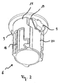
- Fig. 2 shows a perspective view of the cylindrical base body of the operating element 1.
- the formed as a rosette 6 main body preferably has wing-shaped locking elements 9 in the upper third of the rosette 6 in close proximity to the front ring 7.
- the outer geometry of the rosette 6 is structured, that is, there are both smooth surfaces 17 and recesses 18 on the outer edge of the rosette 6.
- the locking element 9 is arranged in a likewise wing-shaped recess 19 of the rosette 6, which opens into a guide channel 20 ,
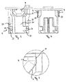
- Fig. 3 shows a sectional view of the cylindrical base body of the operating element 1 with a front view of the locking element 9 according to the invention.
- the locking element 9 is arranged in the similarly shaped recess 19, which opens into the guide channel 20.
- the guide channel 20 is formed by two right and left of the guide channel 20 formed edge structures 21, 22. These edge structures 21, 22 have guide slopes 23 and recesses 24, which allow a targeted insertion and locking of the rosette 6 in the holding element 4.
- Fig. 4 shows a sectional view of the cylindrical base body of the operating element 1 with a side view of the locking elements 9.
- the locking elements 9 have in addition to the insertion bevels 11 and insertion radii 25, which facilitate the targeted insertion and locking of the rosette 6.
- Fig. 5 shows a sectional view of an enlarged detail Fig. 3 Shown are also the flanks 10 of the latching wing element and the insertion bevels 11th
- Fig. 6 shows a perspective view of lying on the front ring 7 control element 1 with molded plastic wing, the in Fig. 7 also shown again in an enlarged section.
- Such an embodiment with directly molded plastic wing is then provided when the rosette 6 is made of plastic.
- Fig. 8 shows a perspective view of lying on the front ring 7 control element 1 with pressed plastic wing, the in Fig. 9 also shown again in an enlarged section.
- a dome-shaped projection 26 is preferably arranged on the rosette 6. This projection 26 opens when pressing the plastic wing in a hole member 27, which is preferably centered in the plastic wing is arranged.
- Fig. 10 shows a perspective view of an operating element 1 with an accessory 28th
- Fig. 11 shows a bottom view of the control element 1 with accessory 28.
- the flanks 10 of the locking elements 9 are applied to tooth flanks 29 of the accessory 28 at.
- These tooth flanks 29 are preferably arranged at defined intervals, for example in 90 ° steps, so that the operating element 1 can be positioned without defined components at defined distances from the accessory 28. If the position is chosen incorrectly, the accessory 28 can simply be further rotated to finally re-engage in the following position.
- Fig. 12 The functionless closure stopper 30 or dummy plugs offer in their inner space for receiving a molded spring element 31.
- the insertion radii 31 (FIG. Fig. 13 ).
- Fig. 13 shows a bottom view of the functionless sealing plug 30 after Fig. 12 .
- control element according to the invention with improved installation unit allows easy one-handed installation, which is implemented via locking elements.
Landscapes
- Engineering & Computer Science (AREA)
- Power Engineering (AREA)
- Casings For Electric Apparatus (AREA)
- Connection Of Plates (AREA)
- Valve Housings (AREA)
Claims (8)
- Elément de commande comportant une unité de montage, qui présente une plaque frontale (3) ainsi qu'un élément de maintien (4), l'élément de commande (1) présentant une rosette (6) et une bague frontale (7) posée dessus et au moins un élément encliquetable (9) et pouvant être introduit dans l'élément de maintien (4) par enclenchement à travers un passage (15) dans la plaque frontale (3) par le biais de l'au moins un élément encliquetable (4), caractérisé en ce que l'élément encliquetable (9) est réalisé en tant qu'ailette avec une pente d'introduction (11), l'élément encliquetable (9) en forme d'ailette étant disposé dans le tiers supérieur de la rosette (6) à proximité directe de la bague frontale (7), et l'élément encliquetable (9) étant disposé dans un évidement (19) de la rosette réalisé en forme d'ailette qui débouche dans un canal de guidage (20).
- Elément de commande selon la revendication 1, caractérisé en ce que la plaque frontale (3) est fixée de manière inamovible par le biais de l'au moins un élément encliquetable (9) à l'élément de commande (1).
- Elément de commande selon la revendication 1 ou 2, caractérisé en ce que l'élément encliquetable (9) est fabriqué en matière plastique.
- Elément de commande selon l'une des revendications précédentes, caractérisé en ce que l'au moins un élément encliquetable (9) est réalisé de manière élastique.
- Elément de commande selon l'une des revendications précédentes, caractérisé en ce que l'élément encliquetable (9) présente des rayons d'introduction (25).
- Elément de commande selon l'une des revendications précédentes, caractérisé en ce que l'élément de commande (1) présente une bague frontale (7) et une rosette (6) au niveau de laquelle l'au moins un élément encliquetable (9) est appliqué par injection.
- Elément de commande selon l'une des revendications précédentes, caractérisé en ce que dans le cas d'éléments de commande (1) comportant une rosette métallique l'au moins un élément encliquetable (9) est engagé par pression.
- Elément de commande selon la revendication 1, caractérisé en ce que l'élément de commande est réalisé en tant que bouchon de fermeture non fonctionnel (30) avec la rosette (6).
Applications Claiming Priority (1)
| Application Number | Priority Date | Filing Date | Title |
|---|---|---|---|
| PCT/EP2008/005780 WO2010006625A1 (fr) | 2008-07-15 | 2008-07-15 | Élément de commande comportant une unité de montage |
Publications (2)
| Publication Number | Publication Date |
|---|---|
| EP2301123A1 EP2301123A1 (fr) | 2011-03-30 |
| EP2301123B1 true EP2301123B1 (fr) | 2013-10-02 |
Family
ID=40473603
Family Applications (1)
| Application Number | Title | Priority Date | Filing Date |
|---|---|---|---|
| EP08784788.5A Not-in-force EP2301123B1 (fr) | 2008-07-15 | 2008-07-15 | Élément de commande comportant une unité de montage |
Country Status (4)
| Country | Link |
|---|---|
| EP (1) | EP2301123B1 (fr) |
| CN (1) | CN102084562B (fr) |
| BR (1) | BRPI0822941B1 (fr) |
| WO (1) | WO2010006625A1 (fr) |
Families Citing this family (1)
| Publication number | Priority date | Publication date | Assignee | Title |
|---|---|---|---|---|
| DE102010041041A1 (de) * | 2010-09-20 | 2012-03-22 | Siemens Aktiengesellschaft | Installationseinheit für die Fixierung von Befehls- und Meldegeräten an Frontplatten |
Family Cites Families (5)
| Publication number | Priority date | Publication date | Assignee | Title |
|---|---|---|---|---|
| DE2609473C3 (de) * | 1976-03-08 | 1978-11-30 | Pistor & Kroenert, Gmbh U. Co, 5880 Luedenscheid | Elektrisches Installationsgerät (Signalleuchte, Schaltgerät u.dgl.) zum Einbau in eine öffnung einer Trägerplatte |
| DE3014368C2 (de) * | 1980-04-15 | 1983-10-27 | R. Stahl Schaltgeräte GmbH, 7118 Künzelsau | Schalttafeleinbaugerät zur Einlochmontage in Schalttafeln |
| CH666952A5 (fr) * | 1986-04-24 | 1988-08-31 | Universo Sa | Porte-lampe miniature. |
| US5542859A (en) * | 1994-11-16 | 1996-08-06 | Woods Industries, Inc. | Quick mount electrical wall socket |
| DE10330853B4 (de) * | 2003-07-09 | 2006-08-03 | WEG Indústrias S.A., Jaraguá do Sul | Schnappmechanismus für das Befestigen eines Flansches an eine Befehls- oder Meldeeinheit |
-
2008
- 2008-07-15 CN CN200880130206.9A patent/CN102084562B/zh not_active Expired - Fee Related
- 2008-07-15 WO PCT/EP2008/005780 patent/WO2010006625A1/fr not_active Ceased
- 2008-07-15 BR BRPI0822941A patent/BRPI0822941B1/pt not_active IP Right Cessation
- 2008-07-15 EP EP08784788.5A patent/EP2301123B1/fr not_active Not-in-force
Also Published As
| Publication number | Publication date |
|---|---|
| BRPI0822941B1 (pt) | 2019-01-22 |
| WO2010006625A1 (fr) | 2010-01-21 |
| CN102084562A (zh) | 2011-06-01 |
| CN102084562B (zh) | 2014-01-15 |
| EP2301123A1 (fr) | 2011-03-30 |
| BRPI0822941A2 (pt) | 2018-03-13 |
Similar Documents
| Publication | Publication Date | Title |
|---|---|---|
| EP1269580A1 (fr) | Module electronique | |
| WO2009062698A1 (fr) | Mécanisme d'entraînement pour porte avec unité d'entraînement | |
| DE102020104994A1 (de) | Kabeleinlassvorrichtung für einen Schaltschrank sowie Anordnung und Verfahren zum Betrieb derselben | |
| WO2009115080A2 (fr) | Dispositif permettant de réaliser une connexion électrique sèche d'une serrure de véhicule automobile | |
| EP1398223B1 (fr) | Dispositif de fixation d'une peau de pare-chocs sur un véhicule, un véhicule automobile en particulier | |
| EP2301123B1 (fr) | Élément de commande comportant une unité de montage | |
| EP2704273B1 (fr) | Dispositif de commande et de signalisation destiné à être monté dans l'orifice de montage d'une plaque de montage | |
| EP3081728B2 (fr) | Serrure de véhicule automobile | |
| DE102020126918A1 (de) | Gehäuseanordnung für einen elektrischen Stecker mit einem Bedienungshebel sowie elektrischer Stecker und Steckeranordnung | |
| EP2704272B1 (fr) | Dispositif de commande et de signalisation destine a etre monte dans l'orifice de montage d'une plaque de montage | |
| DE202012008253U1 (de) | Befehls- und Meldegerät | |
| DE102010041041A1 (de) | Installationseinheit für die Fixierung von Befehls- und Meldegeräten an Frontplatten | |
| DE19925859B4 (de) | Montagehilfe für eine Kraftfahrzeugtürkonstruktion | |
| DE202010000903U1 (de) | Vorrichtung zur Zugentlastung und Gehäusewand-Durchführung von Litzen und Encoder | |
| EP2960914B1 (fr) | Procédé de fabrication d'un composant compact à bouton poussoir | |
| EP2697542B1 (fr) | Dispositif de commande et de signalisation | |
| EP1355387B1 (fr) | Assemblage de connecteur électrique sur une pièce fixe de carrosserie de véhicule et procédé pour la formation d'un tel assemblage de connecteur électrique | |
| DE102021121544A1 (de) | Elektromotorische Stellvorrichtung für kraftfahrzeugtechnische Anwendungen | |
| DE102022107510A1 (de) | Antriebseinheit für kraftfahrzeug-technische Anwendungen | |
| WO2002046558A1 (fr) | Dispositif d'actionnement pouvant etre monte dans une ouverture de paroi et etant destinee a des serrures de vehicule | |
| DE202012008252U1 (de) | Befehls- und Meldegerät | |
| EP4544137A1 (fr) | Ensemble serrure de véhicule à moteur et son procédé de fabrication | |
| WO2009003917A1 (fr) | Module de colonne de direction pour un véhicule automobile | |
| DE102011078639A1 (de) | Befehls- und Meldevorrichtung | |
| DE202012008258U1 (de) | Befehls- und Meldegerät |
Legal Events
| Date | Code | Title | Description |
|---|---|---|---|
| PUAI | Public reference made under article 153(3) epc to a published international application that has entered the european phase |
Free format text: ORIGINAL CODE: 0009012 |
|
| 17P | Request for examination filed |
Effective date: 20101202 |
|
| AK | Designated contracting states |
Kind code of ref document: A1 Designated state(s): AT BE BG CH CY CZ DE DK EE ES FI FR GB GR HR HU IE IS IT LI LT LU LV MC MT NL NO PL PT RO SE SI SK TR |
|
| AX | Request for extension of the european patent |
Extension state: AL BA MK RS |
|
| RIN1 | Information on inventor provided before grant (corrected) |
Inventor name: BECK, RONNY Inventor name: HIRSCHBERGER, FRANK |
|
| DAX | Request for extension of the european patent (deleted) | ||
| RAP1 | Party data changed (applicant data changed or rights of an application transferred) |
Owner name: SIEMENS AKTIENGESELLSCHAFT |
|
| GRAP | Despatch of communication of intention to grant a patent |
Free format text: ORIGINAL CODE: EPIDOSNIGR1 |
|
| INTG | Intention to grant announced |
Effective date: 20130422 |
|
| GRAS | Grant fee paid |
Free format text: ORIGINAL CODE: EPIDOSNIGR3 |
|
| GRAA | (expected) grant |
Free format text: ORIGINAL CODE: 0009210 |
|
| AK | Designated contracting states |
Kind code of ref document: B1 Designated state(s): AT BE BG CH CY CZ DE DK EE ES FI FR GB GR HR HU IE IS IT LI LT LU LV MC MT NL NO PL PT RO SE SI SK TR |
|
| REG | Reference to a national code |
Ref country code: GB Ref legal event code: FG4D Free format text: NOT ENGLISH |
|
| REG | Reference to a national code |
Ref country code: CH Ref legal event code: EP Ref country code: AT Ref legal event code: REF Ref document number: 635025 Country of ref document: AT Kind code of ref document: T Effective date: 20131015 |
|
| REG | Reference to a national code |
Ref country code: IE Ref legal event code: FG4D Free format text: LANGUAGE OF EP DOCUMENT: GERMAN |
|
| REG | Reference to a national code |
Ref country code: DE Ref legal event code: R096 Ref document number: 502008010758 Country of ref document: DE Effective date: 20131128 |
|
| REG | Reference to a national code |
Ref country code: NL Ref legal event code: VDEP Effective date: 20131002 |
|
| PG25 | Lapsed in a contracting state [announced via postgrant information from national office to epo] |
Ref country code: SI Free format text: LAPSE BECAUSE OF FAILURE TO SUBMIT A TRANSLATION OF THE DESCRIPTION OR TO PAY THE FEE WITHIN THE PRESCRIBED TIME-LIMIT Effective date: 20131002 |
|
| REG | Reference to a national code |
Ref country code: LT Ref legal event code: MG4D |
|
| PG25 | Lapsed in a contracting state [announced via postgrant information from national office to epo] |
Ref country code: NO Free format text: LAPSE BECAUSE OF FAILURE TO SUBMIT A TRANSLATION OF THE DESCRIPTION OR TO PAY THE FEE WITHIN THE PRESCRIBED TIME-LIMIT Effective date: 20140102 Ref country code: FI Free format text: LAPSE BECAUSE OF FAILURE TO SUBMIT A TRANSLATION OF THE DESCRIPTION OR TO PAY THE FEE WITHIN THE PRESCRIBED TIME-LIMIT Effective date: 20131002 Ref country code: NL Free format text: LAPSE BECAUSE OF FAILURE TO SUBMIT A TRANSLATION OF THE DESCRIPTION OR TO PAY THE FEE WITHIN THE PRESCRIBED TIME-LIMIT Effective date: 20131002 Ref country code: IS Free format text: LAPSE BECAUSE OF FAILURE TO SUBMIT A TRANSLATION OF THE DESCRIPTION OR TO PAY THE FEE WITHIN THE PRESCRIBED TIME-LIMIT Effective date: 20140202 Ref country code: LT Free format text: LAPSE BECAUSE OF FAILURE TO SUBMIT A TRANSLATION OF THE DESCRIPTION OR TO PAY THE FEE WITHIN THE PRESCRIBED TIME-LIMIT Effective date: 20131002 Ref country code: SE Free format text: LAPSE BECAUSE OF FAILURE TO SUBMIT A TRANSLATION OF THE DESCRIPTION OR TO PAY THE FEE WITHIN THE PRESCRIBED TIME-LIMIT Effective date: 20131002 Ref country code: CZ Free format text: LAPSE BECAUSE OF FAILURE TO SUBMIT A TRANSLATION OF THE DESCRIPTION OR TO PAY THE FEE WITHIN THE PRESCRIBED TIME-LIMIT Effective date: 20131002 Ref country code: HR Free format text: LAPSE BECAUSE OF FAILURE TO SUBMIT A TRANSLATION OF THE DESCRIPTION OR TO PAY THE FEE WITHIN THE PRESCRIBED TIME-LIMIT Effective date: 20131002 |
|
| PG25 | Lapsed in a contracting state [announced via postgrant information from national office to epo] |
Ref country code: PL Free format text: LAPSE BECAUSE OF FAILURE TO SUBMIT A TRANSLATION OF THE DESCRIPTION OR TO PAY THE FEE WITHIN THE PRESCRIBED TIME-LIMIT Effective date: 20131002 Ref country code: CY Free format text: LAPSE BECAUSE OF FAILURE TO SUBMIT A TRANSLATION OF THE DESCRIPTION OR TO PAY THE FEE WITHIN THE PRESCRIBED TIME-LIMIT Effective date: 20131002 Ref country code: LV Free format text: LAPSE BECAUSE OF FAILURE TO SUBMIT A TRANSLATION OF THE DESCRIPTION OR TO PAY THE FEE WITHIN THE PRESCRIBED TIME-LIMIT Effective date: 20131002 Ref country code: ES Free format text: LAPSE BECAUSE OF FAILURE TO SUBMIT A TRANSLATION OF THE DESCRIPTION OR TO PAY THE FEE WITHIN THE PRESCRIBED TIME-LIMIT Effective date: 20131002 |
|
| PG25 | Lapsed in a contracting state [announced via postgrant information from national office to epo] |
Ref country code: PT Free format text: LAPSE BECAUSE OF FAILURE TO SUBMIT A TRANSLATION OF THE DESCRIPTION OR TO PAY THE FEE WITHIN THE PRESCRIBED TIME-LIMIT Effective date: 20140203 |
|
| REG | Reference to a national code |
Ref country code: DE Ref legal event code: R097 Ref document number: 502008010758 Country of ref document: DE |
|
| PG25 | Lapsed in a contracting state [announced via postgrant information from national office to epo] |
Ref country code: EE Free format text: LAPSE BECAUSE OF FAILURE TO SUBMIT A TRANSLATION OF THE DESCRIPTION OR TO PAY THE FEE WITHIN THE PRESCRIBED TIME-LIMIT Effective date: 20131002 |
|
| PLBE | No opposition filed within time limit |
Free format text: ORIGINAL CODE: 0009261 |
|
| STAA | Information on the status of an ep patent application or granted ep patent |
Free format text: STATUS: NO OPPOSITION FILED WITHIN TIME LIMIT |
|
| PG25 | Lapsed in a contracting state [announced via postgrant information from national office to epo] |
Ref country code: RO Free format text: LAPSE BECAUSE OF FAILURE TO SUBMIT A TRANSLATION OF THE DESCRIPTION OR TO PAY THE FEE WITHIN THE PRESCRIBED TIME-LIMIT Effective date: 20131002 Ref country code: SK Free format text: LAPSE BECAUSE OF FAILURE TO SUBMIT A TRANSLATION OF THE DESCRIPTION OR TO PAY THE FEE WITHIN THE PRESCRIBED TIME-LIMIT Effective date: 20131002 |
|
| 26N | No opposition filed |
Effective date: 20140703 |
|
| PG25 | Lapsed in a contracting state [announced via postgrant information from national office to epo] |
Ref country code: DK Free format text: LAPSE BECAUSE OF FAILURE TO SUBMIT A TRANSLATION OF THE DESCRIPTION OR TO PAY THE FEE WITHIN THE PRESCRIBED TIME-LIMIT Effective date: 20131002 |
|
| REG | Reference to a national code |
Ref country code: DE Ref legal event code: R097 Ref document number: 502008010758 Country of ref document: DE Effective date: 20140703 |
|
| PG25 | Lapsed in a contracting state [announced via postgrant information from national office to epo] |
Ref country code: LU Free format text: LAPSE BECAUSE OF FAILURE TO SUBMIT A TRANSLATION OF THE DESCRIPTION OR TO PAY THE FEE WITHIN THE PRESCRIBED TIME-LIMIT Effective date: 20140715 |
|
| REG | Reference to a national code |
Ref country code: CH Ref legal event code: PL |
|
| GBPC | Gb: european patent ceased through non-payment of renewal fee |
Effective date: 20140715 |
|
| REG | Reference to a national code |
Ref country code: IE Ref legal event code: MM4A |
|
| PG25 | Lapsed in a contracting state [announced via postgrant information from national office to epo] |
Ref country code: LI Free format text: LAPSE BECAUSE OF NON-PAYMENT OF DUE FEES Effective date: 20140731 Ref country code: CH Free format text: LAPSE BECAUSE OF NON-PAYMENT OF DUE FEES Effective date: 20140731 |
|
| PG25 | Lapsed in a contracting state [announced via postgrant information from national office to epo] |
Ref country code: GB Free format text: LAPSE BECAUSE OF NON-PAYMENT OF DUE FEES Effective date: 20140715 |
|
| PG25 | Lapsed in a contracting state [announced via postgrant information from national office to epo] |
Ref country code: IE Free format text: LAPSE BECAUSE OF NON-PAYMENT OF DUE FEES Effective date: 20140715 |
|
| REG | Reference to a national code |
Ref country code: AT Ref legal event code: MM01 Ref document number: 635025 Country of ref document: AT Kind code of ref document: T Effective date: 20140715 |
|
| PG25 | Lapsed in a contracting state [announced via postgrant information from national office to epo] |
Ref country code: AT Free format text: LAPSE BECAUSE OF NON-PAYMENT OF DUE FEES Effective date: 20140715 |
|
| PG25 | Lapsed in a contracting state [announced via postgrant information from national office to epo] |
Ref country code: NO Free format text: LAPSE BECAUSE OF FAILURE TO SUBMIT A TRANSLATION OF THE DESCRIPTION OR TO PAY THE FEE WITHIN THE PRESCRIBED TIME-LIMIT Effective date: 20140101 Ref country code: MC Free format text: LAPSE BECAUSE OF FAILURE TO SUBMIT A TRANSLATION OF THE DESCRIPTION OR TO PAY THE FEE WITHIN THE PRESCRIBED TIME-LIMIT Effective date: 20131002 |
|
| PG25 | Lapsed in a contracting state [announced via postgrant information from national office to epo] |
Ref country code: BG Free format text: LAPSE BECAUSE OF FAILURE TO SUBMIT A TRANSLATION OF THE DESCRIPTION OR TO PAY THE FEE WITHIN THE PRESCRIBED TIME-LIMIT Effective date: 20131002 |
|
| PG25 | Lapsed in a contracting state [announced via postgrant information from national office to epo] |
Ref country code: MT Free format text: LAPSE BECAUSE OF FAILURE TO SUBMIT A TRANSLATION OF THE DESCRIPTION OR TO PAY THE FEE WITHIN THE PRESCRIBED TIME-LIMIT Effective date: 20131002 Ref country code: GR Free format text: LAPSE BECAUSE OF FAILURE TO SUBMIT A TRANSLATION OF THE DESCRIPTION OR TO PAY THE FEE WITHIN THE PRESCRIBED TIME-LIMIT Effective date: 20140103 |
|
| REG | Reference to a national code |
Ref country code: FR Ref legal event code: PLFP Year of fee payment: 9 |
|
| PG25 | Lapsed in a contracting state [announced via postgrant information from national office to epo] |
Ref country code: BE Free format text: LAPSE BECAUSE OF FAILURE TO SUBMIT A TRANSLATION OF THE DESCRIPTION OR TO PAY THE FEE WITHIN THE PRESCRIBED TIME-LIMIT Effective date: 20140731 Ref country code: HU Free format text: LAPSE BECAUSE OF FAILURE TO SUBMIT A TRANSLATION OF THE DESCRIPTION OR TO PAY THE FEE WITHIN THE PRESCRIBED TIME-LIMIT; INVALID AB INITIO Effective date: 20080715 Ref country code: TR Free format text: LAPSE BECAUSE OF FAILURE TO SUBMIT A TRANSLATION OF THE DESCRIPTION OR TO PAY THE FEE WITHIN THE PRESCRIBED TIME-LIMIT Effective date: 20131002 |
|
| REG | Reference to a national code |
Ref country code: FR Ref legal event code: PLFP Year of fee payment: 10 |
|
| REG | Reference to a national code |
Ref country code: FR Ref legal event code: PLFP Year of fee payment: 11 |
|
| PGFP | Annual fee paid to national office [announced via postgrant information from national office to epo] |
Ref country code: DE Payment date: 20190919 Year of fee payment: 12 Ref country code: FR Payment date: 20190716 Year of fee payment: 12 Ref country code: IT Payment date: 20190729 Year of fee payment: 12 |
|
| REG | Reference to a national code |
Ref country code: DE Ref legal event code: R119 Ref document number: 502008010758 Country of ref document: DE |
|
| PG25 | Lapsed in a contracting state [announced via postgrant information from national office to epo] |
Ref country code: FR Free format text: LAPSE BECAUSE OF NON-PAYMENT OF DUE FEES Effective date: 20200731 |
|
| PG25 | Lapsed in a contracting state [announced via postgrant information from national office to epo] |
Ref country code: DE Free format text: LAPSE BECAUSE OF NON-PAYMENT OF DUE FEES Effective date: 20210202 |
|
| PG25 | Lapsed in a contracting state [announced via postgrant information from national office to epo] |
Ref country code: IT Free format text: LAPSE BECAUSE OF NON-PAYMENT OF DUE FEES Effective date: 20200715 |