EP2301668A1 - Brause mit drehbarem Brausekopf - Google Patents
Brause mit drehbarem Brausekopf Download PDFInfo
- Publication number
- EP2301668A1 EP2301668A1 EP10178965A EP10178965A EP2301668A1 EP 2301668 A1 EP2301668 A1 EP 2301668A1 EP 10178965 A EP10178965 A EP 10178965A EP 10178965 A EP10178965 A EP 10178965A EP 2301668 A1 EP2301668 A1 EP 2301668A1
- Authority
- EP
- European Patent Office
- Prior art keywords
- shower
- sealing
- opening
- inlet
- flow
- Prior art date
- Legal status (The legal status is an assumption and is not a legal conclusion. Google has not performed a legal analysis and makes no representation as to the accuracy of the status listed.)
- Granted
Links
- 238000007789 sealing Methods 0.000 claims description 123
- 238000005192 partition Methods 0.000 claims description 9
- 230000007704 transition Effects 0.000 claims description 7
- 238000011144 upstream manufacturing Methods 0.000 claims description 3
- 229920002725 thermoplastic elastomer Polymers 0.000 claims 1
- 239000012530 fluid Substances 0.000 abstract 1
- XLYOFNOQVPJJNP-UHFFFAOYSA-N water Substances O XLYOFNOQVPJJNP-UHFFFAOYSA-N 0.000 description 19
- 238000006073 displacement reaction Methods 0.000 description 3
- 230000000694 effects Effects 0.000 description 2
- 238000010276 construction Methods 0.000 description 1
- 230000008878 coupling Effects 0.000 description 1
- 238000010168 coupling process Methods 0.000 description 1
- 238000005859 coupling reaction Methods 0.000 description 1
- 230000005489 elastic deformation Effects 0.000 description 1
- 238000001746 injection moulding Methods 0.000 description 1
- 238000004519 manufacturing process Methods 0.000 description 1
- 239000000463 material Substances 0.000 description 1
- 238000005457 optimization Methods 0.000 description 1
- 230000002093 peripheral effect Effects 0.000 description 1
- 239000000243 solution Substances 0.000 description 1
- 239000012815 thermoplastic material Substances 0.000 description 1
Images


Classifications
-
- B—PERFORMING OPERATIONS; TRANSPORTING
- B05—SPRAYING OR ATOMISING IN GENERAL; APPLYING FLUENT MATERIALS TO SURFACES, IN GENERAL
- B05B—SPRAYING APPARATUS; ATOMISING APPARATUS; NOZZLES
- B05B1/00—Nozzles, spray heads or other outlets, with or without auxiliary devices such as valves, heating means
- B05B1/14—Nozzles, spray heads or other outlets, with or without auxiliary devices such as valves, heating means with multiple outlet openings; with strainers in or outside the outlet opening
- B05B1/18—Roses; Shower heads
-
- B—PERFORMING OPERATIONS; TRANSPORTING
- B05—SPRAYING OR ATOMISING IN GENERAL; APPLYING FLUENT MATERIALS TO SURFACES, IN GENERAL
- B05B—SPRAYING APPARATUS; ATOMISING APPARATUS; NOZZLES
- B05B1/00—Nozzles, spray heads or other outlets, with or without auxiliary devices such as valves, heating means
- B05B1/14—Nozzles, spray heads or other outlets, with or without auxiliary devices such as valves, heating means with multiple outlet openings; with strainers in or outside the outlet opening
- B05B1/16—Nozzles, spray heads or other outlets, with or without auxiliary devices such as valves, heating means with multiple outlet openings; with strainers in or outside the outlet opening having selectively- effective outlets
- B05B1/1627—Nozzles, spray heads or other outlets, with or without auxiliary devices such as valves, heating means with multiple outlet openings; with strainers in or outside the outlet opening having selectively- effective outlets with a selecting mechanism comprising a gate valve, a sliding valve or a cock
- B05B1/1636—Nozzles, spray heads or other outlets, with or without auxiliary devices such as valves, heating means with multiple outlet openings; with strainers in or outside the outlet opening having selectively- effective outlets with a selecting mechanism comprising a gate valve, a sliding valve or a cock by relative rotative movement of the valve elements
- B05B1/1645—Nozzles, spray heads or other outlets, with or without auxiliary devices such as valves, heating means with multiple outlet openings; with strainers in or outside the outlet opening having selectively- effective outlets with a selecting mechanism comprising a gate valve, a sliding valve or a cock by relative rotative movement of the valve elements the outlets being rotated during selection
Definitions
- the invention relates to a shower head with rotatable shower head, which is rotatably mounted in a shower housing and which has at least one chamber which communicates with an inlet opening on the outer circumference, which inlet opening can be radially outflowed from a feed element integrated in the shower housing.
- Such a shower is known as a hand shower. Due to the radial water supply a very flat design is possible. Water is supplied through the shower housing and passed through an inlet unit with a seal to the inlet opening in the shower head. The shower head can be rotated in certain angular steps, so that in each case a different inlet opening is positioned in front of the inlet unit.
- the sealing element is pressed by means of a spring on the outer circumference of the rotatable shower head in the inlet unit. In this case, however, sealing problems have been shown, since the pressed-in by means of spring sealing element tilted slightly and himself deformed unevenly by the spring force.
- the object of the invention is thus to improve in a shower of the type mentioned sealing the water transfer from the showerhead to the shower head.
- the rounding of the sealing element on its rear side is chosen such that the radius of curvature corresponds to the radius R of the shower head when the seal is applied to the shower head.
- the radius of curvature is either exactly equal to the shower head radius R or over or under dimensions or not exactly circular arc-shaped forms are provided to take into account elastic deformations which occur when pressure on the shower head.
- a section of an elliptical contour may be selected for the sealing element.
- the sealing chamber with respect to the feed element in the shower housing by a partition with divided off an inlet opening.
- the axial displacement is limited and it is prevented that the sealing element, for example, in the case of a negative pressure in the water supply is drawn too far into the shower housing into it and jammed there.
- sealing element not a loosely inserted sealing element as a whole, but only an annular, membrane-like sealing skin whose edge facing the inner flow opening is formed as a sealing lip, which is designed and determined for engagement with the round body of the rotatable shower head.
- the sealing lip thus lifts off due to their material-related elastic restoring forces of the body of the shower head when no water pressure is present.
- the sealing element is in particular in the two-component injection molding process molded directly onto the shower enclosure.
- the mounting of the shower according to the invention reduces to the onset of the rotatable shower head in the shower housing and possibly even the fixation with a screw placed on the axis of rotation.
- the inventive construction of the sealing unit offers particular advantages for a rotatable shower head, which has a plurality of functional zones, each opening into individual inlet openings and can be controlled separately.
- the flow opening of the seal preferably always covers one of the inlet openings, at least partially, in all positions of the shower head. This avoids that in any position of the shower head abruptly the full line water pressure acts on the sealing element and on the backflow to the shower housing.
- a contour is favorably formed according to the shape of a lying eight or an hourglass, where there are correspondingly large opening heights at the edge, in the respective covering area with the inlet opening.
- the volume flow is variable, for example, by means of a flow limitation initially with a soft jet during showering to save water and then wash out the hair with a hard jet.
- a water-saving function is favored by a wedge shape of the flow opening.
- the cross section of the sealing chamber and the sealing element itself are elliptical or oblong hole-shaped.
- the non-circular shape counteracts tilting of the sealing element in the sealing chamber.
- the desirable for the design of the hand shower flat design can be maintained by the greater width of the shower housing is exploited to provide a correspondingly large pressure acting surface.
- the lateral areas of the sealing element cover an initially used inlet opening even when the shower head is already twisted, and also the next following in the direction of rotation inlet opening is initially covered by the filled areas of the sealing element behind the pressure acting surfaces until the next locking position of the shower head is finally reached and the next inlet opening of the shower head and the flow opening of the sealing element are back in alignment.
- the inlet opening of the sealing chamber should also be elliptical or oblong-shaped is and are preferably congruent before the sealing element.
- the flow from the inlet opening through the sealing chamber is performed evenly on the sealing element.
- the sealing element on the upstream side has a sealing collar protruding beyond the pressure acting surface.
- the sealing collar which is in particular thin and flexible, is applied radially outwardly against the walls of the sealing chamber, for which purpose the sealing collar preferably opens into a sealing tongue pointing outward against the wall of the sealing chamber. This prevents water from flowing past the outside of the sealing element.
- the outer contour of the sealing element can thereby be slightly smaller than the inner contour of the corresponding receptacle for the sealing element in the sealing chamber. Thus, a slight axial displaceability of the sealing element is given, and it suffice lower contact pressure and accordingly smaller pressure acting surfaces to effect the sealing function.
- the sealing element may have on its outer circumference at least one peripheral sealing projection which, viewed in particular in the flow direction, lies in front of or directly next to it the pressure acting surface is arranged.
- a guide of the sealing element at its seat in the sealing chamber at two points, namely at the front of the sealing lip and something behind at the sealing ledge. In between, there remains a gap which prevents tilting and jamming of the sealing element.
- the pressure acting surface is elliptical or elongated hole-shaped formed within the sealing collar and the central flow opening is circular and arranged in the center of the pressure acting surface.
- the flow is channeled so that it passes directly into the underlying, preferably also circular feed opening in the shower head.
- the non-circular shape of the pressure acting surface in turn makes maximum use of the available space in the sealing chamber.
- the inlet element through which water is conducted into the sealing chamber, can be formed by a cavity in the shower housing, ie a channel which extends from the lower end of the grip area, where a water hose is connected, to the sealing chamber.
- a hose may be inserted inside the showerhead.
- FIG. 1 shows a shower 100, which is formed in the example shown as a hand shower and consists essentially of a shower housing 10 and a rotatable therein shower head 20.
- the shower head 20 has a round contour with an outer radius R.
- the shower housing 10 has, in addition to a handle region with a feed channel 15 used as a feed element, a head region 16 which encloses the shower head 20 with a cylindrical wall. When displayed in FIG. 1 Both the shower head 20 as well as the head area 16, the respective cover surfaces are removed to release the view into the interior.
- the shower head 20 is divided in the illustrated embodiment into three chambers 21, 22, 23 and has at its bottom 27 in each chamber various nozzle elements.
- Each chamber 21, 22, 23 communicates with a respective inlet opening 24, 25, 26 on the outer circumference in connection - partially directly, partially via inlet channels.
- a partition 12 is arranged with a central inlet opening 14, which has an end portion of the inlet channel 15 divides, so that between the partition 12 and the outer periphery of the shower head 20, a sealing chamber 13 is formed.
- a sealing element 11 is placed, which completely covers the cross section of the sealing chamber 13.
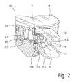
- the exact structure of the sealing unit results from FIG. 2 ,
- the sealing element 11 has a central flow opening 11.1.
- the surface areas right and left next to it are transverse to the flow direction and constitute a so-called pressure acting surface 11.2, at which the water pressure attack and can cause an axial displacement of the sealing element 11 in the flow direction.
- the inlet opening 14 on the partition wall 12 is formed so that its opening cross section is at least as large as the opening cross section of the flow opening 11.1. This avoids that the partition wall forms an effective flow obstruction, where there is a pressure drop.
- the pressure gradient must rather operate in operation so that between the water pressure in the seal chamber 13 and the water pressure beyond the inlet opening 24, 25 or 26, ie at a point within the shower head 20, there is a differential pressure.
- the sealing collar 11.3 has in the illustrated embodiment, at the front end of a sealing lip 11.5, which is inclined slightly obliquely outwards.
- the sealing collar has 11.3 on the outer circumference a sealing projection 11.4.
- the axial displacement of the sealing element 11 within the sealing chamber 13 is forward through the partition 12 limited in the shower housing 10 and back through the outer periphery of the shower head 20th
- the sum of the opening cross-sectional area in the central flow opening 11.1 and the pressure acting surface 11.2 in the sealing element 11, that is, the surface portion A seal within the sealing collar 11.3, should be 1.01 times to 25 times the area A projected perpendicular to the flow direction inlet of each of the inlet openings 24, 25 or 26 amount.
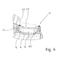
- FIG. 3 shows a head portion of a shower enclosure 10 'a shower 100'.
- a shower head can be rotatably mounted, as in Fig. 1 is formed, but for the sake of clarity, is not shown here.
- an elastomeric sealing element 11 ' is molded directly onto the shower housing 10'.
- the areas of the shower housing 10 'made of hard thermoplastic material are similar here as in the first embodiment, so that here at the end of a feed channel 15 also a sealing chamber 13 is introduced with upstream partition wall 12 with inlet opening 14, although the partition wall in the second embodiment functional is not essential.
- the sealing unit 11 ' is in FIG. 4 shown in detail. It can be seen there that extends the sealing lip 11.5 'of the boundary wall 17 of the seal chamber 13 from inside. Between the boundary wall 17 and the edge of the sealing lip 11.5 'or the outer edge of a Flow opening 11.1 'is thus an annular pressure-effective surface 11.2' is formed.
- FIGS. 5a to 5c is shown with reference to the sealing member 11 according to the first embodiment of a shower 100, as the overlap of the inlet openings 24, 25 or 26 through the flow opening 11.1 in the sealing element 11 works.
- the cylindrical jacket of the rotatable shower head 20 with its inlet openings 24, 25 and 26 is shown here as a development.
- the sealing element 11 is located in front of it.
- FIG. 5a the sealing element 11 is shown in front of the left inlet opening 24.
- the flow opening 11.1 lies approximately centrally in front of the inlet opening 24.
- the pressure-effective area 11.2 seals the surrounding area of the inlet opening 24 in total.
- FIG. 5a The arrow direction in FIG. 5a indicates the direction of movement.
- FIG. 5b The next following position shows FIG. 5b , In this case, the slot-shaped flow opening 11.1 still covers the left inlet opening 24 and the middle inlet opening 25 already.
- FIG. 5c Upon further rotation, the position will decrease FIG. 5c reached: there is the flow opening 11.1 in front of the central inlet opening 25 and seals the surrounding area.
Landscapes
- Nozzles (AREA)
- Bathtubs, Showers, And Their Attachments (AREA)
- Catching Or Destruction (AREA)
- Details Or Accessories Of Spraying Plant Or Apparatus (AREA)
Abstract
Description
- Die Erfindung betrifft eine Brause mit drehbarem Brausekopf, der in einem Brausengehäuse drehbar gelagert ist und der wenigstens eine Kammer aufweist, die mit einer Zulauföffnung am Außenumfang in Verbindung steht, welche Zulauföffnung aus einem in das Brausengehäuse integrierten Zulaufelement radial anströmbar ist.
- Aus der
DE 10 2007 002 894 B3 ist eine solche Brause als Handbrause bekannt. Durch die radiale Wassereinspeisung ist eine sehr flache Bauweise möglich. Wasser wird über das Brausengehäuse zugeführt und über eine Zulaufeinheit mit einer Dichtung bis an die Zulauföffnung im Brausekopf geführt. Der Brausekopf kann in bestimmten Winkelschritten verdreht werden, so dass jeweils eine andere Zulauföffnung vor der Zulaufeinheit positioniert ist. Bei der bekannten Handbrause wird in der Zulaufeinheit das Dichtungselement mittels einer Feder an den Außenumfang des drehbaren Brausekopfes angepresst. Dabei haben sich jedoch Dichtungsprobleme gezeigt, da das mittels Federkraft angepresste Dichtungselement leicht verkantet und sich durch die Federkraft ungleichmäßig verformt. Die Optimierung der Dichtstelle ist auch deshalb schwierig, weil einerseits eine hohe Anpresskraft erforderlich ist, um die Dichtwirkung herbeizuführen, andererseits aber eine hohe Anpresskraft die einfache Verstellbarkeit des Brausekopfes behindert, insbesondere wenn dieser noch trocken ist und ein hoher Reibungskoeffizient zwischen Brausekopf und Dichtungselement gegeben ist. - Aufgabe der Erfindung ist es somit, bei einer Brause der eingangs genannten Art die Abdichtung der Wasserüberleitung vom Brausengehäuse zum Brausekopf zu verbessern.
- Gelöst wird diese Aufgabe gemäß einer ersten Ausführungsform nach Anspruch 1 dadurch, dass im Brausengehäuse im Übergang von dem Zulaufelement zu der Zulauföffnung eine federlose Dichtungseinheit ausgebildet ist, die eine Dichtungskammer und wenigstens ein darin eingesetztes Dichtungselement umfasst, welches:
- in Strömungsrichtung verschiebbar in der Dichtungskammer geführt ist,
- außerhalb der lichten Öffnungsweite seiner zentralen Strömungsöffnung wenigstens eine quer zur Strömungsrichtung im Fließkanal ausgerichtete Druckwirkfläche aufweist und
- an seiner in Strömungsrichtung gesehen rückwärtigen Seite konkav gerundet ausgebildet ist, wobei der Rundungsradius dem Radius R des Brausekopfes entspricht.
- Durch die Koppelung der Dichtfunktion an den Wasserdruck wird erreicht, dass der Benutzer vor Gebrauch, auch bei noch trockenem Brausekopf, den Brausekopf ohne einen großen von der Dichtungseinheit her rührenden Widerstand verdrehen kann, um die gewünschte Funktionszone des Brausekopfes auszuwählen.
- Mit Öffnen der Wasserzufuhr stellt sich in der Dichtungseinheit ein bestimmter Staudruck ein, da durch die im Querschnitt reduzierte Strömungsöffnung im Dichtungselement eine Engstelle gebildet wird. Die Anpresskraft, die auf das Dichtungselement wirkt, ergibt sich dann aus dem Produkt der Größe der Druckwirkfläche und dem in der Dichtungskammer anstehenden Staudruck. Sobald der Wasserdruck abfällt, reduziert sich die Anpresskraft, mit der das Dichtungselement an den Außenumfang des Brausekopfes angepresst wird, so dass der Benutzer wieder bequem die nächste Einstellung vornehmen kann.
- Als weiterer Vorteil ergeben sich geringere Herstellungsund Montagekosten, insbesondere weil die Dichteinheit ganz ohne Federelement, insbesondere ein Spiralfederelement, aufgebaut ist.
- Die Rundung des Dichtungselements an seiner rückwärtigen Seite ist derart gewählt, dass der Rundungsradius bei Anliegen der Dichtung am Brausekopf dem Radius R des Brausekopfes entspricht. Im unbelasteten Zustand ist deshalb der Rundungsradius entweder exakt gleich zum Brausekopfradius R oder es sind Über- oder Untermaße oder auch nicht exakt kreisbogenförmige Formen vorgesehen, um elastische Verformungen zu berücksichtigen, welche bei Andruck an den Brausekopf auftreten. Beispielsweise kann auch ein Abschnitt einer elliptischen Kontur für das Dichtungselement gewählt sein.
- Vorzugsweise ist die Dichtungskammer gegenüber dem Zulaufelement im Brausengehäuse durch eine Trennwand mit einer Zulauföffnung abgeteilt. Damit wird der axiale Verschiebeweg begrenzt und es wird verhindert, dass das Dichtungselement z.B. im Falle eines Unterdrucks in der Wasserzuführung zu weit in das Brausengehäuse hinein gezogen wird und dort verklemmt.
- Gemäß einer zweiten bevorzugten Ausführungsform der Erfindung gemäß Anspruch 6 wird die Lösung der Aufgabe dadurch erreicht, dass im Brausengehäuse am Übergang von dem Zulaufelement zu der Zulauföffnung eine Dichtungseinheit ausgebildet ist, die eine Dichtungskammer mit wenigstens einem daran angebundenen Dichtungselement umfasst, welches:
- eine in Strömungsrichtung verschiebbare Dichtungslippe aufweist und
- außerhalb der lichten Öffnungsweite seiner zentralen Strömungsöffnung wenigstens eine quer zur Strömungsrichtung im Fließkanal ausgerichtete Druckwirkfläche aufweist.
- Hierbei bewegt sich also nicht ein lose eingesetztes Dichtelement als Ganzes, sondern nur eine ringförmige, membranartige Dichthaut, deren zur inneren Strömungsöffnung weisende Kante als eine Dichtlippe ausgebildet ist, die zur Anlage an den runden Körper des drehbaren Brausekopfes ausgebildet und bestimmt ist. Die Dichtlippe hebt also aufgrund ihrer materialbedingten elastischen Rückstellkräfte von dem Körper des Brausekopfes ab, wenn kein Wasserdruck ansteht. Wenn Wasser fließt, wird sie an den Umgebungsbereich der Zulauföffnung angepresst und dichtet den Wasserweg ab. Bei dieser Ausführungsform ist das Dichtelement insbesondere im Zweikomponenten-Spritzgussverfahren direkt an das Brausengehäuse angeformt.
- Damit reduziert sich die Montage der erfindungsgemäßen Brause auf das Einsetzen des drehbaren Brausekopfes in das Brausengehäuse und ggf. noch die Fixierung mit einer auf der Drehachse platzierten Schraube.
- Die erfindungsgemäße Ausbildung der Dichteinheit bietet besondere Vorteile für einen drehbaren Brausekopf, der mehrere Funktionszonen besitzt, die jeweils in einzelnen Zulauföffnungen münden und darüber separat angesteuert werden können.
- Vorzugsweise überdeckt die Strömungsöffnung der Dichtung in allen Stellungen des Brausekopfes immer eine der Zulauföffnungen, zumindest teilweise. Dadurch wird vermieden, dass in irgendeiner Position des Brausekopfes schlagartig der volle Leitungs-Wasserdruck auf das Dichtungselement und über den Rückstau auf das Brausegehäuse wirkt.
- Vorgesehen sein kann auch, dass in einer Mittenstellung zwei Kammern angeströmt werden und so deren jeweilige Strahlbilder gleichzeitig erzeugt werden. Hierfür ist eine Kontur günstig die nach Form einer liegenden Acht oder einer Sanduhr ausgebildet ist, wo es also randseitig, im jeweiligen Überdeckungsbereich mit der Zulauföffnung, entsprechend große Öffnungshöhen gibt.
- Möglich ist aber auch, nur eine Kammer im Brausekopf vorzusehen, und die Drehbarkeit des Brausekopfes dazu zu nutzen, die Wasserzufuhr an- und abzustellen oder sie variieren zu können.
- So kann durch die Abstimmung der Rastpositionen des Brausekopfes und der Form der Strömungsöffnung in dem Dichtungselement auch eine nur teilweise Überdeckung der Zulauföffnung bewirkt werden, so dass mit dem Drehen des Brausekopfes der Volumenstrom variierbar ist, beispielsweise um mittels einer Durchflussbegrenzung zunächst mit einem weichen Strahl während des Duschens Wasser zu sparen und anschließend mit einem harten Strahl die Haare auszuwaschen. Eine solche Wassersparfunktion wird durch eine Keilform der Strömungsöffnung begünstigt.
- Vorzugsweise sind der Querschnitt der Dichtungskammer und das Dichtungselement selbst elliptisch oder langlochförmig ausgebildet. Die unrunde Form wirkt einem Verkanten des Dichtungselements in der Dichtungskammer entgegen. Zudem kann die für das Design der Handbrause wünschenswerte flache Bauform beibehalten werden, indem die größere Breite des Brausengehäuses ausgenutzt wird, um eine entsprechend große Druckwirkfläche bereitzustellen.
- Außerdem überdecken bei der länglichen, unrunden Form die seitlichen Bereiche des Dichtungselements eine zunächst benutzte Zulauföffnung noch dann, wenn der Brausekopf schon verdreht wird, und auch die in Drehrichtung nächst folgende Zulauföffnung wird zunächst von den ausgefüllten Bereichen des Dichtungselements hinter den Druckwirkflächen überdeckt, bis die nächste Rastposition des Brausekopfes endgültig erreicht ist und die nächste Zulauföffnung des Brausekopfes und die Strömungsöffnung des Dichtungselementes wieder in Flucht liegen.
- Bei dieser Ausführungsform sollte auch die Zulauföffnung der Dichtungskammer elliptisch oder langlochförmig ausgebildet ist und sich vorzugsweise deckungsgleich vor dem Dichtungselement befinden. Damit wird die Strömung von der Zulauföffnung durch die Dichtungskammer gleichmäßig auf das Dichtungselement geführt.
- Bevorzugt besitzt das Dichtungselement auf der Anströmseite einen über die Druckwirkfläche vorstehenden Dichtkragen. Aufgrund des allseitig wirkenden Staudrucks in der Dichtungskammer wird der insbesondere dünn und flexibel ausgebildete Dichtkragen radial nach außen an die Wände der Dichtungskammer angelegt, wozu der Dichtkragen vorzugsweise in einer zur Anlage an der Wandung der Dichtungskammer nach außen weisenden Dichtzunge mündet. Damit wird verhindert, dass Wasser außen an dem Dichtungselement vorbei fließt. Die Außenkontur des Dichtungselements kann dadurch etwas kleiner sein als die Innenkontur der entsprechenden Aufnahme für das Dichtungselement in der Dichtungskammer. Somit ist eine leichte axiale Verschiebbarkeit des Dichtungselements gegeben, und es reichen geringere Anpresskräfte und dementsprechend kleinere Druckwirkflächen aus, um die Dichtfunktion zu bewirken.
- Um auch bei dieser bevorzugten Ausführungsform, bei der zwischen dem Außenumfang des Dichtungselements und der Dichtungskammer ein großzügiges Spiel besteht, ein Verkanten und Verklemmen zu verhindern, kann das Dichtungselement an seinem Außenumfang wenigstens einen umlaufenden Dichtvorsprung aufweisen, der insbesondere in Strömungsrichtung gesehen vor oder direkt neben der Druckwirkfläche angeordnet ist. Damit besteht bei der bevorzugten Ausführungsform am gesamten Umfang eine Führung des Dichtungselements an seinem Sitz in der Dichtungskammer an zwei Punkten, nämlich vorn an der Dichtlippe und etwas dahinter an dem Dichtvorsprung. Dazwischen verbleibt ein Spalt, der das Verkanten und Verklemmen des Dichtungselements verhindert.
- Vorzugsweise ist die Druckwirkfläche elliptisch oder langlochförmig innerhalb des Dichtkragens ausgebildet und die zentrale Strömungsöffnung ist kreisrund und in der Mitte der Druckwirkfläche angeordnet. Durch die runde Strömungsöffnung wird die Strömung so kanalisiert, dass sie direkt in die dahinter liegende, vorzugsweise ebenfalls kreisrunde Zuführöffnung im Brausekopf gelangt. Die unrunde Form der Druckwirkfläche wiederum nutzt den zur Verfügung stehenden Raum in der Dichtungskammer maximal aus.
- Das Zulaufelement, über das Wasser bis in die Dichtungskammer geleitet wird, kann durch einen Hohlraum im Brausengehäuse gebildet sein, also einen Kanal, der sich vom unteren Ende des Griffbereichs, wo ein Wasserschlauch angeschlossen wird, bis zur Dichtungskammer erstreckt. Alternativ kann ein Schlauch innerhalb des Brausengehäuses eingesetzt sein.
- Die Erfindung wird nachfolgend anhand eines Ausführungsbeispiels und mit Bezug auf die Zeichnung näher erläutert. Die Figuren zeigen im Einzelnen:
- Fig. 1
- eine Handbrause gemäß einer ersten Ausführungs- form in teilweise geschnittener, perspektivi- scher Ansicht von oben;
- Fig. 2
- den Übergangsbereich zwischen Brausengehäuse und Brausekopf gemäß
Fig. 1 im Detail; - Fig. 3
- eine Handbrause gemäß einer zweiten Ausfüh- rungsform in teilweise geschnittener, perspek- tivischer Ansicht von oben;
- Fig. 4
- den Übergangsbereich zwischen Brausengehäuse und Brausekopf gemäß
Fig. 3 im Detail; und - Fig. 5a - 5c
- die Überdeckung der Zulauföffnungen durch das Dichtungselement in verschiedenen Stadien, jeweils in schematischer seitlicher Ansicht.
-
Figur 1 zeigt eine Brause 100, die im gezeigten Beispiel als Handbrause ausgebildet ist und im Wesentlichen aus einem Brausengehäuse 10 und einem darin drehbar gelagerten Brausekopf 20 besteht. - Der Brausekopf 20 besitzt eine runde Kontur mit einem äußeren Radius R. Das Brausengehäuse 10 besitzt neben einem Griffbereich mit einem als Zulaufelement genutzten Zulaufkanal 15 einen Kopfbereich 16, der mit einer zylindrischen Wandung den Brausekopf 20 umschließt. Bei der Darstellung in
Figur 1 sind sowohl vom Brausekopf 20 wie auch vom Kopfbereich 16 die jeweiligen Deckelflächen entfernt, um den Blick in das Innere freizugeben. - Der Brausekopf 20 ist im dargestellten Ausführungsbeispiel in drei Kammern 21, 22, 23 unterteilt und besitzt an seinem Boden 27 in jeder Kammer verschiedenartige Düsenelemente. Jede Kammer 21, 22, 23 steht mit jeweils einer Zulauföffnung 24, 25, 26 am Außenumfang in Verbindung - teilweise direkt, teilweise über Zulaufkanäle.
- Am Übergang vom Griffbereich mit dem Zulaufkanal 15 zum Kopfbereich 16 ist eine Trennwand 12 mit einer zentralen Zulauföffnung 14 angeordnet, die einen Endteil des Zulaufkanals 15 abteilt, so dass zwischen der Trennwand 12 und dem Außenumfang des Brausekopfes 20 eine Dichtungskammer 13 ausgebildet ist. Darin ist ein Dichtungselement 11 platziert, das den Querschnitt der Dichtungskammer 13 vollständig abdeckt.
- Der genaue Aufbau der Dichtungseinheit ergibt sich aus
Figur 2 . Das Dichtungselement 11 besitzt eine zentrale Strömungsöffnung 11.1. Die Flächenbereiche rechts und links daneben stehen quer zur Strömungsrichtung und stellen eine so genannte Druckwirkfläche 11.2 dar, an der der Wasserdruck angreifen und eine axiale Verschiebung des Dichtungselements 11 in Strömungsrichtung bewirken kann. - Die Zulauföffnung 14 an der Trennwand 12 ist so ausgebildet, dass deren Öffnungsquerschnitt mindestens so groß ist wie der Öffnungsquerschnitt der Strömungsöffnung 11.1. So wird vermieden, dass die Trennwand ein wirksames Strömungshindernis bildet, an dem es einen Druckabfall gibt. Das Druckgefälle muss im Betrieb vielmehr so wirken, dass zwischen dem Wasserdruck in der Dichtungskammer 13 und dem Wasserdruck jenseits der Zulauföffnung 24, 25 oder 26, also an einem Punkt innerhalb des Brausekopfes 20, ein Differenzdruck besteht.
- Am Außenumfang ist das Dichtungselement 11 von einem Dichtkragen 11.3 umgeben. Der Dichtkragen 11.3 besitzt im dargestellten Ausführungsbeispiel am vorderen Ende eine Dichtlippe 11.5, die leicht schräg nach außen geneigt ist. Außerdem besitzt der Dichtkragen 11.3 am Außenumfang einen Dichtvorsprung 11.4.
- Der axiale Verschiebeweg des Dichtungselements 11 innerhalb der Dichtungskammer 13 ist vorn durch die Trennwand 12 im Brausengehäuse 10 begrenzt und nach hinten durch den Außenumfang des Brausekopfes 20.
- In Bezug auf die Größenverhältnisse haben sich folgende Relationen als vorteilhaft erwiesen:
- Die Summe aus der Öffnungsquerschnittsfläche in der zentralen Strömungsöffnung 11.1 und der Druckwirkfläche 11.2 im Dichtungselement 11, also der Flächenanteil ADichtung innerhalb des Dichtkragens 11.3, sollte das 1,01fache bis 25fache der senkrecht zur Strömungsrichtung projizierten Fläche AZulauf jeder der Zulauföffnungen 24, 25 oder 26 betragen.
- Bei einem üblichen Wasserdruck im Hausleitungsnetz von 3 bar hat es sich als vorteilhaft erwiesen, die Querschnittsfläche ADichtung innerhalb der Dichtung um das 4fache größer zu wählen als den Öffnungsquerschnitt AZulauf der Zulauföffnungen im Brausekopf 20.
- Bei einem Durchmesser der Zulauföffnungen von jeweils 5 mm ergibt sich demnach eine notwendige Querschnittsfläche ADichtung von 78,54mm2.
- Wird eine kreisrunde Form für die Dichtung 11.1 gewählt, so entspricht dies einem Durchmesser von 10 mm.
- Wird eine Langlochform bei der Dichtung gewählt, so ergeben sich daraus z. B. eine Höhe von 6 mm und ein Abstand der beiden Zentren am Langloch von ca. 8,4 mm, mithin eine Gesamtbreite von 14,4 mm.
-
Figur 3 zeigt einen Kopfbereich eines Brausegehäuses 10' einer Brause 100'. In dem Brausegehäuse 10' kann ein Brausekopf drehbar gelagert werden, der wie inFig. 1 ausgebildet ist, hier jedoch der Übersichtlichkeit halber nicht gezeigt ist. - Unterschiedlich zur ersten Ausführungsform nach den
Figuren 1 und 2 ist, dass ein elastomeres Dichtungselement 11' direkt an das Brausegehäuse 10' angespritzt ist. - Die Bereiche des Brausegehäuses 10' aus hartem thermoplastischem Kunststoff sind hier gleichartig ausgebildet wie bei der ersten Ausführungsform auch, so dass hier am Ende eines Zulaufkanals 15 ebenfalls eine Dichtungskammer 13 mit vorgelagerter Trennwand 12 mit Zulauföffnung 14 eingebracht ist, obschon die Trennwand bei der zweiten Ausführungsform funktional nicht unbedingt erforderlich ist.
- Wesentlich ist bei der zweiten Ausführungsform hingegen, dass an dem Ende einer seitlichen Begrenzungswand 17 der Dichtungskammer 13 ein ringförmiges, membranartig dünnes Dichtungselement 11' mit einer Dichtlippe 11.5' angeformt ist, deren rückwärtige Seite 11.6' derart ausgebildet ist, dass sie sich gleichmäßig über ihren ganzen Umfang an die zylindrische Wandung des Brausekopfes anlegen kann.
- Die Dichtungseinheit 11' ist in
Figur 4 im Detail dargestellt. Erkennbar ist dort, dass sich die Dichtlippe 11.5' von der Begrenzungswand 17 der Dichtungskammer 13 aus nach innen erstreckt. Zwischen der Begrenzungswand 17 und der Kante der Dichtlippe 11.5' bzw. dem Außenrand einer Strömungsöffnung 11.1' wird somit eine ringförmige Druckwirkfläche 11.2' ausgebildet. - In den
Figuren 5a bis 5c ist anhand des Dichtungselements 11 nach der ersten Ausführungsform einer Brause 100 gezeigt, wie die Überdeckung der Zulauföffnungen 24, 25 oder 26 durch die Strömungsöffnung 11.1 in dem Dichtungselement 11 funktioniert. - Der zylindrische Mantel des drehbaren Brausekopfes 20 mit seinen Zulauföffnungen 24, 25 und 26 ist hier als Abwicklung dargestellt. Das Dichtungselement 11 liegt davor.
- In
Figur 5a ist das Dichtungselement 11 vor der linken Zulauföffnung 24 gezeigt. Die Strömungsöffnung 11.1 liegt etwa mittig vor der Zulauföffnung 24. Die Druckwirkfläche 11.2 dichtet den Umgebungsbereich der Zulauföffnung 24 insgesamt ab. - Die Pfeilrichtung in
Figur 5a gibt die Bewegungsrichtung an. Die nächstfolgende Position zeigtFigur 5b . Dabei überdeckt die langlochförmige Strömungsöffnung 11.1 die linke Zulauföffnung 24 noch und die mittlere Zulauföffnung 25 schon. - Bei weiterer Drehung wird die Position nach
Figur 5c erreicht: dort liegt die Strömungsöffnung 11.1 vor der mittleren Zulauföffnung 25 und dichtet deren Umgebungsbereich ab.
Claims (15)
- Brause (100) mit drehbarem Brausekopf (20), der in einem Brausengehäuse(10) drehbar gelagert ist und der wenigstens eine Kammer (21, 22, 23) aufweist, die mit einer Zulauföffnung (24, 25, 26) am Außenumfang in Verbindung steht, welche Zulauföffnung (24, 25, 26) aus einem in das Brausengehäuse (10) integrierten Zulaufelement (15) radial anströmbar ist,
dadurch gekennzeichnet, dass im Brausengehäuse (10) am Übergang von dem Zulaufelement (15) zu der Zulauföffnung (24, 25, 26) eine federlose Dichtungseinheit ausgebildet ist, die eine Dichtungskammer (13) und wenigstens ein darin eingesetztes Dichtungselement (11) umfasst, welches:- in Strömungsrichtung verschiebbar in der Dichtungskammer (13) geführt ist,- außerhalb der lichten Öffnungsweite seiner zentralen Strömungsöffnung (11.1) wenigstens eine quer zur Strömungsrichtung im Fließkanal ausgerichtete Druckwirkfläche (11.2) aufweist und- an seiner in Strömungsrichtung gesehen rückwärtigen Seite (11.6) konkav gerundet ausgebildet ist, wobei der Rundungsradius dem Radius R des Brausekopfes (20) entspricht. - Brause (100) nach Anspruch 1, dadurch gekennzeichnet, dass das Dichtungselement (11) auf der Anströmseite einen über die Druckwirkfläche (11.2) vorstehenden Dichtkragen (11.3) aufweist.
- Brause (100; 100') nach Anspruch 2, dadurch gekennzeichnet, dass der Dichtkragen (11.3) in einer zur Anlage an der Wandung der Dichtungskammer (13) nach außen weisenden Dichtzunge (11.5) mündet.
- Brause (100; 100') nach einem der Ansprüche 1 bis 3, dadurch gekennzeichnet, dass das Dichtungselement (11) an seinem Außenumfang wenigstens einen umlaufenden Dichtvorsprung (11.4) aufweist.
- Brause (100; 100') nach Anspruch 4, dadurch gekennzeichnet, dass der am Außenumfang angeordnete Dichtvorsprung (11.4) in Strömungsrichtung gesehen vor oder neben der Druckwirkfläche (11.2) angeordnet ist.
- Brause (100') mit drehbarem Brausekopf (20), der in einem Brausengehäuse (10') drehbar gelagert ist und der wenigstens eine Kammer (21, 22, 23) aufweist, die mit einer Zulauföffnung (24, 25, 26) am Außenumfang in Verbindung steht, welche Zulauföffnung (24, 25, 26) aus einem in das Brausengehäuse (10') integrierten Zulaufelement (15) radial anströmbar ist,
dadurch gekennzeichnet, dass im Brausengehäuse (10) am Übergang von dem Zulaufelement (15) zu der Zulauföffnung (24, 25, 26) eine federlose Dichtungseinheit ausgebildet ist, die eine Dichtungskammer (13) mit wenigstens einem daran angebundenen Dichtungselement (11') umfasst, welches:- eine in Strömungsrichtung verschiebbare Dichtungslippe (11.5') aufweist und- außerhalb der lichten Öffnungsweite seiner zentralen Strömungsöffnung (11.1') wenigstens eine quer zur Strömungsrichtung im Fließkanal ausgerichtete Druckwirkfläche (11.2') aufweist. - Brause (100') nach Anspruch 6, dadurch gekennzeichnet, dass das Dichtelement (11') aus einem thermoplastischen Elastomer besteht und an das Brausengehäuse (10) angeformt ist.
- Brause (100; 100') nach wenigstens einem der Ansprüche 1 bis 7, dadurch gekennzeichnet, dass die Dichtungskammer (13) gegenüber dem Zulaufelement (15) im Brausengehäuse (10) durch eine Trennwand (12) mit einer Zulauföffnung (14) abgeteilt ist.
- Brause (100; 100') nach wenigstens einem der Ansprüche 1 bis 8, dadurch gekennzeichnet, dass das Zulaufelement durch einen Hohlraum im Brausengehäuse (10) gebildet ist.
- Brause (100; 100') nach wenigstens einem der Ansprüche 1 bis 9, dadurch gekennzeichnet, dass der Querschnitt der Dichtungskammer (13) und die Außenkontur des Dichtungselements (11; 11') elliptisch oder langlochförmig ausgebildet sind.
- Brause (100; 100') nach einem der Ansprüche 1 bis 10, dadurch gekennzeichnet, dass die Strömungsöffnung (11.1; 11.1') des Dichtungselement (11; 11') in wenigstens einer Stellung des Brausekopfes (10; 10') die Zulauföffnung (24, 25, 26) nur teilweise überdeckt.
- Brause (100; 100') nach wenigstens einem der vorhergehenden Ansprüche, dadurch gekennzeichnet, dass der Brausekopf (20) in mehrere Kammern (21, 22, 23) unterteilt ist, die jeweils mit einer Zulauföffnung (24, 25, 26) am Außenumfang in Verbindung stehen.
- Brause (100; 100') nach Anspruch 12, dadurch gekennzeichnet, dass die Strömungsöffnung (11.1; 11.1') des Dichtungselement (11; 11') in jeder Stellung des Brausekopfes (10; 10') wenigstens eine Zulauföffnung (24, 25, 26) zumindest teilweise überdeckt.
- Brause (100; 100') nach Anspruch 12 oder 13, dadurch gekennzeichnet, dass die Strömungsöffnung (11.1; 11.1') des Dichtungselement (11; 11') in wenigstens einer Stellung des Brausekopfes (10; 10') mehrere Zulauföffnungen (24, 25, 26) zumindest teilweise überdeckt.
- Brause (100; 100') nach wenigstens einem der vorhergehenden Ansprüche, dadurch gekennzeichnet, dass die Summe aus der Öffnungsquerschnittsfläche in der zentralen Strömungsöffnung (11.1) und der Druckwirkfläche (11.2) im Dichtungselement (11) das 1,01fache bis 25fache der senkrecht zur Strömungsrichtung projizierten Fläche der Zulauföffnung (24, 25, 26) im Brausekopf (20) beträgt.
Priority Applications (1)
| Application Number | Priority Date | Filing Date | Title |
|---|---|---|---|
| PL10178965T PL2301668T3 (pl) | 2009-09-23 | 2010-09-23 | Prysznic z obrotową głowicą natryskową |
Applications Claiming Priority (1)
| Application Number | Priority Date | Filing Date | Title |
|---|---|---|---|
| DE102009044928A DE102009044928A1 (de) | 2009-09-23 | 2009-09-23 | Brause mit drehbarem Brausekopf |
Publications (2)
| Publication Number | Publication Date |
|---|---|
| EP2301668A1 true EP2301668A1 (de) | 2011-03-30 |
| EP2301668B1 EP2301668B1 (de) | 2012-03-14 |
Family
ID=43513737
Family Applications (1)
| Application Number | Title | Priority Date | Filing Date |
|---|---|---|---|
| EP10178965A Not-in-force EP2301668B1 (de) | 2009-09-23 | 2010-09-23 | Brause mit drehbarem Brausekopf |
Country Status (4)
| Country | Link |
|---|---|
| EP (1) | EP2301668B1 (de) |
| AT (1) | ATE549094T1 (de) |
| DE (1) | DE102009044928A1 (de) |
| PL (1) | PL2301668T3 (de) |
Cited By (1)
| Publication number | Priority date | Publication date | Assignee | Title |
|---|---|---|---|---|
| EP2692448B1 (de) * | 2012-08-01 | 2017-09-06 | Hansgrohe SE | Brausekopf |
Citations (3)
| Publication number | Priority date | Publication date | Assignee | Title |
|---|---|---|---|---|
| DE102006020765A1 (de) * | 2006-05-03 | 2007-11-08 | Hansa Metallwerke Ag | Mehrfunktions-Handbrause |
| EP1944089A2 (de) * | 2007-01-15 | 2008-07-16 | Kludi GmbH & Co. KG | Brausekopf mit mehreren Funktionszonen |
| WO2009079883A1 (en) * | 2007-12-24 | 2009-07-02 | Ateck (Xiamen) Showers Co., Ltd. | A discharge switching device for a shower |
-
2009
- 2009-09-23 DE DE102009044928A patent/DE102009044928A1/de not_active Withdrawn
-
2010
- 2010-09-23 AT AT10178965T patent/ATE549094T1/de active
- 2010-09-23 PL PL10178965T patent/PL2301668T3/pl unknown
- 2010-09-23 EP EP10178965A patent/EP2301668B1/de not_active Not-in-force
Patent Citations (4)
| Publication number | Priority date | Publication date | Assignee | Title |
|---|---|---|---|---|
| DE102006020765A1 (de) * | 2006-05-03 | 2007-11-08 | Hansa Metallwerke Ag | Mehrfunktions-Handbrause |
| EP1944089A2 (de) * | 2007-01-15 | 2008-07-16 | Kludi GmbH & Co. KG | Brausekopf mit mehreren Funktionszonen |
| DE102007002894B3 (de) | 2007-01-15 | 2008-09-18 | Kludi Gmbh & Co. Kg | Handbrause |
| WO2009079883A1 (en) * | 2007-12-24 | 2009-07-02 | Ateck (Xiamen) Showers Co., Ltd. | A discharge switching device for a shower |
Cited By (1)
| Publication number | Priority date | Publication date | Assignee | Title |
|---|---|---|---|---|
| EP2692448B1 (de) * | 2012-08-01 | 2017-09-06 | Hansgrohe SE | Brausekopf |
Also Published As
| Publication number | Publication date |
|---|---|
| PL2301668T3 (pl) | 2012-08-31 |
| ATE549094T1 (de) | 2012-03-15 |
| DE102009044928A1 (de) | 2011-04-07 |
| EP2301668B1 (de) | 2012-03-14 |
Similar Documents
| Publication | Publication Date | Title |
|---|---|---|
| DE2856255C2 (de) | Steuerkörper für sanitäre Einhebel- Mischbatterien | |
| DE69513283T2 (de) | Spritzvorrichtung mit Flüssigkeitswirbelkammer | |
| DE4105183C5 (de) | Brausekopf | |
| EP1928609B1 (de) | Duschkopf | |
| DE2906648C3 (de) | Spritzdüsenanordnung für Hochdruckreinigungsgeräte | |
| DE102016011168A1 (de) | Sanitäre Einheit | |
| DE69308931T2 (de) | Durchflussvorrichtung für ein Einhebelmischventil, insbesondere für einen Wanneauslauf | |
| DE102005010550A1 (de) | Sanitärer Wasserauslauf | |
| EP3012377A1 (de) | Sprühdüse | |
| DE3120482C2 (de) | Vorrichtung zum Herstellen eines insbesondere chemisch reaktionsfähigen Kunststoffgemisches und zum Zuleiten desselben zu einer Form | |
| DE202019103627U1 (de) | Wasserausströmungs-Steuerungsanordnung und Duschkopf | |
| DE19726313C2 (de) | Duschvorrichtung | |
| DE102009021410A1 (de) | Strahlregler sowie sanitärer Wasserauslauf | |
| EP2868387B1 (de) | Mehrkammer-Brausekopf | |
| EP2743410B1 (de) | Sanitäres Einbauteil | |
| DE102009008196A1 (de) | Brause mit Umsteller | |
| CH687561A5 (de) | Sanitaeres Einhebel-Mischventil. | |
| DE102022120441A1 (de) | Wasserregelventil mit versetzt angeordnetem Ventilkern | |
| CH716303A1 (de) | Selbstschliessende Ventilkartusche für eine Sanitärarmatur. | |
| DE102014116420A1 (de) | Sanitärarmatur mit versetzt angeordneter Bedienungselementschwenkachse | |
| EP2301668B1 (de) | Brause mit drehbarem Brausekopf | |
| DE102012001215A1 (de) | Sanitärarmatur | |
| EP2442916A1 (de) | Mehrkomponentenkartusche zur einmaligen verwendung | |
| DE3830700A1 (de) | Wassermischventil | |
| EP2268412B1 (de) | Brausekopf |
Legal Events
| Date | Code | Title | Description |
|---|---|---|---|
| PUAI | Public reference made under article 153(3) epc to a published international application that has entered the european phase |
Free format text: ORIGINAL CODE: 0009012 |
|
| AK | Designated contracting states |
Kind code of ref document: A1 Designated state(s): AL AT BE BG CH CY CZ DE DK EE ES FI FR GB GR HR HU IE IS IT LI LT LU LV MC MK MT NL NO PL PT RO SE SI SK SM TR |
|
| AX | Request for extension of the european patent |
Extension state: BA ME RS |
|
| 17P | Request for examination filed |
Effective date: 20110513 |
|
| GRAP | Despatch of communication of intention to grant a patent |
Free format text: ORIGINAL CODE: EPIDOSNIGR1 |
|
| GRAS | Grant fee paid |
Free format text: ORIGINAL CODE: EPIDOSNIGR3 |
|
| GRAA | (expected) grant |
Free format text: ORIGINAL CODE: 0009210 |
|
| AK | Designated contracting states |
Kind code of ref document: B1 Designated state(s): AL AT BE BG CH CY CZ DE DK EE ES FI FR GB GR HR HU IE IS IT LI LT LU LV MC MK MT NL NO PL PT RO SE SI SK SM TR |
|
| REG | Reference to a national code |
Ref country code: GB Ref legal event code: FG4D Free format text: NOT ENGLISH |
|
| REG | Reference to a national code |
Ref country code: CH Ref legal event code: EP Ref country code: AT Ref legal event code: REF Ref document number: 549094 Country of ref document: AT Kind code of ref document: T Effective date: 20120315 |
|
| REG | Reference to a national code |
Ref country code: IE Ref legal event code: FG4D Free format text: LANGUAGE OF EP DOCUMENT: GERMAN |
|
| REG | Reference to a national code |
Ref country code: DE Ref legal event code: R096 Ref document number: 502010000509 Country of ref document: DE Effective date: 20120510 |
|
| REG | Reference to a national code |
Ref country code: NL Ref legal event code: VDEP Effective date: 20120314 |
|
| PG25 | Lapsed in a contracting state [announced via postgrant information from national office to epo] |
Ref country code: LT Free format text: LAPSE BECAUSE OF FAILURE TO SUBMIT A TRANSLATION OF THE DESCRIPTION OR TO PAY THE FEE WITHIN THE PRESCRIBED TIME-LIMIT Effective date: 20120314 Ref country code: NO Free format text: LAPSE BECAUSE OF FAILURE TO SUBMIT A TRANSLATION OF THE DESCRIPTION OR TO PAY THE FEE WITHIN THE PRESCRIBED TIME-LIMIT Effective date: 20120614 Ref country code: HR Free format text: LAPSE BECAUSE OF FAILURE TO SUBMIT A TRANSLATION OF THE DESCRIPTION OR TO PAY THE FEE WITHIN THE PRESCRIBED TIME-LIMIT Effective date: 20120314 |
|
| LTIE | Lt: invalidation of european patent or patent extension |
Effective date: 20120314 |
|
| PG25 | Lapsed in a contracting state [announced via postgrant information from national office to epo] |
Ref country code: LV Free format text: LAPSE BECAUSE OF FAILURE TO SUBMIT A TRANSLATION OF THE DESCRIPTION OR TO PAY THE FEE WITHIN THE PRESCRIBED TIME-LIMIT Effective date: 20120314 Ref country code: GR Free format text: LAPSE BECAUSE OF FAILURE TO SUBMIT A TRANSLATION OF THE DESCRIPTION OR TO PAY THE FEE WITHIN THE PRESCRIBED TIME-LIMIT Effective date: 20120615 Ref country code: FI Free format text: LAPSE BECAUSE OF FAILURE TO SUBMIT A TRANSLATION OF THE DESCRIPTION OR TO PAY THE FEE WITHIN THE PRESCRIBED TIME-LIMIT Effective date: 20120314 |
|
| REG | Reference to a national code |
Ref country code: PL Ref legal event code: T3 |
|
| PG25 | Lapsed in a contracting state [announced via postgrant information from national office to epo] |
Ref country code: CY Free format text: LAPSE BECAUSE OF FAILURE TO SUBMIT A TRANSLATION OF THE DESCRIPTION OR TO PAY THE FEE WITHIN THE PRESCRIBED TIME-LIMIT Effective date: 20120314 |
|
| PG25 | Lapsed in a contracting state [announced via postgrant information from national office to epo] |
Ref country code: SE Free format text: LAPSE BECAUSE OF FAILURE TO SUBMIT A TRANSLATION OF THE DESCRIPTION OR TO PAY THE FEE WITHIN THE PRESCRIBED TIME-LIMIT Effective date: 20120314 Ref country code: RO Free format text: LAPSE BECAUSE OF FAILURE TO SUBMIT A TRANSLATION OF THE DESCRIPTION OR TO PAY THE FEE WITHIN THE PRESCRIBED TIME-LIMIT Effective date: 20120314 Ref country code: IS Free format text: LAPSE BECAUSE OF FAILURE TO SUBMIT A TRANSLATION OF THE DESCRIPTION OR TO PAY THE FEE WITHIN THE PRESCRIBED TIME-LIMIT Effective date: 20120714 Ref country code: EE Free format text: LAPSE BECAUSE OF FAILURE TO SUBMIT A TRANSLATION OF THE DESCRIPTION OR TO PAY THE FEE WITHIN THE PRESCRIBED TIME-LIMIT Effective date: 20120314 Ref country code: SI Free format text: LAPSE BECAUSE OF FAILURE TO SUBMIT A TRANSLATION OF THE DESCRIPTION OR TO PAY THE FEE WITHIN THE PRESCRIBED TIME-LIMIT Effective date: 20120314 Ref country code: CZ Free format text: LAPSE BECAUSE OF FAILURE TO SUBMIT A TRANSLATION OF THE DESCRIPTION OR TO PAY THE FEE WITHIN THE PRESCRIBED TIME-LIMIT Effective date: 20120314 |
|
| PG25 | Lapsed in a contracting state [announced via postgrant information from national office to epo] |
Ref country code: PT Free format text: LAPSE BECAUSE OF FAILURE TO SUBMIT A TRANSLATION OF THE DESCRIPTION OR TO PAY THE FEE WITHIN THE PRESCRIBED TIME-LIMIT Effective date: 20120716 Ref country code: SK Free format text: LAPSE BECAUSE OF FAILURE TO SUBMIT A TRANSLATION OF THE DESCRIPTION OR TO PAY THE FEE WITHIN THE PRESCRIBED TIME-LIMIT Effective date: 20120314 |
|
| REG | Reference to a national code |
Ref country code: CH Ref legal event code: NV Representative=s name: RIEDERER HASLER AND PARTNER PATENTANWAELTE AG, CH |
|
| PLBE | No opposition filed within time limit |
Free format text: ORIGINAL CODE: 0009261 |
|
| STAA | Information on the status of an ep patent application or granted ep patent |
Free format text: STATUS: NO OPPOSITION FILED WITHIN TIME LIMIT |
|
| PG25 | Lapsed in a contracting state [announced via postgrant information from national office to epo] |
Ref country code: NL Free format text: LAPSE BECAUSE OF FAILURE TO SUBMIT A TRANSLATION OF THE DESCRIPTION OR TO PAY THE FEE WITHIN THE PRESCRIBED TIME-LIMIT Effective date: 20120314 Ref country code: DK Free format text: LAPSE BECAUSE OF FAILURE TO SUBMIT A TRANSLATION OF THE DESCRIPTION OR TO PAY THE FEE WITHIN THE PRESCRIBED TIME-LIMIT Effective date: 20120314 |
|
| 26N | No opposition filed |
Effective date: 20121217 |
|
| PG25 | Lapsed in a contracting state [announced via postgrant information from national office to epo] |
Ref country code: IT Free format text: LAPSE BECAUSE OF FAILURE TO SUBMIT A TRANSLATION OF THE DESCRIPTION OR TO PAY THE FEE WITHIN THE PRESCRIBED TIME-LIMIT Effective date: 20120314 |
|
| BERE | Be: lapsed |
Owner name: KLUDI G.M.B.H. & CO. KG Effective date: 20120930 |
|
| REG | Reference to a national code |
Ref country code: DE Ref legal event code: R097 Ref document number: 502010000509 Country of ref document: DE Effective date: 20121217 |
|
| PG25 | Lapsed in a contracting state [announced via postgrant information from national office to epo] |
Ref country code: ES Free format text: LAPSE BECAUSE OF FAILURE TO SUBMIT A TRANSLATION OF THE DESCRIPTION OR TO PAY THE FEE WITHIN THE PRESCRIBED TIME-LIMIT Effective date: 20120625 Ref country code: MC Free format text: LAPSE BECAUSE OF NON-PAYMENT OF DUE FEES Effective date: 20120930 |
|
| REG | Reference to a national code |
Ref country code: IE Ref legal event code: MM4A |
|
| REG | Reference to a national code |
Ref country code: FR Ref legal event code: ST Effective date: 20130531 |
|
| PG25 | Lapsed in a contracting state [announced via postgrant information from national office to epo] |
Ref country code: IE Free format text: LAPSE BECAUSE OF NON-PAYMENT OF DUE FEES Effective date: 20120923 Ref country code: BG Free format text: LAPSE BECAUSE OF FAILURE TO SUBMIT A TRANSLATION OF THE DESCRIPTION OR TO PAY THE FEE WITHIN THE PRESCRIBED TIME-LIMIT Effective date: 20120614 Ref country code: BE Free format text: LAPSE BECAUSE OF NON-PAYMENT OF DUE FEES Effective date: 20120930 |
|
| PG25 | Lapsed in a contracting state [announced via postgrant information from national office to epo] |
Ref country code: FR Free format text: LAPSE BECAUSE OF NON-PAYMENT OF DUE FEES Effective date: 20121001 |
|
| PG25 | Lapsed in a contracting state [announced via postgrant information from national office to epo] |
Ref country code: MT Free format text: LAPSE BECAUSE OF FAILURE TO SUBMIT A TRANSLATION OF THE DESCRIPTION OR TO PAY THE FEE WITHIN THE PRESCRIBED TIME-LIMIT Effective date: 20120314 Ref country code: AL Free format text: LAPSE BECAUSE OF FAILURE TO SUBMIT A TRANSLATION OF THE DESCRIPTION OR TO PAY THE FEE WITHIN THE PRESCRIBED TIME-LIMIT Effective date: 20120314 |
|
| PG25 | Lapsed in a contracting state [announced via postgrant information from national office to epo] |
Ref country code: TR Free format text: LAPSE BECAUSE OF FAILURE TO SUBMIT A TRANSLATION OF THE DESCRIPTION OR TO PAY THE FEE WITHIN THE PRESCRIBED TIME-LIMIT Effective date: 20120314 |
|
| PG25 | Lapsed in a contracting state [announced via postgrant information from national office to epo] |
Ref country code: SM Free format text: LAPSE BECAUSE OF FAILURE TO SUBMIT A TRANSLATION OF THE DESCRIPTION OR TO PAY THE FEE WITHIN THE PRESCRIBED TIME-LIMIT Effective date: 20120314 Ref country code: LU Free format text: LAPSE BECAUSE OF NON-PAYMENT OF DUE FEES Effective date: 20120923 |
|
| PG25 | Lapsed in a contracting state [announced via postgrant information from national office to epo] |
Ref country code: HU Free format text: LAPSE BECAUSE OF FAILURE TO SUBMIT A TRANSLATION OF THE DESCRIPTION OR TO PAY THE FEE WITHIN THE PRESCRIBED TIME-LIMIT Effective date: 20100923 |
|
| GBPC | Gb: european patent ceased through non-payment of renewal fee |
Effective date: 20140923 |
|
| PG25 | Lapsed in a contracting state [announced via postgrant information from national office to epo] |
Ref country code: GB Free format text: LAPSE BECAUSE OF NON-PAYMENT OF DUE FEES Effective date: 20140923 Ref country code: MK Free format text: LAPSE BECAUSE OF FAILURE TO SUBMIT A TRANSLATION OF THE DESCRIPTION OR TO PAY THE FEE WITHIN THE PRESCRIBED TIME-LIMIT Effective date: 20120314 |
|
| REG | Reference to a national code |
Ref country code: AT Ref legal event code: MM01 Ref document number: 549094 Country of ref document: AT Kind code of ref document: T Effective date: 20150923 |
|
| PG25 | Lapsed in a contracting state [announced via postgrant information from national office to epo] |
Ref country code: AT Free format text: LAPSE BECAUSE OF NON-PAYMENT OF DUE FEES Effective date: 20150923 |
|
| PGFP | Annual fee paid to national office [announced via postgrant information from national office to epo] |
Ref country code: DE Payment date: 20180920 Year of fee payment: 9 |
|
| PGFP | Annual fee paid to national office [announced via postgrant information from national office to epo] |
Ref country code: CH Payment date: 20180919 Year of fee payment: 9 Ref country code: PL Payment date: 20180824 Year of fee payment: 9 |
|
| REG | Reference to a national code |
Ref country code: DE Ref legal event code: R119 Ref document number: 502010000509 Country of ref document: DE |
|
| REG | Reference to a national code |
Ref country code: CH Ref legal event code: PL |
|
| PG25 | Lapsed in a contracting state [announced via postgrant information from national office to epo] |
Ref country code: CH Free format text: LAPSE BECAUSE OF NON-PAYMENT OF DUE FEES Effective date: 20190930 Ref country code: DE Free format text: LAPSE BECAUSE OF NON-PAYMENT OF DUE FEES Effective date: 20200401 Ref country code: LI Free format text: LAPSE BECAUSE OF NON-PAYMENT OF DUE FEES Effective date: 20190930 |
|
| PG25 | Lapsed in a contracting state [announced via postgrant information from national office to epo] |
Ref country code: PL Free format text: LAPSE BECAUSE OF NON-PAYMENT OF DUE FEES Effective date: 20190923 |