EP2301700A1 - Scie à onglets - Google Patents
Scie à onglets Download PDFInfo
- Publication number
- EP2301700A1 EP2301700A1 EP09768725A EP09768725A EP2301700A1 EP 2301700 A1 EP2301700 A1 EP 2301700A1 EP 09768725 A EP09768725 A EP 09768725A EP 09768725 A EP09768725 A EP 09768725A EP 2301700 A1 EP2301700 A1 EP 2301700A1
- Authority
- EP
- European Patent Office
- Prior art keywords
- support member
- miter saw
- saw according
- workpieces
- disposed
- Prior art date
- Legal status (The legal status is an assumption and is not a legal conclusion. Google has not performed a legal analysis and makes no representation as to the accuracy of the status listed.)
- Withdrawn
Links
Images


Classifications
-
- B—PERFORMING OPERATIONS; TRANSPORTING
- B23—MACHINE TOOLS; METAL-WORKING NOT OTHERWISE PROVIDED FOR
- B23D—PLANING; SLOTTING; SHEARING; BROACHING; SAWING; FILING; SCRAPING; LIKE OPERATIONS FOR WORKING METAL BY REMOVING MATERIAL, NOT OTHERWISE PROVIDED FOR
- B23D45/00—Sawing machines or sawing devices with circular saw blades or with friction saw discs
- B23D45/04—Sawing machines or sawing devices with circular saw blades or with friction saw discs with a circular saw blade or the stock carried by a pivoted lever
- B23D45/042—Sawing machines or sawing devices with circular saw blades or with friction saw discs with a circular saw blade or the stock carried by a pivoted lever with the saw blade carried by a pivoted lever
- B23D45/044—Sawing machines or sawing devices with circular saw blades or with friction saw discs with a circular saw blade or the stock carried by a pivoted lever with the saw blade carried by a pivoted lever the saw blade being adjustable according to angle of cut
-
- B—PERFORMING OPERATIONS; TRANSPORTING
- B23—MACHINE TOOLS; METAL-WORKING NOT OTHERWISE PROVIDED FOR
- B23D—PLANING; SLOTTING; SHEARING; BROACHING; SAWING; FILING; SCRAPING; LIKE OPERATIONS FOR WORKING METAL BY REMOVING MATERIAL, NOT OTHERWISE PROVIDED FOR
- B23D47/00—Sawing machines or sawing devices working with circular saw blades, characterised only by constructional features of particular parts
- B23D47/132—Sawing machines or sawing devices working with circular saw blades, characterised only by constructional features of particular parts of means to position the saw blade at a specified angle when adjusting about an axis perpendicular to the work support surface
-
- B—PERFORMING OPERATIONS; TRANSPORTING
- B27—WORKING OR PRESERVING WOOD OR SIMILAR MATERIAL; NAILING OR STAPLING MACHINES IN GENERAL
- B27B—SAWS FOR WOOD OR SIMILAR MATERIAL; COMPONENTS OR ACCESSORIES THEREFOR
- B27B5/00—Sawing machines working with circular or cylindrical saw blades; Components or equipment therefor
- B27B5/29—Details; Component parts; Accessories
-
- Y—GENERAL TAGGING OF NEW TECHNOLOGICAL DEVELOPMENTS; GENERAL TAGGING OF CROSS-SECTIONAL TECHNOLOGIES SPANNING OVER SEVERAL SECTIONS OF THE IPC; TECHNICAL SUBJECTS COVERED BY FORMER USPC CROSS-REFERENCE ART COLLECTIONS [XRACs] AND DIGESTS
- Y10—TECHNICAL SUBJECTS COVERED BY FORMER USPC
- Y10T—TECHNICAL SUBJECTS COVERED BY FORMER US CLASSIFICATION
- Y10T83/00—Cutting
- Y10T83/768—Rotatable disc tool pair or tool and carrier
- Y10T83/7684—With means to support work relative to tool[s]
- Y10T83/7693—Tool moved relative to work-support during cutting
Definitions
- the present invention relates to a miter saw, and more particularly to a support device of the miter saw for supporting a saw unit.
- a conventional miter saw as a cutting tool has very wide using range.
- the miter saw is used for quickly and expediently cutting many metallic or nonmetallic materials.
- the miter saw comprises a worktable, a saw unit having a motor and a blade disposed above the worktable, and a fence mounted on the worktable for stopping a workpieces.
- the saw unit is pivotally connected to the worktable via a pivot immovable with respect to the worktable. Therefore, the saw unit can cut the workpieces.
- the distance between the pivot and the fence of the conventional miter saw keeps invariableness, so a cutting capacity of the conventional miter saw is limited. That is to say, a admissible specification of the workpieces to be cut is limited to a certain range so the conventional miter saw isn't able to cut more specifications workpieces.
- the conventional miter saw doesn't completely satisfy requirements of an operator.
- the fence is disposed on the worktable in such a manner that the fence is moveable along a longitudinal direction of the saw unit.
- the cutting capacity of the miter saw is improved.
- One object of the present invention is to provide a miter saw having a compact structure, a lower cost and a higher cutting capacity.
- Another object of the present invention is to provide a miter saw having a higher cutting precision.
- a miter saw comprises a worktable for being placed with a workpieces; a first support member attached to the worktable, the first support member defines a longitudinal axis extending along a frontward and backward direction; a second support member attached to the first support member, a saw unit pivotally connected to the second support member via a pivot, the saw unit comprises a motor and a blade rotatably driven by the motor; a matching mechanism disposed between the first support member and the second support member, the matching mechanism is operated to cause the second support member to move with respect to the first support member frontward and backward
- the second support member is movable with respect to the first support member to a plurality of predetermined working positions and then to perform cutting operation.
- the miter saw further comprises an indicating mechanism for indicating the working positions.
- the indicating mechanism comprises working position signs disposed on one of the first support member and the second support member, and indicating signs disposed on the other one of the first support member and the second support member, the indicating sign is facing to the working position sign when the second support member is moved to corresponding the work position. wherein the indicating sign is disposed on the second support member, and is aligned with the pivot in the direction perpendicular to the longitudinal axis.
- the matching mechanism comprises a guide groove disposed on one of the first support member and the second support member, and a guide block disposed on the other one of the first support member and the second support member for connecting with the guide groove.
- the miter saw further comprises a positioning mechanism for determining the position of the second support member at the corresponding working positions.
- the positioning mechanism comprises a stop groove disposed on one of the first support member and the second support member, and a stop member disposed on the other one of the first support member and the second support member. The stop member is connected to the stop groove when the second support member is moved to corresponding working positions.
- the miter saw further comprises a lock mechanism for reliable fixing of the second support member at the corresponding working positions.
- the lock mechanism comprises a lock member disposed on one of the first support member and the second support member, and a contact surface disposed on the other one of the first support member and the second support member. The lock member will closely contact with the contact surface when the second support member moves to corresponding working positions.
- the second support member is movable with respect to the first support member to a plurality of predetermined working positions to perform cutting operation. Such that the cutting capacity of the miter saw is improved.
- the miter saw is able to cut more specifications of workpieceso
- the second support member is fixable at predetermined working positions to improve the cutting precision.
- the saw unit is connected to the worktable via the first support member and the second support member, the matching mechanism disposed between the first support member and the second support member has a guide groove and guide block, so the miter saw has a compact structure and a lower cost.
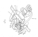
- a miter saw 100 comprises a base, a worktable 2 for supporting workpieces 200 to be cut, a first support member 4 attached to the worktable 2, a second support member 5 attached to the first support member 4, and a saw unit 3 attached to the second support member 5.
- the saw unit 3 is pivotally connected to the second support member 5 via a pivot 6, such that the saw unit 3 can be pivoted up and down relative to the base 1 to cut the workpieces vertically.
- the first support member 4 defines a longitudinal axis 41, the first support member 4 is pivotable clockwise and anticlockwise to incline to a determined angle relative to the worktable 2 to cut the workpieces.
- a lock mechanism disposed between the first support member 4 and the worktable 2 locks the first support member 4 on the worktable 2.
- the first support member 4 and the second support member 5 are all made of iron-based materials, such as cast iron, ferroalloy. Iron-based materials are used to increase Rigidities and make costs lower.
- the worktable 2 has a front side 22 closing with an operator and a rear side 23 disposed oppositely, the worktable 2 is rotatably mounted on the base 1.
- a cutting groove is disposed on the worktable 2 parallel to the longitudinal axis 41;
- a fence 24 is disposed on the worktable 2 to locate the workpieces 200, the fence 24 is perpendicular to the longitudinal axis 41;
- a anti-falling support rack 25 disposed on the worktable 2 is parallel to a direction of the longitudinal axis 41.
- the saw unit comprises a blade 31, a blade shaft 32, a motor 33, a fixed guard 35 and a movable guard(not shown in FIGS),
- the blade 31 is mounted on the blade shaft 32 and is pivotable about the blade shaft 32; the blade shaft 32 is driven by the motor 33; a handle 36 and a carrying handle 37 are provided on the saw unit 3, the operator grasps the handle 36 to make the saw unit 3 to cut the workpieces, a first switch(not shown in FigS) is provided on the handle 36.
- the first switch is used to start and turnoff the motor 33; the carrying handle 37 is used for transporting the miter saw 100 expediently; the fixed guard 35 is generally fixed to the motor 33 for covering a part of the blade 31; the moveable guard is pivoted on the fixed guard 35 for covering a spare of the blade 31 with the blade 31 in a noncutting position. the movable guard is pivoted relative to the fixed guard 35 to expose the blade 31 to cut the workpieces.
- a moveable guard driven mechanism is connected to the moveable guard for opening and closing the moveable guard quickly.
- the fixed guard 35 is connected to the second support member via a pivot 6, thus the handle 36 can be operated to make the saw unit 3 to perform cutting operation.
- a matching mechanism 7 is disposed between the first support member 4 and the second support member 5, the matching mechanism 7 is operated to cause the second support member 5 to move with respect to the first support member 4 frontward or backward along a direction of the longitudinal axis.
- the cutting operation is performed when the second support member 5 is moved to a plurality of predetermined working positions, but the cutting operation isn't performed when the second support member 5 is in the moving process.
- the predetermined working positions should be predetermined, and the predetermined working positions are corresponding to the admissible maximal specifications of workpieces to be cut .
- the admissible maximal specifications of workpieces to be cut comprises a admissible maximal size of the workpieces to be cut in the direction parallel to the longitudinal axis, that is the workpieces' width, or a admissible maximal size of the workpieces to be cut in the direction perpendicular to the longitudinal axis, that is the workpieces' height.
- the matching mechanism 7 comprises a guide groove 71 disposed on the first support member 4 extending along the direction of longitudinal axis 41, and a guide block72 disposed on the second support member 5 for connecting with the guide groove 71.
- the guide groove can also be disposed on the second support member 5, the guide block connected with the guide groove is disposed on the first support member 4 o
- the second support member 5 is movable frontward or backward with respect to the first support member along the direction of the longitudinal axis 41, the longitudinal axis 41 is perpendicular to the pivot 6.
- the guide block 72 and the second support member 5 are integratly formed.
- the guide block 72 and the second support member 4 are also integrally formed.
- the second support member 5 can be slidable with respect to the first support member 4, while other intermedium need not used. So the miter saw has a compact structure and a lower cost. The miter saw slides during the predetermined working positions, and doesn't frequently slide. Thus the abrasion between the guide block 72 and the guide groove 71 is reduced. Of course, to reduce the abrasion, a friction pad is disposed between the guide groove 71 and the guide block 72.
- the guide groove 71 is a swallow-tailed groove.
- the guide groove 71 is also other shape engaged groove like T-groove or V-groove.
- the miter saw 100 comprises a indicating mechanism 8 for indicating the predetermined working positions.
- the indicating mechanism 8 comprises working position signs 81 disposed on the first support member 4 and indicating signs 82 disposed on the second support member 5, the indicating signs 82 are corresponding to the working position signs 81 when the second support member 5 is moved to the corresponding work position.
- the indicating signs 82 are facing to the working position signs 81 in a direction perpendicular to the longitudinal axis.
- the working position signs are also disposed on the second support member 5, while the indicating signs 82 attached to the working position signs are disposed on the first support member 4.
- the indicating sign 82 is best aligned with the pivot 6 in the direction perpendicular to the longitudinal axis 41.
- the plurality of predetermined working positions are arranged ordinally in the direction parallel to the longitudinal axis 41.
- the miter saw has three working positions. Of course, more or less cutting positions should be provided according to the design requirement.
- the working position signs 81 comprise a first working position sign 811, a second working position sign 812 and a third working position sign 813. Of course, it is best to make the maximal specifications of workpieces to be cut as the working position signs 81.
- the indicating sign 82 is exactly facing to the first working position sign 811 in a first work position, now the maximal specifications of the workpieces to be cut is max width 6inches with max height 2inches, or max width 4inches with max height 4inches. That is to say, in the first work position, the miter saw can completely cut the workpieces which is smaller than the maximal specifications of workpieces to be cut .
- the workpieces are smaller or equal to 6inches in the direction parallel to the longitudinal axis, and smaller or equal to 2inches in the direction perpendicular to the longitudinal axis.
- the admissive maximal specifications of workpieces to be cut are 6*4inches, actual cutting size may be attained 6.5*4.5 inches.
- the miter saw can cut some workpieces at the same time. The sizes of being added of some workpieces are in the maximal cutting range.
- the indicating sign 82 is exactly facing to the second working position sign 812 in a second work position, now the maximal specifications of the workpieces to be cut is max width 6inches with max height 4inches. That is to say, in the second work position, the miter saw can completely cut the workpieces which is smaller than maximal specifications of the workpieces to be cut.
- the indicating sign 82 is exactly facing to the third working position sign 812 in a third work position, now the maximal specifications of the workpieces to be cut is max width 8inches with max height 2inches. That is to say, in the third work position, the miter saw can completely cut the workpieces which is smaller than maximal specifications of the workpieces to be cut.
- a matching mechanism 7 is disposed between the first support member 4 and the second support member 5, the matching mechanism 7 can cause the second support member 5 to move with respect to the first support member 4 along the direction of the longitudinal axis 41, and the cutting operation is performed in the plurality of predetermined working positions. So the cutting capacity is increased, the miter saw can cut workpieces with more specifications.
- the miter saw has a compact structure and a lower cost.
- the miter saw 100 further comprises a positioning mechanism 9 for determining the position of the second support member 5 at the corresponding predetermined working positions with respect to the first support member 4..
- the positioning mechanism 9 comprises a first receiving groove91, second receiving groove 92 and third receiving groove 93 being corresponding to the three predetermined working positions disposed on the first support member 4; a stop member(not shown in Figs) is disposed on the second support member 5 to attached with the first receiving groove91, second receiving groove 92 and third receiving groove 93; a spring(not shown in Figs) is disposed in the second support member 5, the spring and the stop member are all received in a stop groove 94 disposed on the second support member.
- the spring urges the stop member always toward the attached direction to the first receiving groove91, second receiving groove 92 and third receiving groove 93.
- the stop member 94 is a steel ball. Because being pressed by the spring, a portion of the steel ball is exposed beyond the surface of the second support member. So the steel ball is attached with corresponding receiving groove to perform reliable stop at the working positions.
- the stop member In the first work position, the stop member is attached with the first receiving groove 91 to surely position the second support member 5 at the first work position. As such, In the second working position, third working position, the stop member is respectively attached with the second, third receiving grooves 92,93 to surely position the second support member 5 at the second working position, third working position.
- the second support member 5 is positioned at the corresponding working positions with respect to the first support member 4.
- the positioning mechanism can also be other mode.
- a stop groove is attached with a stop pin to position the second support member 5 at the corresponding working positions with respect to the first support member 4.
- the miter saw further comprises a lock device to lock the second support member 5 at the corresponding working positions with respect to the first support member 4, so the cutting precision is made sure.
- the lock device 10 comprises a thread hole 11 disposed on the second support member 5, a lock member 12 attached with the thread hole 11, and a contact surface 43 attached with the lock member 12.
- the contact surface 43 is disposed on the first support member 4.
- the second support member 5 is also locked at the corresponding working positions with respect to the first support member 4.
- the lock device is electromagnetism lock.
- a winding is disposed on the one of the second support member 5 and the first support member 4
- a winding or a permanent magnet is disposed on the other one of the second support member 5 and the first support member 4
- a second switch is disposed on the handle or where the operator operate expediently, the second switch is connected to the winding by a wire. So when the second switch is started, the winding connected to the second switch, and the other winding or the permanent magnet generate inverted magnetic field to lock the second support member 5 on the first support member 4. When the second switch is turned off, the winding connected to the second switch, and the other winding or the permanent magnet don't generate inverted magnetic field, thus, the second support member 5 is movable with respect to the first support member 4.
- the matching mechanism 7a comprises a guide groove 71 a disposed on the first support member 4, and a guide block 72a disposed on the second support member 5, a connected surface between the guided groove 71 a and the guided block 72a inclines relative to the direction of longitudinal axis 41, so the connected surface has a certain height difference.
- the connected surface may be not a plane, may also be a curve surface or other shape suface.
- the projections of the plurality of predetermined working positions are arranged ordinally in a direction of the longitudinal axis 41. That is to say, although a actual moved direction of the second support member with respect to the first support member isn't always parallel to the direction of the longitudinal axis, the actual moved direction has a subdivision in a direction of parallel to longitudinal axis.
- the second support member is movable frontward or backward with respect to the first support member by unslidable mode.
- a first, second and third receiving groove 91b,92b,93b disposed on the first support member 4b are corresponding to the three predetermined working positions;
- a stop pin 95b disposed on the second support member 5b is attached with the first, second and third receiving groove 91b,92b,93b;
- a pivotable lock member 12b is disposed on the second support member 5b,a first, second, third lock holes 13b,14b,15b attached with the lock member 12b are disposed on the first support member 4b.
- the lock member 12b is turned tight to attach to the first lock hole 13b when the stop pin 95b is attached to the first receiving groove 91b to surely lock the second support member 5b at the first work position.
- the lock member 12b is turned loose to disengage the first lock hole 13b, thus the second support member 5b is moved with respect to the first support member 4b.
- projections of the plurality of the predetermined working positions on the longitudinal axis are arranged ordinally.
Landscapes
- Engineering & Computer Science (AREA)
- Mechanical Engineering (AREA)
- Life Sciences & Earth Sciences (AREA)
- Wood Science & Technology (AREA)
- Forests & Forestry (AREA)
- Sawing (AREA)
Applications Claiming Priority (2)
| Application Number | Priority Date | Filing Date | Title |
|---|---|---|---|
| CN200810128593A CN101612674A (zh) | 2008-06-23 | 2008-06-23 | 斜断锯 |
| PCT/CN2009/071171 WO2009155800A1 (fr) | 2008-06-23 | 2009-04-07 | Scie à onglets |
Publications (2)
| Publication Number | Publication Date |
|---|---|
| EP2301700A1 true EP2301700A1 (fr) | 2011-03-30 |
| EP2301700A4 EP2301700A4 (fr) | 2013-10-30 |
Family
ID=41443996
Family Applications (1)
| Application Number | Title | Priority Date | Filing Date |
|---|---|---|---|
| EP09768725.5A Withdrawn EP2301700A4 (fr) | 2008-06-23 | 2009-04-07 | Scie à onglets |
Country Status (4)
| Country | Link |
|---|---|
| US (1) | US20110179925A1 (fr) |
| EP (1) | EP2301700A4 (fr) |
| CN (1) | CN101612674A (fr) |
| WO (1) | WO2009155800A1 (fr) |
Families Citing this family (8)
| Publication number | Priority date | Publication date | Assignee | Title |
|---|---|---|---|---|
| US8250956B2 (en) * | 2009-04-28 | 2012-08-28 | Robert Bosch Gmbh | Miter saw with work surface extensions |
| US8978530B2 (en) * | 2011-04-25 | 2015-03-17 | Key Technology, Inc. | Cutting apparatus employing a magnet |
| CN102756170B (zh) * | 2011-04-29 | 2015-03-11 | 苏州宝时得电动工具有限公司 | 斜断锯 |
| CN103008776A (zh) * | 2012-12-12 | 2013-04-03 | 浙江永康东立电机有限公司 | 一种动力斜断锯 |
| CN104511653B (zh) * | 2013-09-30 | 2017-10-17 | 苏州宝时得电动工具有限公司 | 切割机 |
| CN103692558A (zh) * | 2013-12-09 | 2014-04-02 | 山东交通学院 | 一种用于加速加载实验的试件专用切割机 |
| US10279497B2 (en) | 2016-07-27 | 2019-05-07 | Key Technology, Inc. | Cutting apparatus employing a magnet |
| CN114951793B (zh) * | 2022-04-25 | 2023-09-29 | 上海市建筑装饰工程集团有限公司 | 一种带有智能保护系统的型材切割装置及控制方法 |
Family Cites Families (19)
| Publication number | Priority date | Publication date | Assignee | Title |
|---|---|---|---|---|
| US3302669A (en) * | 1964-06-29 | 1967-02-07 | Edler Adolph | Motor powered radial arm tool support |
| US3498345A (en) * | 1967-08-30 | 1970-03-03 | Miter Associates Ltd | Simultaneously adjustable saw mount and mitering device |
| JPH0518082Y2 (fr) * | 1987-02-20 | 1993-05-14 | ||
| US5054352A (en) * | 1989-01-17 | 1991-10-08 | Makita Electric Wroks, Ltd. | Miter saw |
| US5257570A (en) * | 1990-07-16 | 1993-11-02 | Ryobi Limited | Circular saw unit |
| US5220857A (en) * | 1991-11-21 | 1993-06-22 | Freeburger Barron D | Miter saw apparatus |
| DE69313011T2 (de) * | 1992-05-22 | 1998-03-19 | Makita Corp | Gehrungssäge |
| US6886440B2 (en) * | 2002-09-19 | 2005-05-03 | Black & Decker Inc. | Slide miter saw |
| JP4254429B2 (ja) * | 2003-08-28 | 2009-04-15 | 日立工機株式会社 | 卓上スライド切断機 |
| JP2005279933A (ja) * | 2004-03-26 | 2005-10-13 | Hitachi Koki Co Ltd | 卓上切断機 |
| CN2684994Y (zh) * | 2004-03-29 | 2005-03-16 | 王骥 | 斜断锯切割行程调节装置 |
| AU2005205796B2 (en) * | 2004-09-02 | 2007-08-09 | Hitachi Koki Co., Ltd. | Miter saw |
| GB0503102D0 (en) * | 2005-02-15 | 2005-03-23 | Gmca Pty Ltd | Guide for cutting unit |
| US20060236834A1 (en) * | 2005-04-21 | 2006-10-26 | Nicholas Ange | Combination radial and miter saw |
| EP1738850A1 (fr) * | 2005-06-28 | 2007-01-03 | Positec Power Tools (Suzhou) Co., Ltd. | Table de machine-outil |
| CN2853251Y (zh) * | 2005-12-30 | 2007-01-03 | 苏州宝时得电动工具有限公司 | 斜断锯 |
| US20080276773A1 (en) * | 2006-03-30 | 2008-11-13 | Radhakrishna Shesha Iyengar Togare | Multipurpose cutting method for cutting various materials |
| US8025001B2 (en) * | 2007-01-09 | 2011-09-27 | Rexon Industrial Corp., Ltd. | Miter saw with support devices |
| CN201064845Y (zh) * | 2007-08-06 | 2008-05-28 | 江苏金飞达电动工具有限公司 | 具有调节定位装置的斜断锯 |
-
2008
- 2008-06-23 CN CN200810128593A patent/CN101612674A/zh active Pending
-
2009
- 2009-04-07 US US13/000,905 patent/US20110179925A1/en not_active Abandoned
- 2009-04-07 WO PCT/CN2009/071171 patent/WO2009155800A1/fr not_active Ceased
- 2009-04-07 EP EP09768725.5A patent/EP2301700A4/fr not_active Withdrawn
Also Published As
| Publication number | Publication date |
|---|---|
| EP2301700A4 (fr) | 2013-10-30 |
| CN101612674A (zh) | 2009-12-30 |
| WO2009155800A1 (fr) | 2009-12-30 |
| US20110179925A1 (en) | 2011-07-28 |
Similar Documents
| Publication | Publication Date | Title |
|---|---|---|
| EP2301700A1 (fr) | Scie à onglets | |
| CN102615345B (zh) | 切割机 | |
| US6986370B1 (en) | Table saw | |
| CA2713686C (fr) | Appareil de coupe a outil electrique | |
| US4276799A (en) | Power tool apparatus | |
| EP2581167B1 (fr) | Dispositifs de guidage pour outils électriques | |
| US6478664B2 (en) | Cut-off saw | |
| EP3141352B1 (fr) | Combinaison de table de travail et ensemble clôture et machine de coupe comportant une combinaison | |
| US7669510B2 (en) | Miter saw having holder fixing mechanism | |
| US9174288B2 (en) | Slidable miter saw with guiding mechanism | |
| US11351640B2 (en) | Cutting tool | |
| US20060201301A1 (en) | Cutting tool and parts and accessories therefor | |
| TWM446669U (zh) | 切割機 | |
| US7581477B2 (en) | Saw table and clamping mechanism therefor | |
| US20060201300A1 (en) | Cutting tool and parts and accessories therefor | |
| US9168598B2 (en) | Forward extending workpiece support | |
| US20070095186A1 (en) | Guide and portable cutting tool provided therewith | |
| TW201943480A (zh) | 用於桌鋸之非結合式擋板 | |
| CN110171034A (zh) | 具有两级台延伸系统的台锯 | |
| CN211053288U (zh) | 一种管道切割机的切面打磨装置 | |
| CN109465492B (zh) | 电锯 | |
| EP1818127A3 (fr) | Dispositif de blocage de l'angle d'onglet pour scie à onglet | |
| EP1514626B1 (fr) | Ensemble de guidage pour un outil motorisé et un outil motorisé comprenant un tel ensemble | |
| JP3136841U (ja) | スライドテーブルソー | |
| TWI441700B (zh) | 切斷機 |
Legal Events
| Date | Code | Title | Description |
|---|---|---|---|
| PUAI | Public reference made under article 153(3) epc to a published international application that has entered the european phase |
Free format text: ORIGINAL CODE: 0009012 |
|
| 17P | Request for examination filed |
Effective date: 20101222 |
|
| AK | Designated contracting states |
Kind code of ref document: A1 Designated state(s): AT BE BG CH CY CZ DE DK EE ES FI FR GB GR HR HU IE IS IT LI LT LU LV MC MK MT NL NO PL PT RO SE SI SK TR |
|
| AX | Request for extension of the european patent |
Extension state: AL BA RS |
|
| RIN1 | Information on inventor provided before grant (corrected) |
Inventor name: SZOMMER, HARRY Inventor name: GERHARDT, GRAHAM Inventor name: BROWN, WARREN |
|
| DAX | Request for extension of the european patent (deleted) | ||
| A4 | Supplementary search report drawn up and despatched |
Effective date: 20131002 |
|
| RIC1 | Information provided on ipc code assigned before grant |
Ipc: B23D 45/02 20060101AFI20130926BHEP Ipc: B23D 45/14 20060101ALI20130926BHEP Ipc: B27B 5/20 20060101ALI20130926BHEP Ipc: B23D 47/04 20060101ALI20130926BHEP |
|
| STAA | Information on the status of an ep patent application or granted ep patent |
Free format text: STATUS: THE APPLICATION IS DEEMED TO BE WITHDRAWN |
|
| 18D | Application deemed to be withdrawn |
Effective date: 20140429 |