EP2301704A2 - Chalumeau de soudage manuel - Google Patents
Chalumeau de soudage manuel Download PDFInfo
- Publication number
- EP2301704A2 EP2301704A2 EP10174324A EP10174324A EP2301704A2 EP 2301704 A2 EP2301704 A2 EP 2301704A2 EP 10174324 A EP10174324 A EP 10174324A EP 10174324 A EP10174324 A EP 10174324A EP 2301704 A2 EP2301704 A2 EP 2301704A2
- Authority
- EP
- European Patent Office
- Prior art keywords
- switching element
- welding torch
- switching
- manual welding
- torch according
- Prior art date
- Legal status (The legal status is an assumption and is not a legal conclusion. Google has not performed a legal analysis and makes no representation as to the accuracy of the status listed.)
- Granted
Links
Images
Classifications
-
- B—PERFORMING OPERATIONS; TRANSPORTING
- B23—MACHINE TOOLS; METAL-WORKING NOT OTHERWISE PROVIDED FOR
- B23K—SOLDERING OR UNSOLDERING; WELDING; CLADDING OR PLATING BY SOLDERING OR WELDING; CUTTING BY APPLYING HEAT LOCALLY, e.g. FLAME CUTTING; WORKING BY LASER BEAM
- B23K9/00—Arc welding or cutting
- B23K9/32—Accessories
-
- B—PERFORMING OPERATIONS; TRANSPORTING
- B23—MACHINE TOOLS; METAL-WORKING NOT OTHERWISE PROVIDED FOR
- B23K—SOLDERING OR UNSOLDERING; WELDING; CLADDING OR PLATING BY SOLDERING OR WELDING; CUTTING BY APPLYING HEAT LOCALLY, e.g. FLAME CUTTING; WORKING BY LASER BEAM
- B23K9/00—Arc welding or cutting
- B23K9/10—Other electric circuits therefor; Protective circuits; Remote controls
- B23K9/1087—Arc welding using remote control
-
- B—PERFORMING OPERATIONS; TRANSPORTING
- B23—MACHINE TOOLS; METAL-WORKING NOT OTHERWISE PROVIDED FOR
- B23K—SOLDERING OR UNSOLDERING; WELDING; CLADDING OR PLATING BY SOLDERING OR WELDING; CUTTING BY APPLYING HEAT LOCALLY, e.g. FLAME CUTTING; WORKING BY LASER BEAM
- B23K9/00—Arc welding or cutting
- B23K9/24—Features related to electrodes
- B23K9/28—Supporting devices for electrodes
- B23K9/287—Supporting devices for electrode holders
Definitions
- the invention relates to a manual welding torch with a switching device, wherein the switching device is formed of a switching element and actuators, wherein the switching element is movably mounted relative to the actuators, and wherein by means of the switching element, the actuators are actuated.
- Manual welding torches regularly have switching devices which are integrated in one handle.
- the switching devices essentially serve to trigger a welding operation with, for example, a wire feed.
- further switching devices in the manner of a remote control or a remote control module for controlling welding machine parameters such as wire feed speed, welding power, arc length, etc. may be integrated.
- welding machine parameters such as wire feed speed, welding power, arc length, etc.
- the known from the prior art switching devices for adjusting a welding machine can be designed, inter alia, as a double button, as a two- or four-way rocker, as a cross-type rocker or as a rotary switch with potentiometer.
- an on / off button for actuating the welding function of the welding machine can be integrated on an upper side of a handle, a switching device or remote control and in addition to an underside of the handle.
- An operation of the switching device or the remote control on the handle is usually at the bottom of the handle with the index finger and at the top by means of the thumb.
- a disadvantage of the operation of the known switching devices that the operation must be done by means of usually thick welding gloves, which often causes incorrect operation. This is due in particular to the fact that the known buttons are made relatively small due to the limited space available on the handle and more than two switching states are adjustable on a button.
- a use of multiple shift paddles is disadvantageous since here must be done for a change between the shift paddles lifting and grasping the thumb without an operator during a welding process can look at the handle. This can for example have a simultaneous triggering of two shift paddles of the switching device result.
- stability of known switching devices is limited since mechanical stresses such as e.g. Impacts act directly on the trained as actuators button.
- the present invention is therefore based on the object to propose a manual welding torch, which has over the hand welding torches known from the prior art over an improved operation.
- the manual welding torch comprises a switching device, wherein the switching device is formed of a switching element and actuators, wherein the switching element is movably mounted relative to the actuators, wherein by means of the switching element, the actuators are actuated, and wherein the switching element is movable in at least two degrees of freedom.
- the invention is based on the idea of providing a switching device on a handle of the manual welding torch which has a switching element which is separate from a plurality of actuators. Further, the switching element is movable in at least two degrees of freedom, so that the actuators can be operated independently of each other alone with the one switching element.
- An otherwise error-prone operation of, for example, a double rocker, formed of two juxtaposed switching elements, is substantially improved by the use of the individual switching element in the invention.
- a conversion of a control finger or a grasping a hand is no longer necessary.
- the switching element is movable in at least two degrees of freedom, the function of a double rocker can also be filled with the individual switching element.
- the actuators are separated from the switching element, so that when an external damage of the switching element, for example by dropping the manual welding torch, the actuators are not necessarily damaged.
- the switching element may be movable in translational degrees of freedom. That a switching operation can be triggered by a sliding or tilting movement of the switching element along a linear path.
- the switching element can be translationally movable in several directions, for example along a longitudinal axis of the manual welding torch and transversely thereto.
- the switching element may be movable in rotational degrees of freedom. Accordingly, the switching element for performing a Switching or adjusting operation to be rotatable about a longitudinal axis of the switching element. In this case, the switching element can be rotated by only a few degrees or by several turns. It is also conceivable that the switching element in addition to the rotational mobility is also translationally movable.
- the switching device is particularly easy to form, if this comprises a housing, wherein the switching element can then be movably mounted relative to the housing.
- the switching device can be easily provided with a connecting line, so that the housing of the switching device is easily adaptable to a handle of the manual welding torch.
- a handle of the manual welding torch For example, an existing handle provided with a switching device or in a designated recess on a handle, the housing of the switching device can be used.
- the switching device can then be formed independently of the manual welding torch, whereby the switching device is particularly easy to manufacture and interchangeable with the manual welding torch.
- the housing can form a slotted guide for the switching element.
- a simultaneous actuation of more than one actuator can be prevented by such a trained leadership of the switching element in the slotted guide.
- the slotted guide can be designed so that a selection of a movement direction of the switching element is made possible only in an actuation-free neutral position of the switching element.
- the link guide may be formed, for example, as a cross-shaped through opening in the housing, within which the switching element is movable and in the center of which the neutral position is provided.
- the switching element may have an operating knob for manual handling.
- the actuating button for example, can be comparatively large compared to a double rocker, so that it easily moves with a welder's glove can be.
- the actuating knob is round.
- the housing may be formed so that it at least partially surrounds the actuating button along its lateral circumference.
- the actuating button can be countersunk in a recess or depression formed in the housing, so that the actuating button protrudes only slightly beyond the housing in the dimensions required for actuation.
- an actuator may be formed as an electromechanical switch.
- the electromechanical switch in its simplest form, can be a button or an on / off switch which can transmit a switching pulse to a welding machine.
- the electromechanical switch may for example be arranged separately from the switching element, and be actuated by this by means of a mechanical contact.
- an actuator may be formed as an opto-electrical switch.
- an electromechanical switch In contrast to an electromechanical switch, a switching operation without mechanical contact with the switching element can be triggered in the opto-electrical switch. Since opto-electrical switches have no mechanically moving components, these switches are particularly durable.
- an actuator may be formed as a Weg messengerdes element.
- a distance-measuring element may for example be a linear or rotary potentiometer, a rotary encoder or simply a scale of be sensory detectable division. Such, weg messengerdes element allows, for example, a continuous adjustment of an operating parameter.
- the switching device may have at least four actuators.
- the four actuators can be arranged so that they can be operated in two directions of movement of the switching element. In a simplest embodiment, this may be, for example, a movement of the switching element between a switching position front / rear and a switching position right / left.
- the four actuators can be easily arranged on a circuit board. Of course, further actuators can be provided, which are usable in the context of other directions of movement.
- an actuation of the actuators can then be further simplified in that the switching element has a switching ring.
- the actuators can then also be arranged in a circle in the region of the switching ring, which can form a circular contact surface for the actuators. Tilting of the switching ring relative to the actuators in the direction of one of the actuators then causes its actuation.
- the switching ring it is irrelevant how many actuators are arranged in the region of the switching ring.
- the switching device may have at least one stop. This can be prevented in an advantageous manner that the actuators, for example, by an accidental impact on the switching element, be damaged as a result of large force.
- the housing or a sliding guide of the housing may be formed so that the housing forms the stop for the switching element.
- the stop may also be formed by other components which are suitable to limit a movement of the switching element.
- the switching element when the switching element is movably mounted by means of a spherical cap of the switching element in a bearing device of the switching device is particularly advantageous.
- the switching element is then in the context of a circular path, which is defined by a spherical surface of the spherical cap, arbitrarily movable. It is also possible to turn the switching element about its own axis. Compared with a linear guide or a rocker, such a bearing device therefore enables the use of a large number of possible directions of movement with a single bearing.
- the bearing device has a spring element which can bring about a return of the switching element in an actuation-free neutral position. That is, the switching element can then be automatically moved back to an initial position after an actuation of the switching element by an operator.
- the neutral position can be chosen so that no actuators are actuated by the switching element.
- a spring force of the spring element can be selected or the spring element can be made adjustable so that a desired actuation force of the switching element for switching the actuators must be applied.
- a spring element a coil spring or compression spring can be used as a spring element.
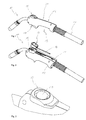
- FIG. 1 to 2 1 shows a manual welding torch 10 with a handle 13 formed from grip shells 11 and 12 and a switching device 15 arranged in a recess 14 formed between the grip shells 11 and 12.
- the switching device 15 is inserted into the recess 14 so far that a connecting line 16 of the switching device 15 extends within the handle 13.
- the connecting line 16 is used for signal transmission to a control not shown here in detail also here not fully illustrated welding machine.
- the connection line 16 is guided along a supply hose 17.
- a switching device designed as a toggle switch 18 is arranged on the handle 13, which serves to trigger a welding function.
- the toggle switch 18 is arranged on an underside 19 of the handle 13 and is preferably operated with an index finger and the switching device 15 is arranged on an upper side 20 of the handle 13 and is preferably operated with a thumb.
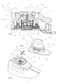
- the switching device 15 is formed of a switching element 21, a housing 22 and arranged on a printed circuit board 23 actuators 24, 25 and 26. Another, fourth actuator is also present, but not apparent from the illustrations.
- the switching element 21 is in turn formed from an operating knob 27, a spherical cap 28 with a screw fastening 29 for the actuating knob 27 and a switching ring 30.
- the spherical cap 28 is mounted movably on all sides in a ball socket 31 of a bearing device 32 designed in this way, wherein a compression spring 33 is arranged between the ball socket 31 and the switching ring 30 and brings about a return of the switching element 21 into a neutral position shown here.
- the ball socket 31 is firmly fixed by means of a screw 34 to the circuit board 23.
- the thus formed bearing device 32 now allows tilting or movement of the switching element 21 relative to a longitudinal axis 35 of the switching element 21. In this case reaches a contact surface 36 of the switching ring 30 on a switching contact 37 of the actuators 24, 25 or 26 or not visible actuator.
- a recess 39 is formed within which the actuating knob 27 is movably arranged.
- the recess 39 is formed so that the operating knob 27 only slightly surmounted a peripheral edge 40 of the housing 22 and is thus protected by the peripheral edge 40 from damage.
- a passage opening 41 is formed within the recess 39, which in turn forms a slide guide 42 for the actuating knob 27.
- An inner contour 43 of the passage opening 41 is accordingly designed such that material recesses 46, 47, 48 and 49 are provided in the direction of actuation axes 44 and 45 shown here with arrows.
- the housing 22 is formed so that the housing 22 can be closed with the circuit board 23 and the through hole 41 can be completely covered by the operation knob 27 regardless of an operation thereof, so that the switching device 15 forms a self-contained assembly 50 which can be inserted into the handle 13 via the connecting line 16, which is contacted on the printed circuit board 23.
Landscapes
- Engineering & Computer Science (AREA)
- Physics & Mathematics (AREA)
- Plasma & Fusion (AREA)
- Mechanical Engineering (AREA)
- Arc Welding Control (AREA)
- Arc Welding In General (AREA)
- Mechanical Control Devices (AREA)
Priority Applications (1)
| Application Number | Priority Date | Filing Date | Title |
|---|---|---|---|
| US12/880,508 US20110062131A1 (en) | 2009-09-11 | 2010-09-13 | Hand welding torch |
Applications Claiming Priority (1)
| Application Number | Priority Date | Filing Date | Title |
|---|---|---|---|
| DE102009040907 | 2009-09-11 |
Publications (3)
| Publication Number | Publication Date |
|---|---|
| EP2301704A2 true EP2301704A2 (fr) | 2011-03-30 |
| EP2301704A3 EP2301704A3 (fr) | 2017-06-07 |
| EP2301704B1 EP2301704B1 (fr) | 2019-10-09 |
Family
ID=43413464
Family Applications (1)
| Application Number | Title | Priority Date | Filing Date |
|---|---|---|---|
| EP10174324.3A Active EP2301704B1 (fr) | 2009-09-11 | 2010-08-27 | Chalumeau de soudage manuel |
Country Status (2)
| Country | Link |
|---|---|
| US (1) | US20110062131A1 (fr) |
| EP (1) | EP2301704B1 (fr) |
Cited By (3)
| Publication number | Priority date | Publication date | Assignee | Title |
|---|---|---|---|---|
| DE202017101708U1 (de) | 2017-03-23 | 2017-05-04 | Merkle Schweißanlagen-Technik GmbH | Schweißbrenner und Schweißgerät hierfür |
| DE202021104755U1 (de) | 2021-09-03 | 2021-10-04 | Alexander Binzel Schweisstechnik Gmbh & Co. Kg | Halterung mit einem Fixiermittel zur lösbaren Fixierung eines Handbrenners und einen Handbrenner mit einer Halterung |
| DE102021122844A1 (de) | 2021-09-03 | 2023-03-09 | Alexander Binzel Schweisstechnik Gmbh & Co. Kg | Halterung mit einem Fixiermittel zur lösbaren Fixierung eines Handbrenners und Handbrenner mit einer Halterung |
Families Citing this family (25)
| Publication number | Priority date | Publication date | Assignee | Title |
|---|---|---|---|---|
| GB2496686A (en) * | 2011-11-21 | 2013-05-22 | Uniarc Ltd | Remote control apparatus for a welding machine |
| USD735002S1 (en) * | 2012-03-20 | 2015-07-28 | Illinois Tool Works Inc. | Welding torch handle with curved appearance |
| US9550250B2 (en) * | 2012-11-26 | 2017-01-24 | Howard T. Upton | Torch-mounted fingertip welding controller |
| USD771727S1 (en) * | 2014-08-05 | 2016-11-15 | Trafimet S.P.A. | Torch |
| US10799972B2 (en) * | 2014-11-10 | 2020-10-13 | Illinois Tool Works Inc. | System for controlling welding parameter of a welding system |
| USD837848S1 (en) | 2015-07-19 | 2019-01-08 | Dan A. Murphy | Oxygen acetylene torch cutting handle with flush mount trigger |
| USD806152S1 (en) * | 2016-03-18 | 2017-12-26 | Magna Industries, Inc. | Torch |
| TWD180598S (zh) * | 2016-07-14 | 2017-01-11 | 蔡進琳 | 瓦斯燃燒器(五)之部分 |
| USD806770S1 (en) * | 2016-07-19 | 2018-01-02 | Dan A. Murphy | Oxygen acetylene torch handle |
| USD813627S1 (en) * | 2016-12-12 | 2018-03-27 | Chin-Lin Tsai | Gas torch |
| USD888529S1 (en) | 2017-09-14 | 2020-06-30 | Tbi Industries Gmbh | Tool handle |
| USD869526S1 (en) * | 2017-10-12 | 2019-12-10 | NINE HKG Limited | Torch |
| USD852856S1 (en) * | 2017-11-08 | 2019-07-02 | Anvil International, Llc | Weld outlet |
| USD882361S1 (en) * | 2018-10-31 | 2020-04-28 | Lincoln Global, Inc. | Welding torch |
| USD883055S1 (en) * | 2018-10-31 | 2020-05-05 | Lincoln Global, Inc. | Welding torch |
| USD881664S1 (en) * | 2018-10-31 | 2020-04-21 | Lincoln Global, Inc. | Welding torch |
| USD893967S1 (en) | 2018-10-31 | 2020-08-25 | Lincoln Global, Inc. | Welding torch |
| US11047714B2 (en) | 2019-05-23 | 2021-06-29 | Worthington Cylinders Corporation | Methods and systems for a wireless monitoring system for a tank |
| USD904146S1 (en) * | 2019-07-25 | 2020-12-08 | Fronius International Gmbh | Welding torch |
| USD932857S1 (en) * | 2020-03-09 | 2021-10-12 | Worthington Cylinders Corporation | Hand torch |
| USD969580S1 (en) * | 2021-01-12 | 2022-11-15 | Jonathan Evans | Ergonomic welding handle |
| USD962029S1 (en) * | 2021-01-28 | 2022-08-30 | Lincoln Global, Inc. | Welding torch handle |
| USD962028S1 (en) * | 2021-01-28 | 2022-08-30 | Lincoln Global, Inc. | Welding torch handle |
| USD1017358S1 (en) * | 2021-11-03 | 2024-03-12 | Worthington Torch, Llc | Hand torch |
| USD1032314S1 (en) | 2022-07-28 | 2024-06-25 | Fronius International Gmbh | Handle for a welding torch |
Family Cites Families (9)
| Publication number | Priority date | Publication date | Assignee | Title |
|---|---|---|---|---|
| JPH0447616A (ja) * | 1990-06-11 | 1992-02-17 | Fujitsu Ltd | スイッチ素子 |
| FI974U1 (fi) * | 1993-06-15 | 1993-10-25 | Kemppi Oy | Handtagsreglerdon foer en TIG-braennare |
| US6051808A (en) * | 1998-02-04 | 2000-04-18 | C-K Worldwide Inc. | Welding torch with integral control |
| US6443973B1 (en) * | 1999-06-02 | 2002-09-03 | Power Medical Interventions, Inc. | Electromechanical driver device for use with anastomosing, stapling, and resecting instruments |
| CN1692401B (zh) * | 2002-04-12 | 2011-11-16 | 雷斯里·R·奥柏梅尔 | 多轴输入转换器装置和摇杆 |
| US6979799B2 (en) * | 2002-07-31 | 2005-12-27 | Illinois Tool Works Inc. | System and method for operating and locking a trigger of a welding gun |
| JP5001536B2 (ja) * | 2005-07-19 | 2012-08-15 | 株式会社ダイヘン | アーク溶接トーチ |
| US7594548B1 (en) * | 2006-07-26 | 2009-09-29 | Black & Decker Inc. | Power tool having a joystick control |
| US7652216B2 (en) * | 2007-12-18 | 2010-01-26 | Streamlight, Inc. | Electrical switch, as for controlling a flashlight |
-
2010
- 2010-08-27 EP EP10174324.3A patent/EP2301704B1/fr active Active
- 2010-09-13 US US12/880,508 patent/US20110062131A1/en not_active Abandoned
Non-Patent Citations (1)
| Title |
|---|
| None |
Cited By (5)
| Publication number | Priority date | Publication date | Assignee | Title |
|---|---|---|---|---|
| DE202017101708U1 (de) | 2017-03-23 | 2017-05-04 | Merkle Schweißanlagen-Technik GmbH | Schweißbrenner und Schweißgerät hierfür |
| DE202021104755U1 (de) | 2021-09-03 | 2021-10-04 | Alexander Binzel Schweisstechnik Gmbh & Co. Kg | Halterung mit einem Fixiermittel zur lösbaren Fixierung eines Handbrenners und einen Handbrenner mit einer Halterung |
| DE102021122844A1 (de) | 2021-09-03 | 2023-03-09 | Alexander Binzel Schweisstechnik Gmbh & Co. Kg | Halterung mit einem Fixiermittel zur lösbaren Fixierung eines Handbrenners und Handbrenner mit einer Halterung |
| WO2023031174A1 (fr) | 2021-09-03 | 2023-03-09 | Alexander Binzel Schweisstechnik Gmbh & Co. Kg | Support doté d'un moyen de fixation permettant la fixation libérable d'une torche manuelle et torche manuelle munie d'un support |
| DE102021122844B4 (de) | 2021-09-03 | 2024-08-22 | Alexander Binzel Schweisstechnik Gmbh & Co. Kg | Halterung mit einem Fixiermittel zur lösbaren Fixierung eines Handbrenners und Handbrenner mit einer Halterung |
Also Published As
| Publication number | Publication date |
|---|---|
| EP2301704B1 (fr) | 2019-10-09 |
| EP2301704A3 (fr) | 2017-06-07 |
| US20110062131A1 (en) | 2011-03-17 |
Similar Documents
| Publication | Publication Date | Title |
|---|---|---|
| EP2301704B1 (fr) | Chalumeau de soudage manuel | |
| DE102014112982A1 (de) | Elektrischer Schalter | |
| DE2937140A1 (de) | Schalter fuer die getriebehydraulik einer fahrbaren arbeitsmaschine | |
| DE102017110492A1 (de) | Armlehne, insbesondere für einen Bürostuhl | |
| DE10331130A1 (de) | Schalter für die Handbetätigung von Hebezeugen | |
| DE102016224417A1 (de) | Einspannvorrichtung zm Einspannen eines Werkstücks | |
| DE60109457T2 (de) | Vorrichtung für eine sequentielle kraftfahrzeuggetriebebedienung mit handgeschaltetem wählen und einlegen der gänge | |
| DE3329673A1 (de) | Schalteranordnung | |
| DE102017123163B4 (de) | Bedienvorrichtung zum Steuern eines Werkzeuges oder einer Arbeitsmaschine | |
| EP2949428A2 (fr) | Outil électrique, en particulier visseuse, doté d'un inverseur de sens de la marche | |
| DE102017110472B4 (de) | Joystick zum Steuern von Fahrzeug-, Maschinen- oder Anlagenfunktionen | |
| DE102007014745B4 (de) | Elektrische Schalteinrichtung für ein Kraftfahrzeug | |
| EP0050203A2 (fr) | Levier de réglage, notamment pour la présélection de la vitesse de déplacement dans des machines agricoles autopropulsées | |
| DE4300313C1 (de) | Drehantrieb für kipphebelbetätigte Schaltgeräte und Verwendung hierfür | |
| DE10040713B4 (de) | Elektrischer Schalter | |
| DE3117414C2 (de) | Steuergeber | |
| DE102016117785A1 (de) | Elektrischer Schalter | |
| EP3222135B1 (fr) | Taille haie avec gachette a force de maintien reduite | |
| DE4412557C2 (de) | Schaltgerät für Handbetätigung und die Umwandlung eines Betätigungsweges in ein elektrisches Signal | |
| DE202011051097U1 (de) | Heckenschere und Schaltervorrichtung davon | |
| DE60011786T2 (de) | Betätigungsvorrichtung für Arbeitsfahrzeuge | |
| EP1463376B1 (fr) | Elément de commande pour des appareils auditifs et des prothèses auditives | |
| DE3006405A1 (de) | Elektrisch betriebenes handgeraet | |
| DE2260882C3 (de) | Vorrichtung zum Steuern einer Honmaschine | |
| EP0275913B1 (fr) | Dispositif de commutation électrique |
Legal Events
| Date | Code | Title | Description |
|---|---|---|---|
| PUAI | Public reference made under article 153(3) epc to a published international application that has entered the european phase |
Free format text: ORIGINAL CODE: 0009012 |
|
| AK | Designated contracting states |
Kind code of ref document: A2 Designated state(s): AL AT BE BG CH CY CZ DE DK EE ES FI FR GB GR HR HU IE IS IT LI LT LU LV MC MK MT NL NO PL PT RO SE SI SK SM TR |
|
| AX | Request for extension of the european patent |
Extension state: BA ME RS |
|
| PUAL | Search report despatched |
Free format text: ORIGINAL CODE: 0009013 |
|
| AK | Designated contracting states |
Kind code of ref document: A3 Designated state(s): AL AT BE BG CH CY CZ DE DK EE ES FI FR GB GR HR HU IE IS IT LI LT LU LV MC MK MT NL NO PL PT RO SE SI SK SM TR |
|
| AX | Request for extension of the european patent |
Extension state: BA ME RS |
|
| RIC1 | Information provided on ipc code assigned before grant |
Ipc: B23K 9/28 20060101ALI20170502BHEP Ipc: B23K 9/10 20060101AFI20170502BHEP Ipc: B23K 9/32 20060101ALI20170502BHEP |
|
| PUAL | Search report despatched |
Free format text: ORIGINAL CODE: 0009013 |
|
| STAA | Information on the status of an ep patent application or granted ep patent |
Free format text: STATUS: REQUEST FOR EXAMINATION WAS MADE |
|
| 17P | Request for examination filed |
Effective date: 20171018 |
|
| RBV | Designated contracting states (corrected) |
Designated state(s): AL AT BE BG CH CY CZ DE DK EE ES FI FR GB GR HR HU IE IS IT LI LT LU LV MC MK MT NL NO PL PT RO SE SI SK SM TR |
|
| RIC1 | Information provided on ipc code assigned before grant |
Ipc: B23K 9/10 20060101AFI20180322BHEP Ipc: B23K 9/28 20060101ALI20180322BHEP Ipc: B23K 9/32 20060101ALI20180322BHEP |
|
| STAA | Information on the status of an ep patent application or granted ep patent |
Free format text: STATUS: EXAMINATION IS IN PROGRESS |
|
| 17Q | First examination report despatched |
Effective date: 20180430 |
|
| GRAP | Despatch of communication of intention to grant a patent |
Free format text: ORIGINAL CODE: EPIDOSNIGR1 |
|
| STAA | Information on the status of an ep patent application or granted ep patent |
Free format text: STATUS: GRANT OF PATENT IS INTENDED |
|
| INTG | Intention to grant announced |
Effective date: 20190410 |
|
| GRAS | Grant fee paid |
Free format text: ORIGINAL CODE: EPIDOSNIGR3 |
|
| GRAA | (expected) grant |
Free format text: ORIGINAL CODE: 0009210 |
|
| STAA | Information on the status of an ep patent application or granted ep patent |
Free format text: STATUS: THE PATENT HAS BEEN GRANTED |
|
| RAP1 | Party data changed (applicant data changed or rights of an application transferred) |
Owner name: TBI INDUSTRIES GMBH |
|
| AK | Designated contracting states |
Kind code of ref document: B1 Designated state(s): AL AT BE BG CH CY CZ DE DK EE ES FI FR GB GR HR HU IE IS IT LI LT LU LV MC MK MT NL NO PL PT RO SE SI SK SM TR |
|
| REG | Reference to a national code |
Ref country code: GB Ref legal event code: FG4D Free format text: NOT ENGLISH |
|
| REG | Reference to a national code |
Ref country code: CH Ref legal event code: EP |
|
| REG | Reference to a national code |
Ref country code: IE Ref legal event code: FG4D Free format text: LANGUAGE OF EP DOCUMENT: GERMAN |
|
| REG | Reference to a national code |
Ref country code: DE Ref legal event code: R096 Ref document number: 502010016296 Country of ref document: DE |
|
| REG | Reference to a national code |
Ref country code: AT Ref legal event code: REF Ref document number: 1188210 Country of ref document: AT Kind code of ref document: T Effective date: 20191115 |
|
| REG | Reference to a national code |
Ref country code: NL Ref legal event code: MP Effective date: 20191009 |
|
| REG | Reference to a national code |
Ref country code: LT Ref legal event code: MG4D |
|
| PG25 | Lapsed in a contracting state [announced via postgrant information from national office to epo] |
Ref country code: BG Free format text: LAPSE BECAUSE OF FAILURE TO SUBMIT A TRANSLATION OF THE DESCRIPTION OR TO PAY THE FEE WITHIN THE PRESCRIBED TIME-LIMIT Effective date: 20200109 Ref country code: FI Free format text: LAPSE BECAUSE OF FAILURE TO SUBMIT A TRANSLATION OF THE DESCRIPTION OR TO PAY THE FEE WITHIN THE PRESCRIBED TIME-LIMIT Effective date: 20191009 Ref country code: LT Free format text: LAPSE BECAUSE OF FAILURE TO SUBMIT A TRANSLATION OF THE DESCRIPTION OR TO PAY THE FEE WITHIN THE PRESCRIBED TIME-LIMIT Effective date: 20191009 Ref country code: NO Free format text: LAPSE BECAUSE OF FAILURE TO SUBMIT A TRANSLATION OF THE DESCRIPTION OR TO PAY THE FEE WITHIN THE PRESCRIBED TIME-LIMIT Effective date: 20200109 Ref country code: PL Free format text: LAPSE BECAUSE OF FAILURE TO SUBMIT A TRANSLATION OF THE DESCRIPTION OR TO PAY THE FEE WITHIN THE PRESCRIBED TIME-LIMIT Effective date: 20191009 Ref country code: PT Free format text: LAPSE BECAUSE OF FAILURE TO SUBMIT A TRANSLATION OF THE DESCRIPTION OR TO PAY THE FEE WITHIN THE PRESCRIBED TIME-LIMIT Effective date: 20200210 Ref country code: ES Free format text: LAPSE BECAUSE OF FAILURE TO SUBMIT A TRANSLATION OF THE DESCRIPTION OR TO PAY THE FEE WITHIN THE PRESCRIBED TIME-LIMIT Effective date: 20191009 Ref country code: LV Free format text: LAPSE BECAUSE OF FAILURE TO SUBMIT A TRANSLATION OF THE DESCRIPTION OR TO PAY THE FEE WITHIN THE PRESCRIBED TIME-LIMIT Effective date: 20191009 Ref country code: SE Free format text: LAPSE BECAUSE OF FAILURE TO SUBMIT A TRANSLATION OF THE DESCRIPTION OR TO PAY THE FEE WITHIN THE PRESCRIBED TIME-LIMIT Effective date: 20191009 Ref country code: NL Free format text: LAPSE BECAUSE OF FAILURE TO SUBMIT A TRANSLATION OF THE DESCRIPTION OR TO PAY THE FEE WITHIN THE PRESCRIBED TIME-LIMIT Effective date: 20191009 Ref country code: GR Free format text: LAPSE BECAUSE OF FAILURE TO SUBMIT A TRANSLATION OF THE DESCRIPTION OR TO PAY THE FEE WITHIN THE PRESCRIBED TIME-LIMIT Effective date: 20200110 |
|
| PG25 | Lapsed in a contracting state [announced via postgrant information from national office to epo] |
Ref country code: IS Free format text: LAPSE BECAUSE OF FAILURE TO SUBMIT A TRANSLATION OF THE DESCRIPTION OR TO PAY THE FEE WITHIN THE PRESCRIBED TIME-LIMIT Effective date: 20200224 Ref country code: HR Free format text: LAPSE BECAUSE OF FAILURE TO SUBMIT A TRANSLATION OF THE DESCRIPTION OR TO PAY THE FEE WITHIN THE PRESCRIBED TIME-LIMIT Effective date: 20191009 |
|
| PG25 | Lapsed in a contracting state [announced via postgrant information from national office to epo] |
Ref country code: AL Free format text: LAPSE BECAUSE OF FAILURE TO SUBMIT A TRANSLATION OF THE DESCRIPTION OR TO PAY THE FEE WITHIN THE PRESCRIBED TIME-LIMIT Effective date: 20191009 |
|
| REG | Reference to a national code |
Ref country code: DE Ref legal event code: R097 Ref document number: 502010016296 Country of ref document: DE |
|
| PG2D | Information on lapse in contracting state deleted |
Ref country code: IS |
|
| PG25 | Lapsed in a contracting state [announced via postgrant information from national office to epo] |
Ref country code: EE Free format text: LAPSE BECAUSE OF FAILURE TO SUBMIT A TRANSLATION OF THE DESCRIPTION OR TO PAY THE FEE WITHIN THE PRESCRIBED TIME-LIMIT Effective date: 20191009 Ref country code: DK Free format text: LAPSE BECAUSE OF FAILURE TO SUBMIT A TRANSLATION OF THE DESCRIPTION OR TO PAY THE FEE WITHIN THE PRESCRIBED TIME-LIMIT Effective date: 20191009 Ref country code: RO Free format text: LAPSE BECAUSE OF FAILURE TO SUBMIT A TRANSLATION OF THE DESCRIPTION OR TO PAY THE FEE WITHIN THE PRESCRIBED TIME-LIMIT Effective date: 20191009 Ref country code: CZ Free format text: LAPSE BECAUSE OF FAILURE TO SUBMIT A TRANSLATION OF THE DESCRIPTION OR TO PAY THE FEE WITHIN THE PRESCRIBED TIME-LIMIT Effective date: 20191009 Ref country code: IS Free format text: LAPSE BECAUSE OF FAILURE TO SUBMIT A TRANSLATION OF THE DESCRIPTION OR TO PAY THE FEE WITHIN THE PRESCRIBED TIME-LIMIT Effective date: 20200209 |
|
| PLBE | No opposition filed within time limit |
Free format text: ORIGINAL CODE: 0009261 |
|
| STAA | Information on the status of an ep patent application or granted ep patent |
Free format text: STATUS: NO OPPOSITION FILED WITHIN TIME LIMIT |
|
| PG25 | Lapsed in a contracting state [announced via postgrant information from national office to epo] |
Ref country code: IT Free format text: LAPSE BECAUSE OF FAILURE TO SUBMIT A TRANSLATION OF THE DESCRIPTION OR TO PAY THE FEE WITHIN THE PRESCRIBED TIME-LIMIT Effective date: 20191009 Ref country code: SM Free format text: LAPSE BECAUSE OF FAILURE TO SUBMIT A TRANSLATION OF THE DESCRIPTION OR TO PAY THE FEE WITHIN THE PRESCRIBED TIME-LIMIT Effective date: 20191009 Ref country code: SK Free format text: LAPSE BECAUSE OF FAILURE TO SUBMIT A TRANSLATION OF THE DESCRIPTION OR TO PAY THE FEE WITHIN THE PRESCRIBED TIME-LIMIT Effective date: 20191009 |
|
| 26N | No opposition filed |
Effective date: 20200710 |
|
| PG25 | Lapsed in a contracting state [announced via postgrant information from national office to epo] |
Ref country code: SI Free format text: LAPSE BECAUSE OF FAILURE TO SUBMIT A TRANSLATION OF THE DESCRIPTION OR TO PAY THE FEE WITHIN THE PRESCRIBED TIME-LIMIT Effective date: 20191009 |
|
| PG25 | Lapsed in a contracting state [announced via postgrant information from national office to epo] |
Ref country code: MC Free format text: LAPSE BECAUSE OF FAILURE TO SUBMIT A TRANSLATION OF THE DESCRIPTION OR TO PAY THE FEE WITHIN THE PRESCRIBED TIME-LIMIT Effective date: 20191009 |
|
| REG | Reference to a national code |
Ref country code: CH Ref legal event code: PL |
|
| GBPC | Gb: european patent ceased through non-payment of renewal fee |
Effective date: 20200827 |
|
| PG25 | Lapsed in a contracting state [announced via postgrant information from national office to epo] |
Ref country code: LU Free format text: LAPSE BECAUSE OF NON-PAYMENT OF DUE FEES Effective date: 20200827 Ref country code: CH Free format text: LAPSE BECAUSE OF NON-PAYMENT OF DUE FEES Effective date: 20200831 Ref country code: LI Free format text: LAPSE BECAUSE OF NON-PAYMENT OF DUE FEES Effective date: 20200831 |
|
| REG | Reference to a national code |
Ref country code: BE Ref legal event code: MM Effective date: 20200831 |
|
| PG25 | Lapsed in a contracting state [announced via postgrant information from national office to epo] |
Ref country code: FR Free format text: LAPSE BECAUSE OF NON-PAYMENT OF DUE FEES Effective date: 20200831 |
|
| PG25 | Lapsed in a contracting state [announced via postgrant information from national office to epo] |
Ref country code: BE Free format text: LAPSE BECAUSE OF NON-PAYMENT OF DUE FEES Effective date: 20200831 Ref country code: GB Free format text: LAPSE BECAUSE OF NON-PAYMENT OF DUE FEES Effective date: 20200827 Ref country code: IE Free format text: LAPSE BECAUSE OF NON-PAYMENT OF DUE FEES Effective date: 20200827 |
|
| PG25 | Lapsed in a contracting state [announced via postgrant information from national office to epo] |
Ref country code: TR Free format text: LAPSE BECAUSE OF FAILURE TO SUBMIT A TRANSLATION OF THE DESCRIPTION OR TO PAY THE FEE WITHIN THE PRESCRIBED TIME-LIMIT Effective date: 20191009 Ref country code: MT Free format text: LAPSE BECAUSE OF FAILURE TO SUBMIT A TRANSLATION OF THE DESCRIPTION OR TO PAY THE FEE WITHIN THE PRESCRIBED TIME-LIMIT Effective date: 20191009 Ref country code: CY Free format text: LAPSE BECAUSE OF FAILURE TO SUBMIT A TRANSLATION OF THE DESCRIPTION OR TO PAY THE FEE WITHIN THE PRESCRIBED TIME-LIMIT Effective date: 20191009 |
|
| PG25 | Lapsed in a contracting state [announced via postgrant information from national office to epo] |
Ref country code: MK Free format text: LAPSE BECAUSE OF FAILURE TO SUBMIT A TRANSLATION OF THE DESCRIPTION OR TO PAY THE FEE WITHIN THE PRESCRIBED TIME-LIMIT Effective date: 20191009 |
|
| P01 | Opt-out of the competence of the unified patent court (upc) registered |
Effective date: 20230522 |
|
| PGFP | Annual fee paid to national office [announced via postgrant information from national office to epo] |
Ref country code: AT Payment date: 20230802 Year of fee payment: 14 |
|
| PGFP | Annual fee paid to national office [announced via postgrant information from national office to epo] |
Ref country code: DE Payment date: 20230829 Year of fee payment: 14 |
|
| REG | Reference to a national code |
Ref country code: DE Ref legal event code: R119 Ref document number: 502010016296 Country of ref document: DE |
|
| REG | Reference to a national code |
Ref country code: AT Ref legal event code: MM01 Ref document number: 1188210 Country of ref document: AT Kind code of ref document: T Effective date: 20240827 |
|
| PG25 | Lapsed in a contracting state [announced via postgrant information from national office to epo] |
Ref country code: AT Free format text: LAPSE BECAUSE OF NON-PAYMENT OF DUE FEES Effective date: 20240827 |
|
| PG25 | Lapsed in a contracting state [announced via postgrant information from national office to epo] |
Ref country code: DE Free format text: LAPSE BECAUSE OF NON-PAYMENT OF DUE FEES Effective date: 20250301 |