EP2301712B1 - Support de pièce à usiner et machine-outil - Google Patents
Support de pièce à usiner et machine-outil Download PDFInfo
- Publication number
- EP2301712B1 EP2301712B1 EP10010518.8A EP10010518A EP2301712B1 EP 2301712 B1 EP2301712 B1 EP 2301712B1 EP 10010518 A EP10010518 A EP 10010518A EP 2301712 B1 EP2301712 B1 EP 2301712B1
- Authority
- EP
- European Patent Office
- Prior art keywords
- workpiece
- axis
- tool
- cradle
- workpiece holder
- Prior art date
- Legal status (The legal status is an assumption and is not a legal conclusion. Google has not performed a legal analysis and makes no representation as to the accuracy of the status listed.)
- Active
Links
Images


Classifications
-
- B—PERFORMING OPERATIONS; TRANSPORTING
- B23—MACHINE TOOLS; METAL-WORKING NOT OTHERWISE PROVIDED FOR
- B23Q—DETAILS, COMPONENTS, OR ACCESSORIES FOR MACHINE TOOLS, e.g. ARRANGEMENTS FOR COPYING OR CONTROLLING; MACHINE TOOLS IN GENERAL CHARACTERISED BY THE CONSTRUCTION OF PARTICULAR DETAILS OR COMPONENTS; COMBINATIONS OR ASSOCIATIONS OF METAL-WORKING MACHINES, NOT DIRECTED TO A PARTICULAR RESULT
- B23Q1/00—Members which are comprised in the general build-up of a form of machine, particularly relatively large fixed members
- B23Q1/25—Movable or adjustable work or tool supports
- B23Q1/44—Movable or adjustable work or tool supports using particular mechanisms
- B23Q1/48—Movable or adjustable work or tool supports using particular mechanisms with sliding pairs and rotating pairs
- B23Q1/4828—Movable or adjustable work or tool supports using particular mechanisms with sliding pairs and rotating pairs a single rotating pair followed parallelly by a single sliding pair
- B23Q1/4833—Movable or adjustable work or tool supports using particular mechanisms with sliding pairs and rotating pairs a single rotating pair followed parallelly by a single sliding pair followed perpendicularly by a single rotating pair
-
- B—PERFORMING OPERATIONS; TRANSPORTING
- B23—MACHINE TOOLS; METAL-WORKING NOT OTHERWISE PROVIDED FOR
- B23Q—DETAILS, COMPONENTS, OR ACCESSORIES FOR MACHINE TOOLS, e.g. ARRANGEMENTS FOR COPYING OR CONTROLLING; MACHINE TOOLS IN GENERAL CHARACTERISED BY THE CONSTRUCTION OF PARTICULAR DETAILS OR COMPONENTS; COMBINATIONS OR ASSOCIATIONS OF METAL-WORKING MACHINES, NOT DIRECTED TO A PARTICULAR RESULT
- B23Q1/00—Members which are comprised in the general build-up of a form of machine, particularly relatively large fixed members
- B23Q1/25—Movable or adjustable work or tool supports
- B23Q1/44—Movable or adjustable work or tool supports using particular mechanisms
- B23Q1/50—Movable or adjustable work or tool supports using particular mechanisms with rotating pairs only, the rotating pairs being the first two elements of the mechanism
- B23Q1/52—Movable or adjustable work or tool supports using particular mechanisms with rotating pairs only, the rotating pairs being the first two elements of the mechanism a single rotating pair
- B23Q1/525—Movable or adjustable work or tool supports using particular mechanisms with rotating pairs only, the rotating pairs being the first two elements of the mechanism a single rotating pair which is parallel to the working surface
Definitions
- the invention relates to a workpiece carrier, in particular rotary swivel table, with at least one turner, at least one cradle and an abutment, wherein the cradle is rotatably mounted on the inverter and the abutment about an axis of rotation extending between the inverter and the abutment, and on the cradle a workpiece holder is provided, and wherein the inverter has an electric drive with which the cradle is rotatable.
- the invention relates to a machine tool, comprising a workpiece carrier described above, in particular a rotary swivel table, and a tool holder.
- Machine tools are defined according to the standard DIN 69651 as "mechanized and more or less automated production facilities that generate a predetermined shape or change on the workpiece by movements between the tool and the workpiece".
- the assemblies required for the realization of the basic function - drives, frame components, tool carriers and workpiece carriers - form the machine basic system.
- the designs of the tool holders and workpiece carriers range from rigid tables to multiply combined translatory and rotary guides or bearings. Tools and workpieces are held or clamped on or in appropriate carriers and recordings.
- a basic classification of machine tools can be made according to whether a tool spindle for receiving the machining tool is arranged horizontally or vertically. Subclasses are formed based on the number of available axes of the tool carrier and the design of the frame. In the design of the frame, the subdivision is done in console and bed design, there is also in addition to the vertical arrangement of the tool spindle, the gantry design.
- a machine tool in the form of a milling machine, wherein in a frame, a circular bezel is formed with a horizontal axis.
- a hollow cylinder In the bezel is a hollow cylinder, which is connected to a console, rotatably arranged.
- the console carries a table, on which in turn a round table is arranged.
- the rotary table is rotatable about the axis of the steady rest by a maximum of 180 ° and, together with the table, can be moved axially parallel to the axis.
- a clamping device allows the determination of the table in the selected tilt position.
- a spindle head Perpendicular to the axis of rotation, a spindle head is arranged, which is movable both vertically and horizontally. To accommodate and support the console within the bezel, the table is very solid.
- a machine tool known which is not an NC machine tool.
- the machining can be carried out both in the longitudinal and in the transverse direction.
- the machine has a workpiece table with a rotatable by 360 ° turntable, which is arranged on a longitudinally displaceable carriage.
- the carriage is arranged on a weighing-like work bench, which can be pivoted manually between 0 and 45 ° and locked in the desired position.
- Today's machine tools are typically NC machine tools, i. numerically controlled machine tools that are capable of understanding program instructions and processing them in a predetermined order. While previously records of control commands were read from separate volumes (classic NC machines), today these are primarily CNC machines that are controlled by a computer or DNC machines that have programs from a computer , which performs a server function, are sent over a network to the machines to be controlled. In the context of the present application, all types of numerically controlled or controlled machine tools are to be encompassed by machine tools, i. in addition to classic NC machine tools in the narrower sense, especially CNC machine tools and DNC machine tools.
- the machining time per workpiece is a significant influencing factor for the production costs.
- a high cutting performance is essential, but also a fast and precise movement of the tool holder and the workpiece.
- Small masses that can be rapidly accelerated with respect to linear motion or in rotation are advantageous.
- the desired precision limits the possible reduction of the masses, since stiffness requirements must be met.
- the dynamically operated machine tool places very high demands on the stiffness and the vibration behavior of the machine.
- the static, dynamic and thermo-elastic behavior of a machine tool or a single component can greatly affect machine performance and manufacturing quality.
- the dynamic behavior of a machine tool is largely determined by the static stiffness, the spatial arrangement and size of the component masses as well as the system damping. Vibrations within the system are avoided by designing with a high natural frequency.
- a high natural frequency is achieved for example by designing the machine tool with a high static stiffness while minimizing the masses.
- an initially mentioned machine tool is known, which is designed as a 5-axis machine tool with a rotating workpiece pivot axis (A) and a rotary table axis perpendicular thereto (C).
- the tool holder can be moved along three mutually perpendicular linear axes (x, y, z).
- the swivel heads are single-axis swiveling or biaxial swiveling in two directions. With such swivel heads almost any geometry in the room can be traversed, but the high variability of the swivel heads can lead to a reduction in stiffness.
- the present invention is therefore based on the object to provide a tool carrier and a machine tool, which ensure a high processing performance with good production quality.
- the workpiece carrier according to the invention with the features of claim 1, characterized in that the workpiece holder is displaceable along a linear axis with a positioning unit, wherein the linear axis is parallel to the axis of rotation, and that the position or the position of the workpiece holder detecting Measuring system and a numerical control are provided, wherein the measuring system is electrically connected to the electric drive of the inverter and with the track of the workpiece holder, so that the position or the position of the workpiece holder by means of the numerical control can be controlled and regulated.
- the workpiece holder on which a workpiece to be machined can be fastened, is attached to the track on the cradle, so that the workpiece holder on the cradle - parallel to the axis of rotation - can be positioned.
- a linear axis or the linearly positionable workpiece holder is thus arranged on a rotation axis or on the rotatable cradle.
- the rotation of the cradle about the axis of rotation makes it possible to align and position the workpiece as desired. Due to the additional linear displaceability of the workpiece holder with the moving unit on the cradle, the position of the workpiece, e.g. the distance to the inverter, changeable. Especially with smaller workpieces, where the workpiece weight is less than the weight of the tool holder, the acceleration of the lower mass - in the form of the workpiece with the workpiece holder - on the cradle of the workpiece carrier significant advantages compared to previously known types.
- the rigidity of the workpiece carrier is increased by providing an abutment to which the cradle is attached, the axis of rotation extending between the inverter and the anvil so that the cradle is rotatably disposed between the inverter and the anvil.
- the cradle is thus in its longitudinal extension at one end on the turner and on the other End mounted on the counter bearing.
- the axis of rotation extends between the turner and the anvil, so that the cradle between the turner and the anvil is rotatable and a reduction of the vibrations generated during operation is ensured by the two-sided storage.
- the workpiece holder - with the workpiece attached to it - can be positioned on the track between the turner and the anvil on the cradle.
- the positioning of the workpiece holder is consequently realized parallel to the longitudinal axis of rotation of the cradle.
- a workpiece holder can be provided a slide or preferably a sub-device. If more than one workpiece holder is arranged on the cradle, it is possible to provide both several carriages, a plurality of dividing units and one or more sizes and one or more dividing units.
- the flexibility of the positioning of the workpiece by the workpiece carrier is additionally increased by an advantageous embodiment, in which the sub-device has a face plate for mounting at least one workpiece, wherein the face plate is preferably rotatable about a perpendicular to the linear axis extending partial rotation axis.
- the workpiece is fastened to the faceplate of the subsystem provided on the cradle and is thereby rotatable about the subrotation axis and the axis of rotation, wherein at the same time a linear displaceability of the subassembly along the linear axis is possible.
- the workpiece is thus positionable in any orientation on the cradle.
- the cradle has a base plate on which the track is provided.
- the base plate is arranged offset from the axis of rotation.
- the cradle has at least one cheek, preferably two cheeks, each one cheek is rotatably mounted on the turn or on the anvil. Between the cheeks of the cradle, the base plate is provided, which is fixed or arranged in each case in an outer edge region of a cheek, so that the base plate is arranged outside the axis of rotation, but is rotatable about this.
- the cradle can be integrally formed, for example, as a casting or the base plate and the cheeks can be firmly connected to each other as separate components, in particular screwed or welded.
- the extent of the Base plate in its longitudinal extent between the cheeks defines the maximum possible displacement of the sub-device on the cradle.
- the base plate defines a plane, wherein the aforementioned partial rotation axis is preferably parallel to the plane normal.
- the moving unit comprises at least two parallel rails and at least one drive spindle.
- the rails are parallel to each other on the cradle - preferably on the base plate of the cradle - attached and serve the linear guidance of the workpiece holder on the cradle along the linear axis.
- the use of two parallel rails avoids tilting of the workpiece holder during the process and ensures reliable and stable guidance of the workpiece holder.
- the stable guidance helps to reduce vibrations within the workpiece carrier during machining.
- the profile of the rails can be configured as a flat, dovetail, prismatic or cylindrical guide.
- the positioning of the workpiece holder on the rails is preferably carried out with at least one drive spindle which - depending on their rotational direction - moves the workpiece holder and thus also the workpiece either in the direction of the inverter or the counter bearing.
- the drive spindle preferably has its own separate drive, e.g. an electric motor, with which the drive spindle can be acted upon directly or via a transmission with a torque.
- the drive spindle is preferably arranged in a recess within the cradle or the base plate, below the workpiece holder.
- the base plate can also be formed by two mutually parallel mounting rails, on each of which a rail of the track is arranged, in which case the drive spindle is arranged parallel to and between the two mounting rails.
- the turner In order to put the cradle in a rotational movement about the axis of rotation, the turner has a drive, with which the cradle is rotatable.
- the drive is housed in the housing of the cradle and transmits a torque, for example, on the cheek of the cradle and thus puts them into rotational motion.
- the transmission of torque is done directly or via a Transmission.
- the drive can also be provided outside the housing of the inverter, wherein the torque is transmitted via a gear, a simple toothing or a toothed belt on the cradle.
- the anvil has a drive, therefore, is configured substantially identical to the inverter and thus could also be referred to as a turner.
- the drive of the anvil is preferably controlled synchronously to the drive of the inverter, so that a total reliable and precise positioning along the axis of rotation - even with heavy workpieces - is reliably realized.
- the second drive can be activated as needed.
- the required drive torque for rotating the cradle may be different.
- the inverter is anchored stationary.
- the possibility of flexible linear and rotary positioning of the workpiece on the cradle and the possibility of rotation of the cradle, an additional linear displacement of the entire workpiece carrier is not required, so that the inverter - preferably the inverter and the abutment - can be anchored stationary ,
- the workpiece carrier or the cradle can also be linearly positionable by means of an adjusting means along an adjusting axis, which extends in the plane of the cradle and runs perpendicular to the linear axis.
- the workpiece holder or the part of the tool holder, which receives the tool, with the aid of a first actuating means along a first adjusting axis (z) is movable, and that a control and the position or the position of the workpiece holder detecting measuring system are provided, which are connected to the individual electrical drives of the linear axes (x, y, z) and the axes of rotation (A, C), so that the position or the position of the workpiece holder by means of the control - and is controllable.
- a machine tool can be advantageously positioned by the movable on the cradle workpiece space, which may be, for example, a sub-device, the workpiece relative to the tool holder, so that the workpiece from almost all spatial directions are processed by the located in the tool holder tool can. Due to the positionability of the workpiece holder on the cradle, the tool holder does not need to be movable in the direction of the linear axis, which simplifies the design of the tool holder, increases the rigidity of the overall system of the tool holder and reduces vibrations due to the rigid design.
- the workpiece carrier of the machine tool can be designed in detail as will be described below.
- the machine tool has a controller, in particular a numerical controller, and a measuring system that can detect the position or the position of the workpiece holder. With the aid of the values (actual values) supplied by the measuring system, it can thus be determined by comparison with the specified nominal values whether the workpiece holder - and thus also the workpiece - is actually at the position currently specified for machining by the tool and in the given position Orientation is located. If the actual values deviate from the desired values, then the individual drives of the linear axes, i. the drives of the actuating means of the tool holder and the drive of the moving part of the workpiece holder, and / or the drives of the rotation axes, i.
- the drive of the cradle and the drive of the faceplate of the subassembly controlled accordingly by the control, i. the motors are supplied with energy.
- the control i. the motors are supplied with energy.
- the tool holder or the part of the tool holder, which receives the tool, with the aid of a second adjusting means along a second adjusting axis is movable, wherein the second adjusting axis perpendicular to the linear axis of the workpiece carrier and perpendicular to the first adjusting axis.
- the tool holder or the part of the tool holder, which receives the tool is thus positioned by the first and by the second adjusting means with respect to the distance to the axis of rotation:
- the tool holder does not have to be moved parallel to the axis of rotation, since this movement already from the workpiece holder - with the workpiece - is executable on the track on the cradle.
- the workpiece carrier is movable with a third adjusting means along the second adjusting axis, wherein the second adjusting axis is perpendicular to the linear axis of the workpiece carrier and perpendicular to the first adjusting axis.
- the third adjusting means is positioned below the Wenders or below the counter bearing so that the inverter, the cradle and possibly also the counter bearing are linearly movable along the second adjusting axis.
- the movement times are shortened by the fact that, when machining both the workpiece carrier along the second adjusting axis to the tool holder, as well as the tool holder - in another plane - in the direction of the workpiece carrier along the second adjusting axis is movable, whereby the adjustment for linear positioning - In particular the distance - the tool holder can be reduced relative to the workpiece carrier or to the workpiece.
- a development that allows the greatest possible precision due to the reduction of vibrations provides that the workpiece carrier is anchored stationary.
- the turner or the anvil is anchored stationary, so that vibrations of the workpiece carrier can be substantially reduced.
- the tool holder has a stator and a headstock.
- the headstock is attached via the first adjusting means on the stand, so that the headstock is movable relative to the stand.
- This embodiment allows that by the movement of the stand along the second adjusting axis - with the second adjusting means - the horizontal distance of the stator and the headstock is adjustable to the axis of rotation.
- the vertical distance of the tool holder - in particular of the headstock - relative to the axis of rotation variably adjustable by the movability of the headstock on the stand.
- the adjusting means - first, second and third - each consist of a system of cooperating units, for example a rail, which cooperates with corresponding rail-movable counterparts, so that a component, e.g. Stand or headstock, can move with the attached counterparts on the rails or vice versa. Consequently, if, for example, the headstock with the first adjusting means is fastened to the stand, this means that, for example, the rail or the counterparts are fastened to the stand or respectively to the headstock, so that a relative movement between the stand and the headstock is possible by the Rail interacts with the counterparts.
- a component e.g. Stand or headstock
- a preferred embodiment of the machine tool provides that the tool holder has a spindle which can rotate at least in its mounting plane.
- the spindle is preferably attached to or in the headstock.
- the spindle is positioned horizontally or alternatively vertically, resulting in different processing options.
- the spindle - similar to the functionality of a swivel head - is rotatable at least in its mounting plane, so this additional freedom with respect to the positioning of the tool relative to the workpiece or to the workpiece carrier is possible.
- the individual linear axes i. the linearly positionable workpiece holder and the individual adjusting means of the tool holder, and the individual rotation axes, i.
- the rotating cradle and the face plate of a sub-unit are each provided with its own drive and its own measuring unit, the drive being controlled and regulated by the central numerical control of the machine tool.
- a final embodiment of the machine tool which will be described here, provides that the workpiece carrier and the tool holder on are attached at least one common machine frame.
- a common machine frame for the workpiece carrier and the tool holder has the advantage that high forces between the workpiece carrier and the tool holder can be applied, since they balance within the machine frame.
- the machine frame must therefore be designed to be stable and stiff, so that it does not deform under the load and the precision in manufacturing is guaranteed. Deformation of the machine frame could result in damage to the tool or workpiece.
- Fig. 1 shows an embodiment of the workpiece carrier 1 according to the invention in a perspective side view.
- the workpiece carrier 1 comprises inter alia a reverser 2, which is anchored in a stationary manner and on which a cradle 3 is rotatably mounted about a rotation axis A.
- a dividing device 4 is mounted as a workpiece holder by means of a moving unit 5 movable or positionable. The positioning of the dividing device 4 with the displacement unit 5 takes place along a linear axis x which runs parallel to the axis of rotation A of the cradle 2.
- the cradle 3 is mounted on a counter bearing 6, which is configured identical to the inverter 2 in this embodiment example.
- the cradle 3 is thus mounted both on the reverser 2 and on the abutment 6, so that the cradle 3 is rotatable about the axis of rotation A along its longitudinal axis.
- the axis of rotation A extends centrally through the inverter 2 and the counter bearing. 6
- the sub-unit 4 is movable on the cradle 3 between reverser 2 and the anvil 6, wherein the maximum travel is determined by the length of the cradle 3 and the distance between the inverter 2 and 6 abutment.
- the sub-unit 4 has a face plate 7, which is rotatable about a partial rotation axis C, wherein the partial rotation axis C is arranged perpendicular to the axis of rotation A.
- the workpiece carrier 1 can also be referred to as a rotary swivel table or - due to the two axes of rotation A and C - as a 2-axis swivel device.
- the moving unit 5, with which the dividing device 4 is mounted on the cradle 3, is mounted on a base plate 8 of the cradle 3.
- the base plate 8 is fixed in its end regions in each case on a cheek 9, which in turn are each rotatably attached to the inverter 2 and the counter bearing 6.
- the shape of the cheek 9 is asymmetrical, so that an eccentric arrangement of the base plate 8 takes place, whereby the base plate 8 is arranged offset from the axis of rotation A, but is rotatable about the axis of rotation A.
- the moving unit 5 for positioning the dividing device 4 along the linear axis x consists in the illustrated embodiment of two rails 10 which are arranged parallel to each other on the edge region of the base plate 8, so that the dividing device 4 can be moved on the rails 10 without that Subunit 4 canted on the rails 10.
- the rails 10 and the corresponding counterparts on the sub-unit 4 are designed such that the sub-unit 4 is held securely and without play on the cradle 3, while a precise linear positioning is guaranteed.
- the method of the sub-device 4 on the parallel rails 10 is realized with a drive spindle 11 which is arranged in a recess 12 within the base plate 8.
- the drive spindle 11 stands in such a way with the sub-unit 4 in connection that the sub-unit 4 is moved by forward or backward rotation of the drive spindle 11 either in the direction of the inverter 2 or in the direction of the thrust bearing 6 on the rails 10.
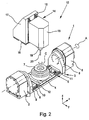
- Fig. 2 shows an embodiment of the machine tool 13 according to the invention in a perspective side view.
- the machine tool 13 comprises a workpiece carrier 1 according to the invention Fig. 1 and a tool holder 14.
- the tool holder 14 consists of a stator 17 and a headstock 18, wherein on the headstock 18 in the lower region a vertically arranged spindle 19 is provided for receiving a tool 20, in this case an end mill, for processing a - not shown - workpiece is used.
- the machine tool 13 is a numerical control for controlling and regulating the individual drives of the linear axes x, y, z and the axes of rotation A. , C and a measuring system consisting of several Measuring units, wherein the measuring system can detect the position and position of the workpiece holder 4 and the tool holder 14.
- the part of the tool holder 14, which receives the tool 20, d. H. the headstock 18, can be moved by means of a first adjusting means 15 along a first adjusting axis z.
- a first adjusting means 15 along a first adjusting axis z.
- the vertical distance of the tool 20 to the rotation axis A is adjustable.
- the first adjusting axis z extends vertically and orthogonal to the rotation axis A.
- the tool holder 14 is additionally equipped with a second adjusting means 16 that a method of tool holder 14 - and thus also the headstock 18th or the tool 20 - along a second adjusting axis y allows.
- the second adjusting axis y extends horizontally and is both orthogonal to the axis of rotation A and orthogonal to the first adjusting axis z.
- the second adjusting axis y allows positioning of the tool 20 with respect to the horizontal distance of the tool 20 to the rotation axis A.
- both the first adjusting means 15 and the second adjusting means 16 are fixed to the stator 17, so that in the present case the headstock 18 is secured via the first adjusting means 15 on the stator 17, whereby the headstock 18 relative to the stator 17 - along the first Adjusting axis z - can be moved.
- the workpiece which can be machined with the tool 20 which is rotatably arranged in the spindle 19, is fastened to the cradle 3 during machining on the faceplate 7 of the subassembly 4.
- the workpiece can be positioned relative to the tool 20 by rotation about the partial rotation axis C and / or about the rotation axis A as well as by a linear displacement along the linear axis x.
- Fig. 3 shows a second embodiment of a workpiece carrier 1, wherein the workpiece carrier 1 shown here only by the in Fig. 1 shows that a workpiece carrier 4, a carriage 4 'instead of a sub-unit 4 is provided.
- the carriage 4 ' can be positioned by means of the moving unit 5 on the rotatable cradle 3 and also serves to receive a workpiece to be machined or a workpiece holder.
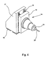
- Fig. 4 shows an alternative embodiment of a tool holder 14 for a machine tool 13, both with a workpiece carrier 1 according to Fig. 1 as with a workpiece carrier 1 according to Fig. 2 can be used.
- the tool holder 14 in turn comprises a stand 17 and a headstock 18.
- the difference of this tool holder 14 to the in Fig. 2 shown tool holder 14 is that the spindle 19 in the in Fig. 4 illustrated embodiment is mounted horizontally on the headstock 18.
- the horizontal arrangement of the spindle 19 on the headstock 18 results in a plurality of complementary processing options and positions compared to - in Fig. 2 shown - vertical arrangement of the spindle 19.
- the in Fig. 4 shows an alternative embodiment of a tool holder 14 for a machine tool 13, both with a workpiece carrier 1 according to Fig. 1 as with a workpiece carrier 1 according to Fig. 2 can be used.
- the tool holder 14 in turn comprises a stand 17 and a headstock 18.
- FIG. 4 shown tool holder 14 and the stator 17 has a first adjusting means 15 and a second adjusting means 16, wherein the headstock 18 is in turn secured by means of the first adjusting means 15 on the stator 17.
- the headstock 18 can thereby be moved relative to the stator 17.
Landscapes
- Engineering & Computer Science (AREA)
- Mechanical Engineering (AREA)
- Machine Tool Units (AREA)
Claims (12)
- Support de pièce, en particulier table pivotante rotative, comprenant au moins un plateaux verticaux (2), au moins un berceau (3) et un contre-palier (6), le berceau (3) étant monté sur le plateaux verticaux (2) et sur le contre-palier (6) de manière à pouvoir tourner autour d'un axe de rotation (A) s'étendant entre le plateaux verticaux (2) et le contre-palier (6) et au moins un porte-pièce (4) étant prévu sur le berceau (3), et
le plateaux verticaux (2) présentant un entraînement électrique, avec lequel le berceau (3) peut être tourné"
caractérisé en ce que
l'au moins un porte-pièce (4) peut être déplacé avec une unité de déplacement (5) le long d'un axe linéaire (x), l'axe linéaire (x) s'étendant parallèlement à l'axe de rotation (A),
un système de mesure détectant la position ou l'emplacement du porte-pièce (4) et une commande numérique sont prévus, et le système de mesure est connecté électriquement à l'entraînement électrique de le plateaux verticaux (2) et à l'unité de déplacement (5) du porte-pièce (4), de telle sorte que la position ou l'emplacement du porte-pièce (4) puissent être commandés et réglés au moyen de la commande numérique. - Support de pièce selon la revendication 1, caractérisé en ce que le contre-palier (6) dispose également d'un entraînement électrique, qui est commandé de manière synchronisée avec l'entraînement de le plateaux verticaux (2).
- Support de pièce selon la revendication 1 ou 2, caractérisé en ce que l'au moins un porte-pièce (4) est un plateaux diviseur, qui dispose d'un plateau (7) pour le montage d'au moins une pièce, le plateau (7) pouvant tourner autour d'un pièce axe de rotation (C) s'étendant perpendiculairement à l'axe linéaire (x).
- Support de pièce selon l'une quelconque des revendications 1 à 3, caractérisé en ce que le berceau (3) dispose d'une plaque de base (8), sur laquelle l'unité de déplacement (5) est prévue, la plaque de base (8) étant disposée de préférence de manière décalée par rapport à l'axe de rotation (A).
- Support de pièce selon l'une quelconque des revendications 1 à 4, caractérisé en ce que l'unité de déplacement (5) comprend au moins deux rails parallèles (10) et au moins une broche d'entraînement (11) pouvant être commandée et réglée.
- Support de pièce selon l'une quelconque des revendications 3 à 5, caractérisé en ce que le système de mesure est connecté électriquement à l'entraînement du plateau (7).
- Machine-outil comprenant un support de pièce (1) selon l'une quelconque des revendications 1 à 6 et un porte-outil (14), caractérisée en ce que le porte-outil (14) ou la partie du porte-outil (14) qui reçoit l'outil peut être déplacé(e) à l'aide d'un premier moyen de commande (15) le long d'un premier axe de commande (z), et
la commande et le système de mesure détectant la position ou l'emplacement du porte-pièce (4) sont prévus de telle sorte qu'ils soient connectés aux entraînements électriques individuels des axes linéaires (x, y, z) et des axes de rotation (A, C), de telle sorte que la position ou l'emplacement du porte-pièce (4) puissent être commandés et réglés au moyen de la commande. - Machine-outil selon la revendication 7, caractérisée en ce que le porte-outil (14) ou la partie du porte-outil (14) qui reçoit l'outil peuvent être déplacés à l'aide d'un deuxième moyen de commande (16) le long d'un deuxième axe de commande (y), le deuxième axe de commande (y) s'étendant perpendiculairement à l'axe linéaire (x) du support de pièce (1) et perpendiculairement au premier axe de commande (z).
- Machine-outil selon la revendication 7 ou 8, caractérisée en ce que le support de pièce (1) peut être déplacé avec un troisième moyen de commande le long du deuxième axe de commande (y), le troisième moyen de commande étant positionné sous le plateaux verticaux (2) et sous le contre-palier (6) de telle sorte que le plateaux verticaux (2), le berceau (3) et le contre-palier (6) puissent être déplacés linéairement le long du deuxième axe de commande (y), le deuxième axe de commande (y) s'étendant perpendiculairement à l'axe linéaire (x) du support de pièce (1) et perpendiculairement au premier axe de commande (z).
- Machine-outil selon l'une quelconque des revendications 7 à 9, caractérisée en ce que le porte-outil (14) présente un support (17) et une boîte de broche (18), la boîte de broche (18) étant fixée sur le support (17) au moyen du premier moyen de commande (15), de telle sorte que la boîte de broche (18) puisse être déplacée par rapport au support (17) et le porte-outil (14) présentant de préférence une broche (19) qui peut tourner au moins dans son plan de fixation.
- Machine-outil selon l'une quelconque des revendications 7 à 10, caractérisée en ce que le support de pièce (1) et le porte-outil (14) sont fixés sur au moins un bâti de machine commun.
- Machine-outil selon l'une quelconque des revendications 7 à 11, caractérisée en ce que les axes linéaires individuels (x, y, z) et les axes de rotation individuelle (A, C) sont chacun pourvus d'un entraînement propre et d'une unité de mesure propre, les entraînements étant commandés et régulés par le biais d'une commande numérique.
Applications Claiming Priority (1)
| Application Number | Priority Date | Filing Date | Title |
|---|---|---|---|
| DE102009042579A DE102009042579A1 (de) | 2009-09-24 | 2009-09-24 | Werkstückträger, insbesondere Drehschwenktisch |
Publications (2)
| Publication Number | Publication Date |
|---|---|
| EP2301712A1 EP2301712A1 (fr) | 2011-03-30 |
| EP2301712B1 true EP2301712B1 (fr) | 2013-07-03 |
Family
ID=43221936
Family Applications (1)
| Application Number | Title | Priority Date | Filing Date |
|---|---|---|---|
| EP10010518.8A Active EP2301712B1 (fr) | 2009-09-24 | 2010-09-24 | Support de pièce à usiner et machine-outil |
Country Status (2)
| Country | Link |
|---|---|
| EP (1) | EP2301712B1 (fr) |
| DE (1) | DE102009042579A1 (fr) |
Cited By (1)
| Publication number | Priority date | Publication date | Assignee | Title |
|---|---|---|---|---|
| EP4046744A1 (fr) | 2021-02-23 | 2022-08-24 | Klaus-Dieter Klement Verwaltungs GmbH | Dispositif porteur, ainsi que procédé de fonctionnement d'un dispositif porteur |
Families Citing this family (17)
| Publication number | Priority date | Publication date | Assignee | Title |
|---|---|---|---|---|
| JP5291820B2 (ja) * | 2011-05-26 | 2013-09-18 | ファナック株式会社 | 揺動体の揺動制御装置及び工作機械 |
| DE102016226319B4 (de) | 2015-12-31 | 2022-03-17 | Hyundai Wia Corporation | Kipptisch für ein Bearbeitungszentrum |
| CN107717543B (zh) * | 2017-10-25 | 2023-11-17 | 广东宏石激光技术股份有限公司 | 一种工装夹具 |
| CN107758238A (zh) * | 2017-10-27 | 2018-03-06 | 苏州听毅华环保科技有限公司 | 一种工件旋转机构 |
| CN110253317A (zh) * | 2019-06-11 | 2019-09-20 | 东莞盛翔精密金属有限公司 | 通用四轴定位治具 |
| CN111037318B (zh) * | 2019-12-31 | 2025-03-21 | 科德数控股份有限公司 | 多轴转台 |
| CN110977416A (zh) * | 2020-01-07 | 2020-04-10 | 巴士麦普科技(武汉)有限公司 | 用于组装汽车遮阳板上卡簧的压合工装 |
| CN112743268A (zh) * | 2020-12-30 | 2021-05-04 | 合肥亚美科技有限责任公司 | 底盘变位器 |
| CN112881041B (zh) * | 2021-01-11 | 2022-10-25 | 中车青岛四方机车车辆股份有限公司 | 轴箱定位装置及构架试验装置 |
| CN113084669A (zh) * | 2021-03-08 | 2021-07-09 | 东莞长盈精密技术有限公司 | 打磨治具、打磨设备、及打磨方法 |
| CN113118791B (zh) * | 2021-05-20 | 2024-08-23 | 浙江冠欣虹智能科技有限公司 | 一种五轴旋转工作台 |
| CN113798900B (zh) * | 2021-09-08 | 2024-01-12 | 合肥众石机电科技有限公司 | 一种工件角向调整装置和角向工件运送系统 |
| CN113649724A (zh) * | 2021-09-13 | 2021-11-16 | 江苏申阳电梯部件有限公司 | 一种主轴组件的自动焊接装置 |
| CN114535669A (zh) * | 2021-12-23 | 2022-05-27 | 成都市鸿侠科技有限责任公司 | 一种外侧梁加工工艺及工装 |
| EP4486533A1 (fr) * | 2022-03-01 | 2025-01-08 | ODeCon engineering GmbH | Machine-outil à commande numérique, entraînement et procédé d'usinage d'une pièce |
| DE102022104800A1 (de) | 2022-03-01 | 2023-09-07 | ODeCon Engineering GmbH | Verfahren zur additiven Fertigung mittels Laserschweißen sowie hierfür ausgebildete CNC-Maschine |
| CN122033660A (zh) * | 2026-04-16 | 2026-05-15 | 苏州义联工业科技有限公司 | 一种阀体定位加工工装 |
Citations (1)
| Publication number | Priority date | Publication date | Assignee | Title |
|---|---|---|---|---|
| FR2402385A7 (en) * | 1977-09-02 | 1979-03-30 | Gnecchi Luig Off Mec | Machine cutting polishing and shaping marble - has inclinable slide-mounted turntable beneath primary and secondary machining arms |
Family Cites Families (4)
| Publication number | Priority date | Publication date | Assignee | Title |
|---|---|---|---|---|
| DE1122807B (de) * | 1958-03-08 | 1962-01-25 | Jose Picanol | Maschine zum Fraesen von Verzahnungen von Kegel- und Hyperboloidzahnraedern |
| US3700228A (en) * | 1970-09-25 | 1972-10-24 | Robert E Peale | Adjustable axis work support |
| FR2290981A1 (fr) * | 1974-07-01 | 1976-06-11 | Romeu Ramon | Fraiseuse universelle |
| DE10259215A1 (de) * | 2002-12-17 | 2004-07-15 | Mfs Maschinenfabrik Gmbh | Werkzeugmaschine mit Direktantrieb |
-
2009
- 2009-09-24 DE DE102009042579A patent/DE102009042579A1/de not_active Withdrawn
-
2010
- 2010-09-24 EP EP10010518.8A patent/EP2301712B1/fr active Active
Patent Citations (1)
| Publication number | Priority date | Publication date | Assignee | Title |
|---|---|---|---|---|
| FR2402385A7 (en) * | 1977-09-02 | 1979-03-30 | Gnecchi Luig Off Mec | Machine cutting polishing and shaping marble - has inclinable slide-mounted turntable beneath primary and secondary machining arms |
Cited By (2)
| Publication number | Priority date | Publication date | Assignee | Title |
|---|---|---|---|---|
| EP4046744A1 (fr) | 2021-02-23 | 2022-08-24 | Klaus-Dieter Klement Verwaltungs GmbH | Dispositif porteur, ainsi que procédé de fonctionnement d'un dispositif porteur |
| DE102021104311A1 (de) | 2021-02-23 | 2022-08-25 | Klaus-Dieter Klement Verwaltungs Gmbh | Trägervorrichtung sowie Verfahren zum Betrieb einer Trägervorrichtung |
Also Published As
| Publication number | Publication date |
|---|---|
| DE102009042579A1 (de) | 2011-03-31 |
| EP2301712A1 (fr) | 2011-03-30 |
Similar Documents
| Publication | Publication Date | Title |
|---|---|---|
| EP2301712A1 (fr) | Machine-outil et support de pièce à usiner | |
| EP0737544B1 (fr) | Machine-outil avec plusieurs broches | |
| EP1188511B1 (fr) | Machine-outil avec un chariot porte-outil motorisé | |
| DE102004010984B3 (de) | Werkzeugmaschine zur spanenden Bearbeitung eines Werkstücks | |
| DE60303672T2 (de) | Werkzeugmaschine | |
| EP3027355A2 (fr) | Machine d'usinage | |
| EP2714310A1 (fr) | Porte-outils et machine-outil pourvue dudit porte-outils | |
| EP2344301B1 (fr) | Machine-outil | |
| EP2762254A1 (fr) | Tour à vilebrequins et fraiseuse ainsi que tourelle revolver à cet effet | |
| WO2002081132A2 (fr) | Machine-outil | |
| EP3999273B1 (fr) | Machine-outil et procédé de laminage de pièces rotatives ayant des profilés en forme de rainure | |
| EP1189726B1 (fr) | Machine-outil | |
| EP1832383B1 (fr) | Machine-outil | |
| EP3887091B1 (fr) | Machine-outil avec un premier et un deuxieme support de pieces | |
| DE20118456U1 (de) | Werkzeugmaschine | |
| EP1025953A1 (fr) | Machine-outil | |
| EP1466684B1 (fr) | Machine-outil pour l'usinage des pièces, en particulier des vilebrequins et des arbres à cames, avec au moins un outil pour le fraisage intérieur | |
| EP3334559B1 (fr) | Machine-outil | |
| EP0453875B2 (fr) | Machine pour le travail du métal par enlèvement de copeaux | |
| WO2007016910A2 (fr) | Procede et dispositif pour usiner des surfaces de pieces | |
| DE102018120936A1 (de) | Werkzeugmaschine | |
| EP3807044B1 (fr) | Dispositif d'usinage pour usiner des pièces et procédé d'usinage | |
| DE3843795C2 (fr) | ||
| DE3936699C2 (de) | Aufsatzgerät für eine Werkzeug-Schleifmaschine | |
| DE2505397A1 (de) | Vorrichtung zum spanabhebenden bearbeiten von zahnraedern |
Legal Events
| Date | Code | Title | Description |
|---|---|---|---|
| PUAI | Public reference made under article 153(3) epc to a published international application that has entered the european phase |
Free format text: ORIGINAL CODE: 0009012 |
|
| AK | Designated contracting states |
Kind code of ref document: A1 Designated state(s): AL AT BE BG CH CY CZ DE DK EE ES FI FR GB GR HR HU IE IS IT LI LT LU LV MC MK MT NL NO PL PT RO SE SI SK SM TR |
|
| AX | Request for extension of the european patent |
Extension state: BA ME RS |
|
| 17P | Request for examination filed |
Effective date: 20110930 |
|
| 17Q | First examination report despatched |
Effective date: 20111220 |
|
| GRAP | Despatch of communication of intention to grant a patent |
Free format text: ORIGINAL CODE: EPIDOSNIGR1 |
|
| GRAS | Grant fee paid |
Free format text: ORIGINAL CODE: EPIDOSNIGR3 |
|
| GRAA | (expected) grant |
Free format text: ORIGINAL CODE: 0009210 |
|
| AK | Designated contracting states |
Kind code of ref document: B1 Designated state(s): AL AT BE BG CH CY CZ DE DK EE ES FI FR GB GR HR HU IE IS IT LI LT LU LV MC MK MT NL NO PL PT RO SE SI SK SM TR |
|
| REG | Reference to a national code |
Ref country code: GB Ref legal event code: FG4D Free format text: NOT ENGLISH |
|
| REG | Reference to a national code |
Ref country code: CH Ref legal event code: EP Ref country code: AT Ref legal event code: REF Ref document number: 619423 Country of ref document: AT Kind code of ref document: T Effective date: 20130715 |
|
| REG | Reference to a national code |
Ref country code: IE Ref legal event code: FG4D Free format text: LANGUAGE OF EP DOCUMENT: GERMAN |
|
| REG | Reference to a national code |
Ref country code: DE Ref legal event code: R096 Ref document number: 502010003833 Country of ref document: DE Effective date: 20130822 |
|
| PG25 | Lapsed in a contracting state [announced via postgrant information from national office to epo] |
Ref country code: SI Free format text: LAPSE BECAUSE OF FAILURE TO SUBMIT A TRANSLATION OF THE DESCRIPTION OR TO PAY THE FEE WITHIN THE PRESCRIBED TIME-LIMIT Effective date: 20130703 |
|
| REG | Reference to a national code |
Ref country code: NL Ref legal event code: VDEP Effective date: 20130703 |
|
| REG | Reference to a national code |
Ref country code: LT Ref legal event code: MG4D |
|
| PG25 | Lapsed in a contracting state [announced via postgrant information from national office to epo] |
Ref country code: NO Free format text: LAPSE BECAUSE OF FAILURE TO SUBMIT A TRANSLATION OF THE DESCRIPTION OR TO PAY THE FEE WITHIN THE PRESCRIBED TIME-LIMIT Effective date: 20131003 Ref country code: LT Free format text: LAPSE BECAUSE OF FAILURE TO SUBMIT A TRANSLATION OF THE DESCRIPTION OR TO PAY THE FEE WITHIN THE PRESCRIBED TIME-LIMIT Effective date: 20130703 Ref country code: CY Free format text: LAPSE BECAUSE OF FAILURE TO SUBMIT A TRANSLATION OF THE DESCRIPTION OR TO PAY THE FEE WITHIN THE PRESCRIBED TIME-LIMIT Effective date: 20130710 Ref country code: PT Free format text: LAPSE BECAUSE OF FAILURE TO SUBMIT A TRANSLATION OF THE DESCRIPTION OR TO PAY THE FEE WITHIN THE PRESCRIBED TIME-LIMIT Effective date: 20131104 Ref country code: SE Free format text: LAPSE BECAUSE OF FAILURE TO SUBMIT A TRANSLATION OF THE DESCRIPTION OR TO PAY THE FEE WITHIN THE PRESCRIBED TIME-LIMIT Effective date: 20130703 Ref country code: HR Free format text: LAPSE BECAUSE OF FAILURE TO SUBMIT A TRANSLATION OF THE DESCRIPTION OR TO PAY THE FEE WITHIN THE PRESCRIBED TIME-LIMIT Effective date: 20130703 Ref country code: IS Free format text: LAPSE BECAUSE OF FAILURE TO SUBMIT A TRANSLATION OF THE DESCRIPTION OR TO PAY THE FEE WITHIN THE PRESCRIBED TIME-LIMIT Effective date: 20131103 |
|
| PG25 | Lapsed in a contracting state [announced via postgrant information from national office to epo] |
Ref country code: NL Free format text: LAPSE BECAUSE OF FAILURE TO SUBMIT A TRANSLATION OF THE DESCRIPTION OR TO PAY THE FEE WITHIN THE PRESCRIBED TIME-LIMIT Effective date: 20130703 Ref country code: FI Free format text: LAPSE BECAUSE OF FAILURE TO SUBMIT A TRANSLATION OF THE DESCRIPTION OR TO PAY THE FEE WITHIN THE PRESCRIBED TIME-LIMIT Effective date: 20130703 Ref country code: PL Free format text: LAPSE BECAUSE OF FAILURE TO SUBMIT A TRANSLATION OF THE DESCRIPTION OR TO PAY THE FEE WITHIN THE PRESCRIBED TIME-LIMIT Effective date: 20130703 Ref country code: ES Free format text: LAPSE BECAUSE OF FAILURE TO SUBMIT A TRANSLATION OF THE DESCRIPTION OR TO PAY THE FEE WITHIN THE PRESCRIBED TIME-LIMIT Effective date: 20131014 Ref country code: LV Free format text: LAPSE BECAUSE OF FAILURE TO SUBMIT A TRANSLATION OF THE DESCRIPTION OR TO PAY THE FEE WITHIN THE PRESCRIBED TIME-LIMIT Effective date: 20130703 Ref country code: GR Free format text: LAPSE BECAUSE OF FAILURE TO SUBMIT A TRANSLATION OF THE DESCRIPTION OR TO PAY THE FEE WITHIN THE PRESCRIBED TIME-LIMIT Effective date: 20131004 |
|
| BERE | Be: lapsed |
Owner name: PEISELER G.M.B.H. & CO.KG Effective date: 20130930 |
|
| PG25 | Lapsed in a contracting state [announced via postgrant information from national office to epo] |
Ref country code: CY Free format text: LAPSE BECAUSE OF FAILURE TO SUBMIT A TRANSLATION OF THE DESCRIPTION OR TO PAY THE FEE WITHIN THE PRESCRIBED TIME-LIMIT Effective date: 20130703 |
|
| PG25 | Lapsed in a contracting state [announced via postgrant information from national office to epo] |
Ref country code: RO Free format text: LAPSE BECAUSE OF FAILURE TO SUBMIT A TRANSLATION OF THE DESCRIPTION OR TO PAY THE FEE WITHIN THE PRESCRIBED TIME-LIMIT Effective date: 20130703 Ref country code: EE Free format text: LAPSE BECAUSE OF FAILURE TO SUBMIT A TRANSLATION OF THE DESCRIPTION OR TO PAY THE FEE WITHIN THE PRESCRIBED TIME-LIMIT Effective date: 20130703 Ref country code: MC Free format text: LAPSE BECAUSE OF FAILURE TO SUBMIT A TRANSLATION OF THE DESCRIPTION OR TO PAY THE FEE WITHIN THE PRESCRIBED TIME-LIMIT Effective date: 20130703 Ref country code: DK Free format text: LAPSE BECAUSE OF FAILURE TO SUBMIT A TRANSLATION OF THE DESCRIPTION OR TO PAY THE FEE WITHIN THE PRESCRIBED TIME-LIMIT Effective date: 20130703 Ref country code: CZ Free format text: LAPSE BECAUSE OF FAILURE TO SUBMIT A TRANSLATION OF THE DESCRIPTION OR TO PAY THE FEE WITHIN THE PRESCRIBED TIME-LIMIT Effective date: 20130703 Ref country code: SK Free format text: LAPSE BECAUSE OF FAILURE TO SUBMIT A TRANSLATION OF THE DESCRIPTION OR TO PAY THE FEE WITHIN THE PRESCRIBED TIME-LIMIT Effective date: 20130703 |
|
| PLBE | No opposition filed within time limit |
Free format text: ORIGINAL CODE: 0009261 |
|
| STAA | Information on the status of an ep patent application or granted ep patent |
Free format text: STATUS: NO OPPOSITION FILED WITHIN TIME LIMIT |
|
| PG25 | Lapsed in a contracting state [announced via postgrant information from national office to epo] |
Ref country code: IT Free format text: LAPSE BECAUSE OF FAILURE TO SUBMIT A TRANSLATION OF THE DESCRIPTION OR TO PAY THE FEE WITHIN THE PRESCRIBED TIME-LIMIT Effective date: 20130703 |
|
| 26N | No opposition filed |
Effective date: 20140404 |
|
| REG | Reference to a national code |
Ref country code: FR Ref legal event code: ST Effective date: 20140530 |
|
| REG | Reference to a national code |
Ref country code: IE Ref legal event code: MM4A |
|
| REG | Reference to a national code |
Ref country code: DE Ref legal event code: R097 Ref document number: 502010003833 Country of ref document: DE Effective date: 20140404 |
|
| PG25 | Lapsed in a contracting state [announced via postgrant information from national office to epo] |
Ref country code: BE Free format text: LAPSE BECAUSE OF NON-PAYMENT OF DUE FEES Effective date: 20130930 Ref country code: IE Free format text: LAPSE BECAUSE OF NON-PAYMENT OF DUE FEES Effective date: 20130924 |
|
| PG25 | Lapsed in a contracting state [announced via postgrant information from national office to epo] |
Ref country code: FR Free format text: LAPSE BECAUSE OF NON-PAYMENT OF DUE FEES Effective date: 20130930 |
|
| GBPC | Gb: european patent ceased through non-payment of renewal fee |
Effective date: 20140924 |
|
| PG25 | Lapsed in a contracting state [announced via postgrant information from national office to epo] |
Ref country code: SM Free format text: LAPSE BECAUSE OF FAILURE TO SUBMIT A TRANSLATION OF THE DESCRIPTION OR TO PAY THE FEE WITHIN THE PRESCRIBED TIME-LIMIT Effective date: 20130703 |
|
| PG25 | Lapsed in a contracting state [announced via postgrant information from national office to epo] |
Ref country code: TR Free format text: LAPSE BECAUSE OF FAILURE TO SUBMIT A TRANSLATION OF THE DESCRIPTION OR TO PAY THE FEE WITHIN THE PRESCRIBED TIME-LIMIT Effective date: 20130703 Ref country code: MT Free format text: LAPSE BECAUSE OF FAILURE TO SUBMIT A TRANSLATION OF THE DESCRIPTION OR TO PAY THE FEE WITHIN THE PRESCRIBED TIME-LIMIT Effective date: 20130703 |
|
| PG25 | Lapsed in a contracting state [announced via postgrant information from national office to epo] |
Ref country code: BG Free format text: LAPSE BECAUSE OF FAILURE TO SUBMIT A TRANSLATION OF THE DESCRIPTION OR TO PAY THE FEE WITHIN THE PRESCRIBED TIME-LIMIT Effective date: 20130703 Ref country code: MK Free format text: LAPSE BECAUSE OF FAILURE TO SUBMIT A TRANSLATION OF THE DESCRIPTION OR TO PAY THE FEE WITHIN THE PRESCRIBED TIME-LIMIT Effective date: 20130703 Ref country code: HU Free format text: LAPSE BECAUSE OF FAILURE TO SUBMIT A TRANSLATION OF THE DESCRIPTION OR TO PAY THE FEE WITHIN THE PRESCRIBED TIME-LIMIT; INVALID AB INITIO Effective date: 20100924 Ref country code: GB Free format text: LAPSE BECAUSE OF NON-PAYMENT OF DUE FEES Effective date: 20140924 Ref country code: LU Free format text: LAPSE BECAUSE OF NON-PAYMENT OF DUE FEES Effective date: 20130924 |
|
| REG | Reference to a national code |
Ref country code: AT Ref legal event code: MM01 Ref document number: 619423 Country of ref document: AT Kind code of ref document: T Effective date: 20150924 |
|
| PG25 | Lapsed in a contracting state [announced via postgrant information from national office to epo] |
Ref country code: AT Free format text: LAPSE BECAUSE OF NON-PAYMENT OF DUE FEES Effective date: 20150924 |
|
| PG25 | Lapsed in a contracting state [announced via postgrant information from national office to epo] |
Ref country code: AL Free format text: LAPSE BECAUSE OF FAILURE TO SUBMIT A TRANSLATION OF THE DESCRIPTION OR TO PAY THE FEE WITHIN THE PRESCRIBED TIME-LIMIT Effective date: 20130703 |
|
| PGFP | Annual fee paid to national office [announced via postgrant information from national office to epo] |
Ref country code: DE Payment date: 20221121 Year of fee payment: 13 |
|
| PGFP | Annual fee paid to national office [announced via postgrant information from national office to epo] |
Ref country code: CH Payment date: 20220928 Year of fee payment: 13 |
|
| REG | Reference to a national code |
Ref country code: DE Ref legal event code: R119 Ref document number: 502010003833 Country of ref document: DE |
|
| REG | Reference to a national code |
Ref country code: CH Ref legal event code: PL |
|
| PG25 | Lapsed in a contracting state [announced via postgrant information from national office to epo] |
Ref country code: CH Free format text: LAPSE BECAUSE OF NON-PAYMENT OF DUE FEES Effective date: 20230930 |
|
| PG25 | Lapsed in a contracting state [announced via postgrant information from national office to epo] |
Ref country code: DE Free format text: LAPSE BECAUSE OF NON-PAYMENT OF DUE FEES Effective date: 20240403 Ref country code: CH Free format text: LAPSE BECAUSE OF NON-PAYMENT OF DUE FEES Effective date: 20230930 |