EP2301721A2 - Machine manuelle dotée d'un dispositif d'entraînement produit par vibration et procédé de fonctionnement de celui-ci - Google Patents
Machine manuelle dotée d'un dispositif d'entraînement produit par vibration et procédé de fonctionnement de celui-ci Download PDFInfo
- Publication number
- EP2301721A2 EP2301721A2 EP10170904A EP10170904A EP2301721A2 EP 2301721 A2 EP2301721 A2 EP 2301721A2 EP 10170904 A EP10170904 A EP 10170904A EP 10170904 A EP10170904 A EP 10170904A EP 2301721 A2 EP2301721 A2 EP 2301721A2
- Authority
- EP
- European Patent Office
- Prior art keywords
- energy
- hand
- drive device
- machine according
- operated machine
- Prior art date
- Legal status (The legal status is an assumption and is not a legal conclusion. Google has not performed a legal analysis and makes no representation as to the accuracy of the status listed.)
- Withdrawn
Links
- 238000000034 method Methods 0.000 title claims abstract description 6
- 238000004146 energy storage Methods 0.000 claims abstract description 16
- 230000033001 locomotion Effects 0.000 claims description 24
- 230000001105 regulatory effect Effects 0.000 claims description 4
- 230000008878 coupling Effects 0.000 claims description 3
- 238000010168 coupling process Methods 0.000 claims description 3
- 238000005859 coupling reaction Methods 0.000 claims description 3
- 238000012432 intermediate storage Methods 0.000 claims description 3
- 238000011084 recovery Methods 0.000 claims description 2
- 238000004064 recycling Methods 0.000 claims 1
- 230000007246 mechanism Effects 0.000 abstract description 2
- 238000005553 drilling Methods 0.000 abstract 1
- 238000009527 percussion Methods 0.000 description 4
- 230000001939 inductive effect Effects 0.000 description 3
- 230000008901 benefit Effects 0.000 description 2
- 239000003990 capacitor Substances 0.000 description 2
- 230000000694 effects Effects 0.000 description 2
- 230000009467 reduction Effects 0.000 description 2
- 238000003860 storage Methods 0.000 description 2
- 239000006096 absorbing agent Substances 0.000 description 1
- 238000010521 absorption reaction Methods 0.000 description 1
- 230000002411 adverse Effects 0.000 description 1
- 230000005540 biological transmission Effects 0.000 description 1
- 238000006243 chemical reaction Methods 0.000 description 1
- 230000006835 compression Effects 0.000 description 1
- 238000007906 compression Methods 0.000 description 1
- 239000007822 coupling agent Substances 0.000 description 1
- 238000013016 damping Methods 0.000 description 1
- 230000001419 dependent effect Effects 0.000 description 1
- 229920001971 elastomer Polymers 0.000 description 1
- 239000000806 elastomer Substances 0.000 description 1
- 239000012530 fluid Substances 0.000 description 1
- 230000006698 induction Effects 0.000 description 1
- 230000010354 integration Effects 0.000 description 1
- 230000004048 modification Effects 0.000 description 1
- 238000012986 modification Methods 0.000 description 1
- 230000010355 oscillation Effects 0.000 description 1
- 238000001845 vibrational spectrum Methods 0.000 description 1
Images


Classifications
-
- B—PERFORMING OPERATIONS; TRANSPORTING
- B25—HAND TOOLS; PORTABLE POWER-DRIVEN TOOLS; MANIPULATORS
- B25F—COMBINATION OR MULTI-PURPOSE TOOLS NOT OTHERWISE PROVIDED FOR; DETAILS OR COMPONENTS OF PORTABLE POWER-DRIVEN TOOLS NOT PARTICULARLY RELATED TO THE OPERATIONS PERFORMED AND NOT OTHERWISE PROVIDED FOR
- B25F5/00—Details or components of portable power-driven tools not particularly related to the operations performed and not otherwise provided for
- B25F5/006—Vibration damping means
-
- B—PERFORMING OPERATIONS; TRANSPORTING
- B25—HAND TOOLS; PORTABLE POWER-DRIVEN TOOLS; MANIPULATORS
- B25D—PERCUSSIVE TOOLS
- B25D11/00—Portable percussive tools with electromotor or other motor drive
-
- B—PERFORMING OPERATIONS; TRANSPORTING
- B25—HAND TOOLS; PORTABLE POWER-DRIVEN TOOLS; MANIPULATORS
- B25D—PERCUSSIVE TOOLS
- B25D17/00—Details of, or accessories for, portable power-driven percussive tools
- B25D17/24—Damping the reaction force
-
- B—PERFORMING OPERATIONS; TRANSPORTING
- B25—HAND TOOLS; PORTABLE POWER-DRIVEN TOOLS; MANIPULATORS
- B25D—PERCUSSIVE TOOLS
- B25D2250/00—General details of portable percussive tools; Components used in portable percussive tools
- B25D2250/141—Magnetic parts used in percussive tools
- B25D2250/145—Electro-magnetic parts
Definitions
- the invention relates to a hand-held machine with a vibration causing drive device and a method for operating a hand-held machine with a vibration causing drive device according to the preamble of the independent claims.
- Hand-held power tools especially hand-held power tools with a predominantly impact driven tool have inherently a low overall efficiency ⁇ .
- An overall efficiency ⁇ is understood to be the ratio of working or useful energy to the total energy supplied.
- these hand-held power tools due to their operation on strong to very strong vibration. It is known to act on the vibrations by means of coupled with the drive device so-called Gegenschwinger reducing by suitable counter-vibrations. However, drive energy is expended for the drive of the counteroscillator, which further reduces the overall efficiency ⁇ of the hand-held machine.
- passive vibration damping systems so-called absorbers, which are characterized by a pronounced resonance behavior and absorb mechanical vibration energy in the range of their resonance frequencies.
- the hand-held machine according to the invention with the features of the main claim has the advantage that a total efficiency ⁇ of the hand-held machine can be advantageously increased by a recuperation to recover energy from the vibrations and to provide at least a portion of the recovered energy.
- a hand-held machine is understood in particular to be a hand-held power tool, preferably a hand-held drill and / or chisel hammer.
- the recuperation device comprises a receiving element for receiving energy, in particular for absorbing kinetic energy, an energy converter for converting the energy into another, second form of energy, preferably electrical energy, and an energy store for intermediate storage of the second form of energy.
- a receiving element is understood in particular an element or an assembly which absorbs energy caused by vibrations that are caused inter alia in the drive device, preferably by this energy is set in motion.
- An energy converter is understood to mean a device which converts the energy received in the receiving element into another, second form of energy, preferably electrical energy.
- Such an energy converter can For example, based on electromagnetic principles, such as a magnetically excited magnetic coil, or based for example on a piezoelectric effect.
- the energy converter can also be constructed on a pneumatic effect, in particular as a compressor.
- a compressor By such a compressor, a kinetic energy is converted into a compression of a fluid.
- An energy store for temporary storage of the second form of energy can be embodied, for example, as an inductive, capacitive or electrochemical energy store, in particular a rechargeable battery or capacitor, or else, for example, be an accumulator.
- an arithmetic unit is furthermore provided, which determines at least one parameter of the vibration of the hand-guided machine from an output signal of the energy converter.
- the vibration condition of the hand-held machine can be monitored in a simple manner.
- a characteristic of the vibration is understood in particular to be an amplitude, a frequency, a time behavior or a vibration spectrum.
- the recuperation device has a switching element for a controllable release of at least part of the recovered energy. This advantageously ensures that the recovered energy can be used in a targeted manner.
- the at least one parameter of the vibration is used to control the delivery of at least a portion of the energy recovered, in particular to an actuation of the switching element of the recuperation device.
- recuperation device can be connected to the drive device, in particular to a power supply of the drive device, by at least one coupling means, via which at least a part of the recovered energy is supplied to the drive device.
- a coupling agent can, for example, as a Be executed line connection, in particular be designed as an electrical line connection.
- Does the hand-held machine according to the invention comprises a main energy storage to a power supply of the drive device, in particular a drive unit of the drive device, and is further provided a means by which at least a portion of the energy recovered via the Rekuperationsvorraum can be supplied to the main energy storage, so can in a particularly advantageous manner the overall efficiency of the hand-operated machine can be increased.
- the recuperation device is connected to a kinetic element which can be set in motion by at least part of the recovered energy.
- the movement of the kinetic element is controlled by the parameter of the vibration, in particular regulated by this.
- Another aspect of the invention relates to a method of operating a hand-held machine with a vibration causing drive device.
- the overall efficiency of the drive device is increased by a return of at least a part of the recuperation device recovery of energy from the vibrations in the drive device.
- FIG. 1 shows a schematic side view of a drill and / or chisel hammer 10 as an example of a hand-held machine, in particular a hand-held machine tool.
- the drill and / or chisel hammer 10 has a housing 12 and a handle device 14 arranged on the housing 12.
- the handle device 14 may be connected to the housing 12, in particular be elastically connected, or be designed in one piece with the housing 12.
- a tool holder 18 is further provided at one of the handle device 14 opposite end 16 of the housing 12.
- the tool holder 18 is in particular rotatably arranged on the housing 12.
- the tool holder 18 may in particular also be accommodated at least partially in the housing.
- the tool holder 18 further serves for receiving, in particular for exchangeable receiving a tool 20.
- the tool 20 has in the present example, a longitudinal extent 22.
- auxiliary handle device 24 serves to improve the handling of the hammer drill 10.
- the housing 12 of the hammer drill 10 further includes a drive device 26 which causes known dimensions in one operation vibrations, which can be transmitted via the housing 12 and the handle device 14 and the auxiliary handle device 24 to a user.
- the drive device 26 has a drive unit 28, a translation unit 30 and an output unit 32.
- the drive unit 28 is formed by a motor 34, in particular an electric motor 35.
- the translation unit 30 is provided to translate a movement, in particular a rotational movement of the output unit 32, 34, 35 into a movement necessary for the drive of the tool 20.
- the translation unit 30 comprises a rotary drive gear 36 and an axial drive gear 38.
- the output unit 32 of the hammer drill 10 comprises a rotary drive 40 for rotationally driving the tool holder 18, which is operatively connected to the rotary drive gear 36, and a striking mechanism 42 for transmission of impact pulses on the tool 20, which in turn is operatively connected to the Axialantriebsgetriebe 38.
- the tool 20 received in the tool holder 18 is driven to a working or useful movement along its working direction 44, whereby only a fraction of the energy E supplied to the drive unit 28, 34, 35 is converted into a useful energy E out of the working or utility movement is converted.
- a Rekuperationsvorraum 100 for recovering energy E rekup from the vibrations and to provide at least a portion of the recovered energy E rekup, out .
- This energy E rekup, out of the Drive device 26 fed back overall efficiency ⁇ of the hand-held machine can be increased advantageously.
- ⁇ e out + e rekup . out e in
- an actuator 102 is provided on the housing 12.
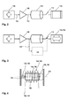
- FIG. 2 shows a schematic structure of a first embodiment of a Rekuperationsvorraum 100th
- the recuperation device 100 has at least one receiving element 104.
- the receiving element 104 is in particular designed such that it is able to absorb mechanical energy of the vibrations E mech vib at least in one oscillation plane.
- the receiving element 104 can receive mechanical energy E mech vib in two or more directions of movement.
- the receiving element 104 forwards the absorbed energy via an active connection 106 to an energy converter 108.
- the energy converter 108 is designed such that it converts the mechanical energy E mech vib received by the receiving element 104 into a second energy form, preferably electrical energy.
- the energy converter 108 in turn is connected via an operative connection 110 with an energy storage 112 in operative connection, wherein the energy storage 112 of the intermediate storage of the second form of energy is used.
- the energy store 112 in turn is connected at its output via a switching element 114 to a consumer 116. Via the switching element 114, a delivery of stored energy from the energy store 112 to the consumer 116 can be controlled or regulated.
- the consumer 116 may be, for example, the drive unit 28 of the hammer drill 10. It is also conceivable that the consumer 116 is a device in the hand-held machine tool, which performs additional functions.
- piezoelectric electromechanical, pneumatic and / or hydraulic drive principles are often used in hand-held machines - the drive device
- inductive, capacitive and / or piezoelectric pickup elements 104 in conjunction with a as Rectifier and / or integration arrangement executed energy converter 108 and a capacitive and / or inductive energy storage 112 into consideration.
- a mechanical receiving element 104 may be advantageously used with an executed as a compressor energy converter 108 with a print buffer as energy storage 112.
- FIG. 3 shows in solid line a first modification of the arrangement FIG. 2 ,
- the consumer 116 is designed as a kinetic element 118.
- the kinetic element 118 can be set in motion by supplying energy from the buffer 112.
- the kinetic element 118 can preferably be designed as a linear drive of a counter-oscillatory mass. If the counter-oscillator mass is set in motion by an energy supply from the energy store 112, a counterforce can be generated which acts to dampen the exciting vibrations.
- a computing unit 120 is further provided.
- the arithmetic unit 120 determines at least one parameter of the vibrations from an output signal 122 of the energy converter 108, which is substantially proportional to the energy input E mech vib .
- the arithmetic unit 120 is preferably connected to the switching element 114, so that an energy output E rekup, out from the energy store 112 can be controlled via the arithmetic unit 120.
- a movement of the kinetic element 118 can thus be controlled or regulated via the computing unit 120.
- the kinetic element 118 controls the movement of the kinetic element 118 such that the counterforce caused by the kinetic element 118 acts to damp the vibrations.
- FIG. 4 shows a simple embodiment of a combination of a receiving element 104 and a power converter 108.
- the receiving element 104 is formed as a mass-spring system 124.
- An axially along a line of movement 134 movably arranged mass body 126 of the mass-spring system 124 is formed in the present example as a permanent magnet 128, wherein the magnetic poles are arranged substantially perpendicular to the line of movement 134 in this example.
- the permanent magnet 128 is elastically supported on the front side in each case via an elastic member 130 relative to a housing 132, wherein the housing 132 preferably rests at least in the direction of the line of movement 134 substantially opposite the housing 12 of the hand-held machine.
- FIG. 4 shows two exemplary embodiments of an elastic member 130.
- the elastic member 130 is exemplified as a coil spring 136.
- the elastic element is alternatively or additionally designed as an elastic pad 138, in particular an elastic pad 138 formed from an elastomer.
- the elastic elements 130, 136, 138 form together with a mass of the mass body 126, the mass-spring system 124, which can be excited by the vibrations, which are caused inter alia by the drive device 26 to move. Since such mass-spring system 124 shows a pronounced resonance behavior, it may be provided in an advantageous development that at least one responsible for the resonance behavior characteristic of the mass-spring system 124 via an actuator 102 connected to the adjusting device made adjustable by the user is.
- the mass body 126, 128 is further arranged in an inner cylinder chamber 140, a coil 142.
- the coil 142 forms in the present example FIG. 4 the energy converter 108.
- the energy converter 108 further has a rectifier and integrator circuit, not shown here, which introduces electrical charges into the energy store 112 via an electrical connection 110.
- the energy store 112 is designed essentially as a capacitor.
- the arrangement shown can also be used as a kinetic element 118. If a voltage, in particular an alternating voltage, is applied to the coil 142, the mass body 126, 128 can be excited to deflect in the direction of the movement line 134.
- a voltage in particular an alternating voltage
- FIG. 5 shows a further embodiment of a hand-held machine 10a, for example, a hand-held power tool, preferably a drill, percussion drill, drill and / or chisel, in which the drive device 26a is received in a relative to the housing 12a elastically arranged inner housing 48.
- the inner housing 48 is resiliently supported by spring elements 50 relative to the housing 12a. The inner housing 48 can thus be moved in different directions of movement 52, 54 relative to the housing 12 a. In particular, vibrations generated by the driving device 26a are damped with respect to the housing 12a.
- two recuperation devices 100a are furthermore provided by way of example, which are arranged essentially along one of the directions of movement 52, 54 of the inner housing.
- the inner housing 48 may thus be formed as a component of the receiving element 104a.
- permanent magnets to be arranged on the inner housing 48, which induce a voltage in a coil provided as an energy converter 108a when the relative movement between the inner housing 48 and the housing 12a is caused by vibrations of the drive device 26a.
- piezoelectric elements or similar elements for energy absorption and energy conversion can also be used here.
- the hand-held machine 10a further has a main energy storage 56, preferably a battery unit 58 or battery unit, which is provided for a power supply of the drive unit 28a, which is preferably designed as a motor 34a, in particular electric motor 35a.
- the main energy storage 56, 58 is connected via an operative connection 60, preferably an electrical connection to the drive unit 28a, 34a, 35a.
- the energy storage device 112a of the recuperation device 100a is connected to the energy main storage 56 via a means formed from the switching element 114a and an active connection 62 in such a way that at least part of the energy E recuperated via the recuperation device can be supplied to the main energy storage 56.
- the means may be formed, for example, as an electrical switching element 114a and an electrical line 62 or in another example from a valve 114a and a pipeline 62.
- a coupling means is provided, via which the energy storage 112a can be coupled directly to the drive device 26a such that the recuperated from the energy storage 112a energy E , out directly the drive device 26a is supplied.
Landscapes
- Engineering & Computer Science (AREA)
- Mechanical Engineering (AREA)
- Percussive Tools And Related Accessories (AREA)
- General Electrical Machinery Utilizing Piezoelectricity, Electrostriction Or Magnetostriction (AREA)
Applications Claiming Priority (1)
| Application Number | Priority Date | Filing Date | Title |
|---|---|---|---|
| DE200910045002 DE102009045002A1 (de) | 2009-09-25 | 2009-09-25 | Handgeführte Maschine mit einer Vibration verursachten Antriebsvorrichtung und Verfahren zum Betrieb derselben |
Publications (2)
| Publication Number | Publication Date |
|---|---|
| EP2301721A2 true EP2301721A2 (fr) | 2011-03-30 |
| EP2301721A3 EP2301721A3 (fr) | 2014-12-17 |
Family
ID=43416489
Family Applications (1)
| Application Number | Title | Priority Date | Filing Date |
|---|---|---|---|
| EP10170904.6A Withdrawn EP2301721A3 (fr) | 2009-09-25 | 2010-07-27 | Machine manuelle dotée d'un dispositif d'entraînement produit par vibration et procédé de fonctionnement de celui-ci |
Country Status (2)
| Country | Link |
|---|---|
| EP (1) | EP2301721A3 (fr) |
| DE (1) | DE102009045002A1 (fr) |
Families Citing this family (3)
| Publication number | Priority date | Publication date | Assignee | Title |
|---|---|---|---|---|
| DE102013105829A1 (de) | 2013-06-06 | 2014-12-11 | Bilz Werkzeugfabrik Gmbh & Co. Kg | Werkzeugspannsystem |
| WO2014195054A1 (fr) | 2013-06-06 | 2014-12-11 | Bilz Werkzeugfabrik Gmbh & Co. Kg | Systeme de serrage d'outil |
| DE102014212391A1 (de) * | 2014-06-27 | 2015-12-31 | Robert Bosch Gmbh | Handwerkzeugmaschinenenergiewandler |
Family Cites Families (2)
| Publication number | Priority date | Publication date | Assignee | Title |
|---|---|---|---|---|
| DE102007060636A1 (de) * | 2007-12-17 | 2009-06-18 | Robert Bosch Gmbh | Elektrohandwerkzeug, insbesondere ein Bohr- und/oder Meißelhammer, mit einer Tilgereinheit |
| DE102008010100A1 (de) * | 2008-02-20 | 2009-08-27 | Robert Bosch Gmbh | Handwerkzeugmaschine |
-
2009
- 2009-09-25 DE DE200910045002 patent/DE102009045002A1/de not_active Withdrawn
-
2010
- 2010-07-27 EP EP10170904.6A patent/EP2301721A3/fr not_active Withdrawn
Non-Patent Citations (1)
| Title |
|---|
| None |
Also Published As
| Publication number | Publication date |
|---|---|
| DE102009045002A1 (de) | 2011-03-31 |
| EP2301721A3 (fr) | 2014-12-17 |
Similar Documents
| Publication | Publication Date | Title |
|---|---|---|
| DE69804112T2 (de) | Mit oszillierender masse arbeitendes werkzeug mit doppelsteifigkeitsfeder | |
| EP2265418B1 (fr) | Outil motorisé manuel | |
| EP1151827A1 (fr) | Outil à main à percussion électrique | |
| EP3056316B1 (fr) | Machine-outil portative | |
| EP2448715A1 (fr) | Machine-outil portative | |
| EP2457694A2 (fr) | Outil électrique | |
| EP2612732A1 (fr) | Dispositif d'outil manuel | |
| EP2512750A1 (fr) | Machine-outil à main comportant un dispositif d'amortissement des vibrations | |
| EP2314420B1 (fr) | Machine-outil électrique ayant un fonctionnement à marteau perforateur | |
| DE102009027422A1 (de) | Vorrichtung zur Reduktion und/oder Kompensation von Vibrationen, insbesondere für eine Handwerkzeugmaschine und zur Verwendung in Handwerkzeugmaschinen | |
| EP2089192A1 (fr) | Unité massique vibratoire pour des machines-outils à main pourvues d'un dispositif de percussion | |
| DE102007050307A1 (de) | Handwerkzeugmaschine | |
| EP2301721A2 (fr) | Machine manuelle dotée d'un dispositif d'entraînement produit par vibration et procédé de fonctionnement de celui-ci | |
| EP3822030A1 (fr) | Marteau perforateur et/ou burin avec agencement de mécanisme de percussion | |
| DE102007062248A1 (de) | Handwerkzeugmaschine mit einer, mindestens eine drehbar gelagerte Zwischenwelle umfassenden Getriebevorrichtung | |
| EP2331298B1 (fr) | Outil à accouplement de rattrapage | |
| WO2021094155A1 (fr) | Dispositif de type poignée pour une machine-outil | |
| DE202012012149U1 (de) | Handgehaltenes Arbeitsgerät mit drei schwingungsentkoppelten Baugruppen | |
| DE102016203931A1 (de) | Vorrichtung für eine Handwerkzeugmaschine | |
| EP2540452A1 (fr) | Mécanisme de percussion pneumatique avec volumes d'amortisseur pneumatique séparés | |
| DE10356928A1 (de) | Schlagwerk, Kolbenvorrichtung und Werkzeugmaschine | |
| EP2205408A1 (fr) | Système de poignée | |
| EP2448719A1 (fr) | Dispositif de réduction et/ou compensation de vibrations, en particulier pour une machine-outil à main, destiné à être utilisé dans des machines-outils à main | |
| DE102011077220A1 (de) | Elektrohandwerkzeug | |
| EP2512749B1 (fr) | Dispositif de machine-outil |
Legal Events
| Date | Code | Title | Description |
|---|---|---|---|
| PUAI | Public reference made under article 153(3) epc to a published international application that has entered the european phase |
Free format text: ORIGINAL CODE: 0009012 |
|
| AK | Designated contracting states |
Kind code of ref document: A2 Designated state(s): AL AT BE BG CH CY CZ DE DK EE ES FI FR GB GR HR HU IE IS IT LI LT LU LV MC MK MT NL NO PL PT RO SE SI SK SM TR |
|
| AX | Request for extension of the european patent |
Extension state: BA ME RS |
|
| PUAL | Search report despatched |
Free format text: ORIGINAL CODE: 0009013 |
|
| AK | Designated contracting states |
Kind code of ref document: A3 Designated state(s): AL AT BE BG CH CY CZ DE DK EE ES FI FR GB GR HR HU IE IS IT LI LT LU LV MC MK MT NL NO PL PT RO SE SI SK SM TR |
|
| AX | Request for extension of the european patent |
Extension state: BA ME RS |
|
| RIC1 | Information provided on ipc code assigned before grant |
Ipc: B25D 17/24 20060101ALI20141110BHEP Ipc: B25D 11/00 20060101ALI20141110BHEP Ipc: B25F 5/00 20060101AFI20141110BHEP |
|
| STAA | Information on the status of an ep patent application or granted ep patent |
Free format text: STATUS: THE APPLICATION IS DEEMED TO BE WITHDRAWN |
|
| 18D | Application deemed to be withdrawn |
Effective date: 20150203 |