EP2301820A1 - Montageverfahren eines Schienenfahrzeugs, und nach diesem Verfahren hergestelltes Schienenfahrzeug - Google Patents
Montageverfahren eines Schienenfahrzeugs, und nach diesem Verfahren hergestelltes Schienenfahrzeug Download PDFInfo
- Publication number
- EP2301820A1 EP2301820A1 EP10305974A EP10305974A EP2301820A1 EP 2301820 A1 EP2301820 A1 EP 2301820A1 EP 10305974 A EP10305974 A EP 10305974A EP 10305974 A EP10305974 A EP 10305974A EP 2301820 A1 EP2301820 A1 EP 2301820A1
- Authority
- EP
- European Patent Office
- Prior art keywords
- faces
- longitudinal
- equipment
- flag
- longitudinal faces
- Prior art date
- Legal status (The legal status is an assumption and is not a legal conclusion. Google has not performed a legal analysis and makes no representation as to the accuracy of the status listed.)
- Withdrawn
Links
Images

Classifications
-
- B—PERFORMING OPERATIONS; TRANSPORTING
- B61—RAILWAYS
- B61D—BODY DETAILS OR KINDS OF RAILWAY VEHICLES
- B61D17/00—Construction details of vehicle bodies
- B61D17/04—Construction details of vehicle bodies with bodies of metal; with composite, e.g. metal and wood body structures
- B61D17/043—Construction details of vehicle bodies with bodies of metal; with composite, e.g. metal and wood body structures connections between superstructure sub-units
- B61D17/045—The sub-units being construction modules
-
- B—PERFORMING OPERATIONS; TRANSPORTING
- B61—RAILWAYS
- B61D—BODY DETAILS OR KINDS OF RAILWAY VEHICLES
- B61D17/00—Construction details of vehicle bodies
- B61D17/04—Construction details of vehicle bodies with bodies of metal; with composite, e.g. metal and wood body structures
- B61D17/12—Roofs
Definitions
- the present invention relates to a method of mounting a rail vehicle car comprising a plurality of equipment of said vehicle, of the type comprising the steps of assembling two longitudinal faces with a frame and a roof.
- the invention also relates to a rail vehicle car obtained by such a mounting method.
- the crates of railway vehicles for example of the tramway box type, can be mounted in a modular manner by assembling the vehicle face elements to the frame and to a flag. Such an arrangement makes it possible to pre-equip the front elements with railway vehicle equipment such as the wiring of the door mechanisms, the electrical circuits and the seats fixed to the front elements.
- the complete prior equipment of the face elements is impossible, the assembly process is made more complex and a large number of assembly steps are necessary.
- the installation of the electrical circuits is also not optimized because a part of the circuits is on the front elements and another on the pavilions, and the connections can be made only once the flag mounted on the body, This prevents the equipment from being tested before the complete assembly of the railway vehicle. Another portion of the flag runs along the face and must be fixed on the transverse faces or end rings, and the connections can only be made once the flag mounted on the body.
- One of the aims of the invention is to overcome these disadvantages by proposing a mounting method in which the longitudinal faces can be completely pre-equipped and simplifying the mounting of the railway vehicle.
- the invention relates to a method of mounting a rail vehicle car of the type described above, wherein, prior to attachment to the frame, the longitudinal faces incorporate a structural portion of the flag arranged to allow the faces longitudinal to support the forces induced by the mounting of equipment arranged on the pavilion.
- the roof portion serving as a support reinforcement is integrated in the longitudinal face, it is possible to more fully integrate the internal equipment on the longitudinal face before assembly and facilitate the subsequent assembly of the rest of the flag.
- the invention also relates to a rail vehicle car of the type comprising two longitudinal faces with a frame and a roof, in which, prior to their attachment to the frame, the longitudinal faces incorporate a structural part of the roof arranged to allow the longitudinal faces to support the forces induced by the mounting of the equipment arranged on the pavilion.
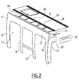
- a rail vehicle 1 comprises a frame 2, two longitudinal faces 4 fixed on either side of the frame 2 and a flag 6 fixed on the longitudinal faces 4, so as to form a substantially parallelepipedal vehicle 1.
- the described vehicle is for example a trolley case or a locomotive or any other railway vehicle carrying a large number of equipment arranged on the flag.
- each longitudinal face 4 comprises a plurality of vertical uprights 8 attached to a lower spar (not shown) and incorporating an upper spar 10, or "swing", and spaced from each other so as to define openings 12 between the uprights 8
- the openings may be closed by doors or by a lower panel and a window to define the windows of the vehicle.
- the longitudinal faces are equipped with a plurality of internal equipment of the railway vehicle, such as seats, door mechanisms, electrical circuits, trim panels, etc. (not shown)
- the pavilion 6 is also equipped with a plurality of internal equipment of the rail vehicle, such as the air conditioning system, the ceiling lights, the door actuating mechanisms, etc. (not shown)
- a plurality of equipment is also arranged on the pavilion 6, this equipment comprising the means for supplying electricity to the railway vehicle.
- the leaf members 10, structural portions 16 carrying the equipment and half-rings intercirculation 14 are assembled with the uprights 8 to form a longitudinal equipped face 4.
- the leaf elements 10, the structural parts 16 and the uprights 8 and the half-rings 14 form a single stamped welded assembly.
- the structural portion 16, which extends transversely and substantially perpendicular to the face 4, incorporates a longitudinal support 18 extending below it. This support 18 allows the housing of the door mechanisms, the attachment of equipment, and electrical circuits along the pavilion in the room.
- the wing elements 10, the structural parts 16 and the uprights 8 and the half-rings 14 are arranged to allow the longitudinal face 4 to withstand the forces induced by the mounting of the equipment arranged on the roof.
- the structural part 16 supports the elements for holding and fixing the equipment on the roof above the roof.
- the half-rings 14 form a support for a gusset of intercirculation extending between two successive cars and allow to pass the wiring between these cars.
- the half-rings 14 are each formed by a plate mounted vertically in the transverse direction
- Part of the equipment, such as electrical circuits and the like, intended to be arranged on the roof, may also be pre-fitted on the equipped face 4, for example in a wing 21 belonging to the wing 10 extending in the continuity of the face 4 above the portion 16.
- the leaf 10 has a structural holding function of the frame providing inertia to the assembly and further allows the routing of the cables inside this room.
- the faces 4 are further pre-equipped with hinge elements (not shown) to ensure the inter-cash articulation of the tram.
- An end beam 22 is further attached to each end portion of one of the equipped faces before mounting on the frame. These end crosspieces 22 extend in the transverse direction and connect the half-rings 14. According to one embodiment, the end cross member 22 is made in one piece with one of the half-rings.
- the two equipped longitudinal faces 4 are then mounted and fixed on the frame 2 so as to extend on either side thereof.
- the end cross members 22 are fixed to the other longitudinal face 4 so as to maintain the faces 4 between them.
- the frame can also be equipped with a plurality of equipment, such as acoustic insulation means, a floor covering, seats, etc., and painted before its assembly with the faces 4.
- equipment such as acoustic insulation means, a floor covering, seats, etc., and painted before its assembly with the faces 4.
- the structure of the roof 6 is greatly simplified and is formed of the parts 16 and a series of cross members 26 extending transversely between the parts 16 and evenly distributed between the sleepers 22.
- the cross members 26 are covered by a cover plate 28 to ensure the closure of the internal volume of the railway vehicle and the sealing of said vehicle.
- the sealing problems of the roof are solved, since the parts 16 are integrated and formed in one piece with the corresponding faces 4, only the seal between the parts 16 and the cover plate 28 must be ensured.
- the subassembly constituted by the crosspieces 26 and the cover plate 28 may incorporate interior layout elements such as ventilation ducts. It is in particular possible to fix an air-conditioning duct along the car, to the assembly 26, which further allows the ties 26 to be interconnected. The sheath is further attached to the sleepers 22.
- the crosspieces 26 are previously fixed or formed in one piece with the part 16 of one of the faces 4 before assembly of the crosspieces 26 with the other face 4.
- the method described above greatly simplifies the mounting of the rail vehicle and ensures a more complete pre-equipment of the faces 4. Thus, pre-assembled equipment can be tested before the final assembly of the vehicle.
Landscapes
- Engineering & Computer Science (AREA)
- Life Sciences & Earth Sciences (AREA)
- Wood Science & Technology (AREA)
- Mechanical Engineering (AREA)
- Automobile Manufacture Line, Endless Track Vehicle, Trailer (AREA)
- Body Structure For Vehicles (AREA)
Applications Claiming Priority (1)
| Application Number | Priority Date | Filing Date | Title |
|---|---|---|---|
| FR0956352A FR2950017B1 (fr) | 2009-09-16 | 2009-09-16 | Procede de montage d'un vehicule ferroviaire et vehicule ferroviaire obtenu par ledit procede |
Publications (1)
| Publication Number | Publication Date |
|---|---|
| EP2301820A1 true EP2301820A1 (de) | 2011-03-30 |
Family
ID=42124251
Family Applications (1)
| Application Number | Title | Priority Date | Filing Date |
|---|---|---|---|
| EP10305974A Withdrawn EP2301820A1 (de) | 2009-09-16 | 2010-09-10 | Montageverfahren eines Schienenfahrzeugs, und nach diesem Verfahren hergestelltes Schienenfahrzeug |
Country Status (4)
| Country | Link |
|---|---|
| EP (1) | EP2301820A1 (de) |
| CN (1) | CN102019936A (de) |
| BR (1) | BRPI1003509A8 (de) |
| FR (1) | FR2950017B1 (de) |
Cited By (1)
| Publication number | Priority date | Publication date | Assignee | Title |
|---|---|---|---|---|
| WO2017220745A1 (en) * | 2016-06-24 | 2017-12-28 | Bombardier Transportation Gmbh | Method of assembling a ceiling framework to a roof structure of a vehicle body of a rail vehicle |
Families Citing this family (4)
| Publication number | Priority date | Publication date | Assignee | Title |
|---|---|---|---|---|
| CN103921802B (zh) * | 2014-05-06 | 2016-04-20 | 唐山轨道客车有限责任公司 | 车顶装置及低地板有轨电车 |
| CN107878483B (zh) * | 2017-11-03 | 2019-06-21 | 中车青岛四方机车车辆股份有限公司 | 一种100%低地板有轨电车车体结构 |
| CN108909736B (zh) * | 2018-07-04 | 2019-08-16 | 通号轨道车辆有限公司 | 一种轨道车辆车顶结构 |
| IT201900023676A1 (it) * | 2019-12-11 | 2021-06-11 | Iveco Magirus | Telaio per un veicolo da soccorso e metodo per fabbricare tale telaio |
Citations (5)
| Publication number | Priority date | Publication date | Assignee | Title |
|---|---|---|---|---|
| EP0260200A1 (de) * | 1986-09-12 | 1988-03-16 | Gec Alsthom Sa | Kasten für Schienenpersonenwagen |
| EP0622285A1 (de) * | 1993-04-28 | 1994-11-02 | Gec Alsthom Transport Sa | Lichtbau-Wagenkasten eines Schienenfahrzeuges |
| FR2704507A1 (fr) * | 1993-04-28 | 1994-11-04 | Gec Alsthom Transport Sa | Caisse de véhicule ferroviaire formée par assemblage modulaire. |
| EP0990574A2 (de) * | 1998-09-30 | 2000-04-05 | DaimlerChrysler AG | Wagenkasten mit Dachabschlussplatte und Querspriegeln |
| EP0990572A2 (de) * | 1998-09-30 | 2000-04-05 | DaimlerChrysler AG | Wagenkasten mit Kastengerippe |
Family Cites Families (3)
| Publication number | Priority date | Publication date | Assignee | Title |
|---|---|---|---|---|
| CN100441935C (zh) * | 1996-03-19 | 2008-12-10 | 株式会社日立制作所 | 镶板结构体 |
| CN201193031Y (zh) * | 2008-08-14 | 2009-02-11 | 铁道部运输局 | 高强度大型铝合金车体 |
| CN201189864Y (zh) * | 2008-08-15 | 2009-02-04 | 铁道部运输局 | 铝合金车体 |
-
2009
- 2009-09-16 FR FR0956352A patent/FR2950017B1/fr active Active
-
2010
- 2010-09-10 EP EP10305974A patent/EP2301820A1/de not_active Withdrawn
- 2010-09-15 BR BRPI1003509A patent/BRPI1003509A8/pt not_active Application Discontinuation
- 2010-09-16 CN CN2010105199494A patent/CN102019936A/zh active Pending
Patent Citations (5)
| Publication number | Priority date | Publication date | Assignee | Title |
|---|---|---|---|---|
| EP0260200A1 (de) * | 1986-09-12 | 1988-03-16 | Gec Alsthom Sa | Kasten für Schienenpersonenwagen |
| EP0622285A1 (de) * | 1993-04-28 | 1994-11-02 | Gec Alsthom Transport Sa | Lichtbau-Wagenkasten eines Schienenfahrzeuges |
| FR2704507A1 (fr) * | 1993-04-28 | 1994-11-04 | Gec Alsthom Transport Sa | Caisse de véhicule ferroviaire formée par assemblage modulaire. |
| EP0990574A2 (de) * | 1998-09-30 | 2000-04-05 | DaimlerChrysler AG | Wagenkasten mit Dachabschlussplatte und Querspriegeln |
| EP0990572A2 (de) * | 1998-09-30 | 2000-04-05 | DaimlerChrysler AG | Wagenkasten mit Kastengerippe |
Cited By (1)
| Publication number | Priority date | Publication date | Assignee | Title |
|---|---|---|---|---|
| WO2017220745A1 (en) * | 2016-06-24 | 2017-12-28 | Bombardier Transportation Gmbh | Method of assembling a ceiling framework to a roof structure of a vehicle body of a rail vehicle |
Also Published As
| Publication number | Publication date |
|---|---|
| CN102019936A (zh) | 2011-04-20 |
| FR2950017A1 (fr) | 2011-03-18 |
| FR2950017B1 (fr) | 2017-07-07 |
| BRPI1003509A8 (pt) | 2017-09-12 |
| BRPI1003509A2 (pt) | 2013-01-08 |
Similar Documents
| Publication | Publication Date | Title |
|---|---|---|
| JP5526644B2 (ja) | 車両の車体構造 | |
| US6685254B2 (en) | Low floor mass transit vehicle | |
| EP2301820A1 (de) | Montageverfahren eines Schienenfahrzeugs, und nach diesem Verfahren hergestelltes Schienenfahrzeug | |
| EP0533582B1 (de) | Fahrerhaus für Schienenfahrzeuge | |
| EP1353837B1 (de) | Modul-kraftfahrzeug und assemblageverfahren | |
| KR20080044279A (ko) | 루프 모듈용 어댑터 서포트를 포함하는 차체, 이를 위한어댑터 서포트 및 상기 차체 제조 방법 | |
| KR20010066475A (ko) | 자동차의 후방필러 보강구조 | |
| EP1591357A1 (de) | Aufbau von Flugzeugrumpfpaneelen | |
| CN116811951B (zh) | 轨道车辆 | |
| KR101721091B1 (ko) | 철도 차량용 구조체 및 이를 구비한 철도 차량 | |
| EP3988447A1 (de) | Kompaktes hauptfahrwerksmodul für luftfahrzeug, das eine modulare montage ermöglicht | |
| JPH092323A (ja) | クロスメンバの構造 | |
| CN110382336A (zh) | 舱室模块以及配备有舱室模块的机动车 | |
| JP2019196104A (ja) | 車両の側部車体構造 | |
| JP4035810B2 (ja) | 車両のドア構造 | |
| JP4720327B2 (ja) | スライドドア車の下部車体構造 | |
| FR2613995A1 (fr) | Caisse autoportante de vehicule ferroviaire | |
| JP2010023632A (ja) | 車両の下部車体構造およびその組付け方法 | |
| JPH11268640A (ja) | 鉄道車両の製造方法と鉄道車両 | |
| JP2008037123A (ja) | 車体の上部構造 | |
| FR2704507A1 (fr) | Caisse de véhicule ferroviaire formée par assemblage modulaire. | |
| JP2016203716A (ja) | 後部ドア構造付き車両 | |
| JP2007131042A (ja) | キャブオーバ型車両の乗降口周縁部構造 | |
| JPS63270250A (ja) | 自動車のインストルメントパネル構造 | |
| US11708096B2 (en) | Side wall for a rail vehicle |
Legal Events
| Date | Code | Title | Description |
|---|---|---|---|
| PUAI | Public reference made under article 153(3) epc to a published international application that has entered the european phase |
Free format text: ORIGINAL CODE: 0009012 |
|
| AK | Designated contracting states |
Kind code of ref document: A1 Designated state(s): AL AT BE BG CH CY CZ DE DK EE ES FI FR GB GR HR HU IE IS IT LI LT LU LV MC MK MT NL NO PL PT RO SE SI SK SM TR |
|
| AX | Request for extension of the european patent |
Extension state: BA ME RS |
|
| STAA | Information on the status of an ep patent application or granted ep patent |
Free format text: STATUS: THE APPLICATION IS DEEMED TO BE WITHDRAWN |
|
| 18D | Application deemed to be withdrawn |
Effective date: 20111001 |