EP2301822A2 - Elektrisches Servolenksystem - Google Patents
Elektrisches Servolenksystem Download PDFInfo
- Publication number
- EP2301822A2 EP2301822A2 EP10178776A EP10178776A EP2301822A2 EP 2301822 A2 EP2301822 A2 EP 2301822A2 EP 10178776 A EP10178776 A EP 10178776A EP 10178776 A EP10178776 A EP 10178776A EP 2301822 A2 EP2301822 A2 EP 2301822A2
- Authority
- EP
- European Patent Office
- Prior art keywords
- relay contact
- power supply
- circuit
- capacitor
- relay
- Prior art date
- Legal status (The legal status is an assumption and is not a legal conclusion. Google has not performed a legal analysis and makes no representation as to the accuracy of the status listed.)
- Granted
Links
- 239000003990 capacitor Substances 0.000 claims abstract description 74
- 230000000087 stabilizing effect Effects 0.000 abstract description 4
- 238000000034 method Methods 0.000 description 11
- 230000007423 decrease Effects 0.000 description 9
- 230000008569 process Effects 0.000 description 7
- 230000007246 mechanism Effects 0.000 description 4
- 230000008859 change Effects 0.000 description 3
- 230000006866 deterioration Effects 0.000 description 2
- 238000010586 diagram Methods 0.000 description 2
- 230000009467 reduction Effects 0.000 description 2
- 239000000758 substrate Substances 0.000 description 2
- 230000002123 temporal effect Effects 0.000 description 2
- 230000004913 activation Effects 0.000 description 1
- 230000008878 coupling Effects 0.000 description 1
- 238000010168 coupling process Methods 0.000 description 1
- 238000005859 coupling reaction Methods 0.000 description 1
- 238000001514 detection method Methods 0.000 description 1
- 238000007599 discharging Methods 0.000 description 1
- 230000000694 effects Effects 0.000 description 1
- 230000005669 field effect Effects 0.000 description 1
- 230000004044 response Effects 0.000 description 1
Images


Classifications
-
- B—PERFORMING OPERATIONS; TRANSPORTING
- B62—LAND VEHICLES FOR TRAVELLING OTHERWISE THAN ON RAILS
- B62D—MOTOR VEHICLES; TRAILERS
- B62D5/00—Power-assisted or power-driven steering
- B62D5/04—Power-assisted or power-driven steering electrical, e.g. using an electric servo-motor connected to, or forming part of, the steering gear
- B62D5/0457—Power-assisted or power-driven steering electrical, e.g. using an electric servo-motor connected to, or forming part of, the steering gear characterised by control features of the drive means as such
- B62D5/0481—Power-assisted or power-driven steering electrical, e.g. using an electric servo-motor connected to, or forming part of, the steering gear characterised by control features of the drive means as such monitoring the steering system, e.g. failures
-
- G—PHYSICS
- G01—MEASURING; TESTING
- G01R—MEASURING ELECTRIC VARIABLES; MEASURING MAGNETIC VARIABLES
- G01R31/00—Arrangements for testing electric properties; Arrangements for locating electric faults; Arrangements for electrical testing characterised by what is being tested not provided for elsewhere
- G01R31/327—Testing of circuit interrupters, switches or circuit-breakers
- G01R31/3277—Testing of circuit interrupters, switches or circuit-breakers of low voltage devices, e.g. domestic or industrial devices, such as motor protections, relays, rotation switches
- G01R31/3278—Testing of circuit interrupters, switches or circuit-breakers of low voltage devices, e.g. domestic or industrial devices, such as motor protections, relays, rotation switches of relays, solenoids or reed switches
Definitions
- the invention relates to an electric power steering system.
- the electric power steering system includes a driving circuit that supplies a driving current to the motor on the basis of a power supply voltage, a control device that controls the operation of the driving circuit and a relay circuit that turns on or off a relay contact provided in a first power supply path that connects the driving circuit and a power supply to each other.
- a capacitor is provided between the relay contact and the driving circuit in order to stabilize the supply of power from the power source.
- an inrush current may flow from the power supply to the relay contact.
- the EPS includes a precharge circuit that is interposed in a second power supply path that bypasses the relay contact in order to prevent occurrence of the inrush current. Then, an ignition switch is turned on, the capacitor is charged (precharged) by the precharge circuit, and then the relay contact is turned on.
- an EPS that includes the precharge circuit provided with a switching element and a discharge circuit.
- the switching element is used for switching between the execution and termination of precharge.
- the discharge circuit has a circuit configuration similar to that of the precharge circuit, and is provided between the capacitor and the driving circuit.
- the relay circuit When the relay contact is normal and has no stuck-open fault, the relay circuit is activated and then the relay contact is actually turned on. Therefore, even when the capacitor is discharged in a state where precharge is stopped, the capacitor-side terminal voltage of the relay contact does not decrease but is kept at the power supply voltage. On the other hand, when the relay contact has a stuck-open fault, the relay contact is not actually turned on even when the relay circuit is activated. Therefore, when the capacitor is discharged in a state where precharge is stopped, the capacitor-side voltage of the relay contact decreases. Thus, when there is a voltage difference between both terminals of the relay contact after the capacitor is discharged in a state where precharge is stopped, it is determined that the relay contact has a stuck-open fault.
- the precharge circuit in order to detect the above-described stuck-open fault, the precharge circuit need to have a function of switching between the execution and termination of the precharge. Furthermore, it is necessary to provide a discharge circuit having a scale similar to that of the above-described precharge circuit between the capacitor and the driving circuit. As a result, the number of components of the control device increases.
- An aspect of the invention relates to an electric power steering system that includes: a motor that applies assist force for assisting steering operation to a steering system; a driving circuit that supplies a driving current to the motor on the basis of a power supply voltage, and that is formed by connecting switching arms, each of which is formed of a pair of switching elements connected in series, in parallel with each other; a controller that controls operation of the driving circuit; a relay circuit that turns on or off a relay contact provided in a first power supply path that connects the driving circuit and a power supply to each other; and a fault detector that detects a fault of the relay contact.
- a capacitor is interposed between the relay contact and the driving circuit.
- the relay circuit is activated after the capacitor is charged through a second power supply path that bypasses the relay contact when an ignition switch is turned on.
- the fault detector determines whether the relay contact has a stuck-open fault, in which the relay contact remains turned off, on the basis of a voltage difference between both terminals of the relay contact after the relay circuit is activated.
- a resistor is interposed in the second power supply path. The controller turns on both of the switching elements that constitute one of the switching arms when whether the relay contact has the stuck-open fault is determined.
- the capacitor-side terminal of the relay contact is connected to a power supply via only the second power supply path in which the resistor is provided.
- the terminal voltage decreases with a voltage drop caused by the resistor, and then a voltage difference occurs between both terminals of the relay contact.
- the capacitor-side terminal of the relay contact is connected to the power supply via the first power supply path in which no resistor is provided. Therefore, even when the capacitor is discharged via the switching arm in that state, a voltage difference does not occur between both terminals of the relay contact.
- the fault detector determines that the relay contact has a stuck-open fault if a voltage difference occurs between the both terminals of the relay contact when both switching elements that constitute one of the switching arms are turned on after the relay circuit is activated. Note that, when the capacitor is discharged via only one of the switching arms, no driving current is supplied to the motor when the capacitor is discharged. Therefore, no unintentional assist force is applied to the steering system.
- the precharge circuit is not required to have a function of switching between the execution and termination of the precharge, unlike the existing art.
- the capacitor is discharged by turning on both the pair of switching elements that constitute one of the switching arms of the driving circuit. Therefore, the discharge circuit is no longer required. Accordingly, it is possible to employ a circuit having a scale smaller than that of the precharge circuit. As a result, it is possible to reduce the number of components and reduce the area of the substrate. This makes it possible to reduce the cost and decrease the failure rate of the EPS.
- an electronic circuit that constitutes the fault detector may receive electric power supplied through a third power supply path electrically connected to the second power supply path when the ignition switch is turned on, and the fault detector may determine that the relay contact has a stuck-closed fault, in which the relay contact remains turned on, when electric power is supplied to the electronic circuit after the ignition switch is turned off and the relay circuit is deactivated.
- the first and second power supply paths each connect the power supply to the driving circuit and are electrically connected to each other, and the third power supply path is also electrically connected to the first power supply path via the second power supply path.
- the first and second power supply paths are interrupted. Therefore, no driving current is supplied from the power supply to the electronic circuit.
- the ignition switch is turned off, in a state where the relay contact is turned on, electric power is supplied from the power supply to the electronic circuit through the third power supply path electrically connected to the first power supply path via the second power supply path.
- the relay contact When the relay contact has no stuck-closed fault in which the relay contact remains turned on after the ignition switch is turned off and the relay circuit is deactivated in order to turn off the relay contact, no electric power is supplied to the electronic circuit. On the other hand, when the relay contact has a stuck-closed fault, electric power is supplied to the electronic circuit.
- the fault detector determines that the relay contact has a stuck-closed fault when electric power is supplied to the electronic circuit after the ignition switch is turned off and the relay circuit is deactivated.
- the controller may limit a duty ratio of a pulse signal that is input as a driving signal in the pair of switching elements that constitute one of the switching arms at or below a predetermined duty ratio in order to prevent a current flowing into the pair of switching elements from being excessive when the capacitor is discharged via the one of the switching arms to determine whether the relay contact has a stuck-open fault.
- an electric power steering system (EPS) 1 includes a steering shaft 3 to which a steering wheel 2 is fixed.
- the steering shaft 3 is coupled to a rack shaft 5 via a rack-and-pinion mechanism 4.
- the rotation of the steering shaft 3 resulting from steering operation is converted into linear reciprocating motion of the rack shaft 5 by the rack-and-pinion mechanism 4.
- the steering shaft 3 is formed by coupling a column shaft 8, an intermediate shaft 9 and a pinion shaft 10 to each other.
- the linear reciprocating motion of the rack shaft 5 resulting from the rotation of the steering shaft 3 is transmitted to knuckles (not shown) via tie rods 11 coupled to respective ends of the rack shaft 5. This changes the steered angles of steered wheels 12, that is, the traveling direction of a vehicle.
- the EPS 1 includes an EPS actuator 22 and an ECU 23.
- the EPS actuator 22 applies assist force for assisting steering operation to a steering system using a motor 21 as a driving source.
- the ECU 23 controls the operation of the EPS actuator 22.
- the EPS actuator 22 is a column assist-type EPS actuator.
- the motor 21 that serves as the driving source of the EPS actuator 22 is drivably coupled to the column shaft 8 via a reduction mechanism 25.
- a brush direct-current motor is employed as the motor 21.
- the motor 21 rotates with a driving current supplied from the ECU 23. The speed of rotation of the motor 21 is reduced by the reduction mechanism 25 and the rotation having the reduced speed is transmitted to the column shaft 8 to apply the motor torque to the steering system as assist force.
- a vehicle speed sensor 27 and a torque sensor 28 are connected to the ECU 23.
- the ECU 23 controls the operation of the EPS actuator 22, more specifically, the torque that is generated by the motor 21 that serves as a driving source, on the basis of a vehicle speed SPD and a steering torque ⁇ that are detected by these sensors to thereby execute control over assist force that is applied to the steering system.
- the ECU 23 includes a driving circuit 32 and a microcomputer 33.
- the driving circuit 32 supplies a driving current to the motor 21 on the basis of a voltage of a power supply 31.
- the microcomputer 33 serves as a controller and an electronic circuit that control the operation of the driving circuit 32 by outputting motor control signals Sm.
- the driving circuit 32 is formed by connecting a series circuit formed of a set of FETs (field-effect transistors) 35a and 35c and a series circuit formed of a set of FETs 35b and 35d in parallel with each other. A pair of switching elements connected in series is used as a base unit (switching arm).
- the driving circuit 32 is configured as a known H bridge circuit that is formed by connecting these two switching arms 36 and 37 in parallel with each other- Then, the motor 21 is connected to a connecting point 38a between the FETs 35a and 35c and a connecting point 38b between the FETs 35b and 35d.
- the motor control signals Sm output from the microcomputer 33 are used as gate on/off signals that determine the switching statuses of the FETs 35a to 35d that constitute the driving circuit 32. Then, each of the FETs 35a to 35d is turned on or off in response to the motor control signal Sm applied to its gate terminal, and the electric power of the power supply 31 is output to the motor 21.
- each motor control signal Sm is a pulse signal that has a duty ratio corresponding to a target assist force, and each of the FETs 35a to 35d is turned on in accordance with the duty ratio.
- the ECU 23 includes a relay circuit 42 that turns on or off a relay contact 41 interposed in a first power supply path L1 (path along the wide broken line a in FIG. 2 ) that connects the driving circuit 32 and the power supply 31 to each other.
- a capacitor 43 for stabilizing the supply of electric power is connected to the first power supply path L1 at a point between the relay contact 41 and the driving circuit 32.
- the high-potential terminal of the capacitor 43 is connected to the power supply 31 via a second power supply path L2 (path along the wide broken line b in FIG. 2 ) that bypasses the relay contact 41 and that connects the driving circuit 32 and the power supply 31 to each other. Note that the other end of the capacitor 43 is grounded.
- the relay circuit 42 includes the relay contact 41 and a relay coil 46 that generates electromagnetic force for turning on or off the relay contact 41.
- One end of the relay contact 41 is connected to the power supply 31, and the other end of the relay contact 41 is connected to the high-potential terminal of the capacitor 43 via a coil 47.
- the coil 47 functions as a filter for reducing a noise.
- a FET 48 is connected to one end of the relay coil 46, and the FET 48 is turned on or off on the basis of a relay control signal Sr output from the microcomputer 33.
- the relay circuit 42 is activated to turn on the relay contact on the basis of electromagnetic force generated by the relay coil 46 when the FET 48 is turned on or off.
- a resistor 51 is interposed in the second power supply path L2.
- An ignition switch 52 operated at the time of start-up of the vehicle is provided in the second power supply path L2.
- the capacitor 43 is charged (precharged) with current supplied through the second power supply path L2 in which the resistor 51 is provided in advance of activation of the relay circuit 42.
- the other end of the FET 48 connected to the relay coil 46 is connected to the second power supply path L2, and the second power supply path L2 and the first power supply path L1 are connected to each other via a diode (freewheeling diode) 53.
- a diode 53 is connected to the first power supply path L1 at a connecting point 55 at which the capacitor 43 is connected to the first power supply path L1.
- a diode 56 is provided in the second power supply path L2 in order to prevent backflow of current, which is returned via the diode 53, toward the power supply 31.
- a third power supply path L3 (path along the wide broken line c in FIG. 2 ) that branches from the second power supply path L2 is provided. Then, electric power is supplied through the third power supply path L3 to the microcomputer 33 and another electrical component 57 mounted in the vehicle. That is, the third power supply path L3 is connected to the first power supply path L1 via the resistor 51 of the second power supply path L2.
- the ECU 23 has a function of detecting a fault in the relay contact 41 on the basis of a voltage difference between both terminals of the relay contact 41.
- the microcomputer 33 activates the relay circuit 42 after completing precharge of the capacitor 43, causes the discharge of the capacitor 43, and then determines whether a fault, in which the relay contact 41 remains turned off (stuck-open fault), has occurred on the basis of a voltage difference between both terminals of the relay contact 41 at that time.
- the microcomputer 33 receives an IG signal Sig that indicates an on/off state of the ignition switch 52 from an upper level ECU (not shown). Then, the microcomputer 33 activates the relay circuit 42 after a lapse of a predetermined period of time required to complete precharge of the capacitor 43 after the ignition switch 52 is turned on. Thus, it is possible to prevent inrush current from flowing from the power supply 31 to the relay contact 41 when the relay contact 41 is turned on.
- a voltage sensor 61 is provided between the ignition switch 52 and the diode 56, and a voltage sensor 62 is provided between the capacitor 43-side terminal of the relay contact 41 and the coil 47.
- These voltage sensors 61 and 62 are connected to the microcomputer 33.
- the microcomputer 33 uses the voltage detected by the voltage sensor 61, that is, the power supply 31-side terminal voltage Va of the relay contact 41 after the ignition switch 52 is turned on, and the voltage detected by the voltage sensor 62, that is, the capacitor 43-side terminal voltage Vb of the relay contact 41, to detect a voltage difference ⁇ V between both terminals of the relay contact 41.
- the microcomputer 33 and the voltage sensors 61 and 62 constitute a fault detector.
- the microcomputer 33 turns on one of the switching arms 36 and 37, for example, the FETs 35a and 35c of the switching arm 36, after the relay circuit 42 is activated to thereby cause the discharge of the capacitor 43. Note that, because the capacitor 43 is discharged only via the switching arm 36, no driving current is supplied to the motor 21 while discharging, and no unintentional assist force is applied to the steering system. Specifically, the microcomputer 33 sets the duty ratio of each motor control signal Sm at or below a predetermined duty ratio (for example, 10%) at which a current flowing from the power supply 31 to the FETs 35a and 35c is prevented from being excessive.
- a predetermined duty ratio for example, 10%
- the relay contact 41 when the relay contact 41 is normal and has no stuck-open fault, if the ignition switch 52 is turned on (time t1), the power supply 31-side terminal voltage Va of the relay contact 41 immediately increases to the power supply voltage, and the capacitor 43-side terminal voltage Vb gradually increases. Then, when precharge of the capacitor 43 is completed and the relay circuit 42 is activated (time t2), the relay contact 41 is turned on, the capacitor 43-side terminal voltage Vb becomes equal to the power supply voltage, and then the voltage difference ⁇ V becomes "0". In this case, when the capacitor 43 is discharged (after time t3), the capacitor 43-side terminal voltage Vb does not decrease.
- the values of the terminal voltages Va and Vb change in a manner substantially similar to that when the relay contact 41 has no stuck-open fault, until the relay circuit 42 is activated (till time t2).
- the capacitor 43-side terminal voltage Vb decreases with a voltage drop caused by the resistor 51.
- the microcomputer 33 determines that the relay contact 41 has a stuck-open fault when the voltage difference ⁇ V at the time when the capacitor 43 is discharged via the driving circuit 32 is larger than or equal to a predetermined voltage difference Vth that is used as a threshold.
- the predetermined voltage difference Vth is a slightly smaller than the voltage value that decreases with a voltage drop caused by the resistor 51.
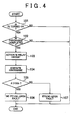
- step 101: YES when the ignition switch 52 is turned on (step 101: YES) and recharge of the capacitor 43 is completed (step 102: YES), the ECU 23 (microcomputer 33) activates the relay circuit 42 (step 103) and then proceeds to step 104.
- step 101: NO the microcomputer 33 does not execute the process in step 102 and the following steps.
- step 102: NO the microcomputer 33 does not execute the process in step 103 and the following steps.
- step 104 the microcomputer 33 outputs the motor control signals Sm for turning on both the FETs 35a and 35c at predetermined duty ratios to the driving circuit 32 to discharge the capacitor 43 (step 104), and then determines whether the voltage difference ⁇ V between both terminals of the relay contact 41 at that time is smaller than the predetermined voltage difference Vth (step 105). Then, when the voltage difference ⁇ V is smaller than the predetermined voltage difference Vth (step 105: YES), the microcomputer 33 determines that the relay contact 41 has no stuck-open fault (step 106), and then ends the process. On the other hand, when the voltage difference ⁇ V is larger than or equal to the predetermined voltage difference Vth (step 105: NO), the microcomputer 33 determines that the relay contact 41 has a stuck-open fault (step 107), and then ends the process.
- the microcomputer 33 deactivates the relay circuit 42 in order to turn off the relay contact 41 in a state where the ignition switch 52 is turned off, and then determines whether there is a fault (stuck-closed fault), in which the relay contact 41 is stuck closed and the relay contact 41 remains turned on, on the basis of whether electric power is supplied to the microcomputer 33.
- the microcomputer 33 deactivates the relay circuit 42 in order to turn off the relay contact 41 in a state where the ignition switch 52 is turned off, and then determines that the relay contact 41 has a stuck-closed fault if electric power is supplied to the microcomputer 33.
- whether electric power is supplied to the microcomputer 33 is determined on the basis of the terminal voltage of a connecting terminal 63 at which the microcomputer 33 is connected to the third power supply path L3. Then, when the stuck-closed fault has been detected, for example, an alarm lamp is lit up to notify the driver of the fault.
- step 201: YES the microcomputer deactivates the relay circuit 42 (step 202), and proceeds to step 203.
- the microcomputer 33 determines that the ignition switch 52 is not turned off (step 201: NO)
- the microcomputer 33 does not execute the process in step 202 and the following steps.
- step 203 the microcomputer 33 determines whether electric power is supplied to the microcomputer 33 (step 203), and, when no electric power is supplied to the microcomputer 33 (step 203: NO), the microcomputer 33 determines that the relay contact 41 has no stuck-closed fault (step 204), and ends the process.
- step 203: NO when electric power is supplied to the microcomputer 33 (step 203: NO), the microcomputer 33 determines that the relay contact 41 has a stuek-closed fault (step 205), and ends the process.
- step 203 the microcomputer 33 determines that the relay contact 41 has no stack-closed fault when no electric power is supplied to the microcomputer 33.
- the relay contact 41 has no stuck-closed fault
- supply of electric power to the microcomputer 33 is interrupted and then the microcomputer 33 stops. Therefore, the microcomputer 33 does not make the above determination.
- the ECU 23 includes the driving circuit 32 that is configured as an H bridge circuit, the microcomputer 33 that controls the operation of the driving circuit 32, the capacitor 43 for stabilizing supply of electric power to the driving circuit 32 and the resistor 51 that is interposed in the second power supply path L2 that bypasses the first power supply path L1 in which the relay contact 41 is interposed.
- the microcomputer 33 activates the relay circuit 42 after the capacitor 43 is precharged via the resistor 51 (second power supply path L2).
- the microcomputer 33 determines whether a stuck-open fault has occurred on the basis of the voltage difference between the terminals of the relay contact 41 at the time when both the FETs 35a and 35c that are connected in series and that constitute the driving circuit 32 are turned on to cause the discharge of the capacitor 43 after the relay circuit 42 is activated.
- the relay contact 41 has a stuck-open fault
- the driving circuit 32 causes the discharge of the capacitor 43 in a state where the capacitor 43 is precharged via the resistor 51
- the capacitor 43-side terminal voltage Vb of the relay contact 41 decreases with a voltage drop caused by the resistor 51, and then a voltage difference ⁇ V occurs between both terminals of the relay contact 41.
- the microcomputer 33 may determine that the relay contact 41 has a stuck-open fault.
- the precharge circuit is not required to have a function of switching between the execution and termination of the precharge, unlike the existing art.
- the capacitor 43 is discharged by turning on both the FETs 35a and 35c that constitute the switching arm 36. Therefore, the discharge circuit is no longer required. Accordingly, it is possible to employ a circuit having a scale smaller than that of the precharge circuit. As a result, it is possible to reduce the number of components and reduce the area of the substrate. This makes it possible to reduce the cost and decrease the failure rate of the EPS 1.
- the microcomputer 33 receives electric power supplied through the third power supply path L3 that is electrically connected via the resistor 51 of the second power supply path L2. Then, the microcomputer 33 determines that the relay contact 41 has a stuck-closed fault when electric power is supplied to the microcomputer 33 after the ignition switch 52 is turned off and the relay circuit 42 is deactivated. With the above configuration, when the relay contact 41 has a stuck-closed fault, electric power is supplied to the microcomputer 33 after the ignition switch 52 is turned off and the relay circuit 42 is deactivated. Thus, the microcomputer 33 may determine that the relay contact 41 has a stuck-closed fault when electric power is supplied to the microcomputer 33 after the ignition switch 52 is turned off and the relay circuit 42 is deactivated.
- the microcomputer 33 limits the duty ratios of the motor control signals Sm that are input in the pair of FETs 35a and 35c at or below the predetermined duty ratio.
- the microcomputer 33 limits the duty ratios of the motor control signals Sm that are input in the pair of FETs 35a and 35c at or below the predetermined duty ratio.
- the microcomputer 33 determines that the relay contact 41 has a stuck-open fault when the voltage difference ⁇ V between both terminals of the relay contact 41 at the time when the capacitor 43 is discharged is larger than or equal to the predetermined voltage difference Vth.
- the microcomputer 33 determines that the relay contact 41 has a stuck-open fault when the voltage difference ⁇ V between both terminals of the relay contact 41 at the time when the capacitor 43 is discharged is larger than or equal to the predetermined voltage difference Vth.
- a brush direct-current motor is employed as the motor 21, and the driving circuit 32 is formed of the two switching arms 36 and 37.
- the aspect of the invention is not limited to the above embodiment.
- a brushless motor that is driven by three-phase driving currents may be employed as the motor 21, the driving circuit 32 may be formed of three switching arms that correspond to the respective phases and that are connected in parallel with one another, and the capacitor 43 may be discharged via only one of these three switching arms.
- the microcomputer 33 determines that the relay contact 41 has a stuck-closed fault when electric power is supplied to the microcomputer 33 after the ignition switch 52 is turned off and the relay circuit 42 is deactivated.
- the aspect of the invention is not limited to this.
- the microcomputer 33 may determine that the relay contact 41 has a stuck-closed fault when electric power is supplied to another electrical component 57 that receives electric power supplied through the third power supply path L3 after the ignition switch 52 is turned off and the relay circuit 42 is deactivated.
- the microcomputer 33 determines whether a stuck-closed fault of the relay contact 41 has occurred when the ECU 23 turns off the ignition switch 52.
- the aspect of the invention is not limited to this.
- the configuration where the microcomputer 33 does not determine whether a stuck-closed fault has occurred may be employed.
- the IG signal Sig that indicates the on/off state of the ignition switch 52 is input from the upper level ECU to the microcomputer 33.
- the IG signal Sig may be input from another element, or the like.
- a sensor that detects driver's operation on the ignition switch may be provided, and an IG signal may be output from the sensor to the microcomputer 33.
- the microcomputer 33 activates the relay circuit 42 after a lapse of the predetermined period of time after the ignition switch 52 is turned on.
- the precharge amount of the capacitor 43 may be detected, and the relay circuit 42 may be activated after the precharge amount is larger than or equal to a predetermined amount at which inrush current does not flow.
- the voltage sensor 61 is provided between the ignition switch 52 and the diode 56 and the voltage sensor 62 is provided between the capacitor 43-side terminal of the relay contact 41 and the coil 47.
- the aspect of the invention is not limited to this. As long as it is possible to detect both terminal voltages Va and Vb of the relay contact 41, voltage sensors may be provided at other locations.
- the duty ratios of the motor control signals Sm are set at or below the predetermined ratio at which a current flowing from the power supply 31 is prohibited from being excessive.
- the aspect of the invention is not limited to this.
- the duty ratios need not be set at or below the predetermined duty ratio.
- the invention is applied to the ECU 23 that controls the operation of the motor 21 that is the driving source of the EPS actuator 22.
- the aspect of the invention is not limited to this.
- the invention may be applied to an ECU that controls the operation of an actuator of a component other than the motor 21 of the EPS actuator 22.
- An ECU (23) of an electric power steering system includes a driving circuit (32) configured as an H bridge circuit; a microcomputer (33) that controls the driving circuit (32); a capacitor (43) for stabilizing electric power that is supplied to the driving circuit (32); and a resistor (51) that is interposed in a second power supply path (L2) that bypasses a first power supply path (L1) in which the relay contact (41) is interposed.
- the microcomputer (33) causes a relay circuit (42) to be activated after the capacitor (43) is charged via the resistor (51) (second power supply path (L2)).
- the microcomputer (33) determines whether a stuck-open fault has occurred on the basis of a voltage difference between terminals of the relay contact (41) at the time when both FETs (35a and 35c) that are connected in series and that constitute the driving circuit (32) are turned on to cause the discharge of the capacitor (43) after the relay circuit (42) is activated.
Landscapes
- Engineering & Computer Science (AREA)
- Chemical & Material Sciences (AREA)
- Combustion & Propulsion (AREA)
- Transportation (AREA)
- Mechanical Engineering (AREA)
- Power Steering Mechanism (AREA)
- Steering Control In Accordance With Driving Conditions (AREA)
Applications Claiming Priority (1)
| Application Number | Priority Date | Filing Date | Title |
|---|---|---|---|
| JP2009218799A JP5444992B2 (ja) | 2009-09-24 | 2009-09-24 | 電動パワーステアリング装置 |
Publications (3)
| Publication Number | Publication Date |
|---|---|
| EP2301822A2 true EP2301822A2 (de) | 2011-03-30 |
| EP2301822A3 EP2301822A3 (de) | 2011-08-24 |
| EP2301822B1 EP2301822B1 (de) | 2013-05-01 |
Family
ID=43243794
Family Applications (1)
| Application Number | Title | Priority Date | Filing Date |
|---|---|---|---|
| EP10178776.0A Not-in-force EP2301822B1 (de) | 2009-09-24 | 2010-09-23 | Elektrisches Servolenksystem |
Country Status (4)
| Country | Link |
|---|---|
| US (1) | US8401738B2 (de) |
| EP (1) | EP2301822B1 (de) |
| JP (1) | JP5444992B2 (de) |
| CN (1) | CN102030030B (de) |
Cited By (2)
| Publication number | Priority date | Publication date | Assignee | Title |
|---|---|---|---|---|
| CN106505739A (zh) * | 2016-01-19 | 2017-03-15 | 南京合智电力科技有限公司 | 一种具有自检功能的控制回路 |
| US20250002073A1 (en) * | 2023-06-29 | 2025-01-02 | Robert Bosch Gmbh | Method for Decelerating a Servomotor of a Steering Device |
Families Citing this family (21)
| Publication number | Priority date | Publication date | Assignee | Title |
|---|---|---|---|---|
| JP5668441B2 (ja) * | 2010-12-07 | 2015-02-12 | 株式会社ジェイテクト | 駆動力配分制御装置 |
| JP5409692B2 (ja) * | 2011-04-18 | 2014-02-05 | 三菱電機株式会社 | 電動パワーステアリング装置 |
| CN102798817B (zh) * | 2011-05-26 | 2015-08-26 | 比亚迪股份有限公司 | 一种继电器故障检测电路及其故障检测方法 |
| JP5265736B2 (ja) * | 2011-07-05 | 2013-08-14 | 富士重工業株式会社 | 充電システム、電動車両、および充電器 |
| JP5888101B2 (ja) * | 2012-05-09 | 2016-03-16 | 株式会社デンソー | 制御装置 |
| KR101457663B1 (ko) * | 2012-05-29 | 2014-11-07 | 주식회사 만도 | 전동식 파워 스티어링 시스템 및 그의 초기 구동 체크 방법 |
| JP6136679B2 (ja) * | 2012-08-09 | 2017-05-31 | 株式会社Gsユアサ | 蓄電装置及び電力経路開閉装置 |
| JP6365725B2 (ja) * | 2012-08-09 | 2018-08-01 | 株式会社Gsユアサ | 蓄電装置及び電力経路開閉装置 |
| JP5973856B2 (ja) * | 2012-09-18 | 2016-08-23 | 日立オートモティブシステムズ株式会社 | 電動パワーステアリング装置および電動パワーステアリング装置の制御装置 |
| JP2014091343A (ja) * | 2012-10-31 | 2014-05-19 | Jtekt Corp | 電動パワーステアリング装置 |
| JP5811081B2 (ja) * | 2012-12-18 | 2015-11-11 | 日本精工株式会社 | 電源リレー制御装置 |
| CN103303250A (zh) * | 2013-05-15 | 2013-09-18 | 苏州震科汽车部件有限公司 | 一种商用车eps转向电机装置 |
| JP5880492B2 (ja) * | 2013-07-03 | 2016-03-09 | 株式会社デンソー | 回転電機制御装置 |
| JP6182385B2 (ja) * | 2013-08-05 | 2017-08-16 | 日立オートモティブシステムズ株式会社 | 電動モータの制御装置 |
| JP5683667B1 (ja) * | 2013-10-11 | 2015-03-11 | 三菱電機株式会社 | 電動式パワーステアリング装置 |
| JP6451192B2 (ja) * | 2014-10-06 | 2019-01-16 | 三菱自動車工業株式会社 | 電動ステアリング装置 |
| KR101647438B1 (ko) * | 2015-04-06 | 2016-08-11 | 주식회사 지니틱스 | 유도성 부하 검출장치 |
| JP7039860B2 (ja) * | 2017-05-11 | 2022-03-23 | 東京電力ホールディングス株式会社 | 電磁接触器の接触不良検出装置 |
| JP7172306B2 (ja) * | 2018-09-03 | 2022-11-16 | 株式会社ジェイテクト | 車両制御装置 |
| CN109850008B (zh) * | 2019-02-25 | 2020-07-28 | 南京航空航天大学 | 一种双电机双电源线控转向系统及其容错控制方法 |
| CN111722104B (zh) * | 2020-06-30 | 2023-10-20 | 潍柴动力股份有限公司 | 一种检测进气加热继电器状态的方法及装置 |
Citations (1)
| Publication number | Priority date | Publication date | Assignee | Title |
|---|---|---|---|---|
| JP2007276706A (ja) | 2006-04-10 | 2007-10-25 | Nsk Ltd | 電動パワーステアリング制御装置 |
Family Cites Families (9)
| Publication number | Priority date | Publication date | Assignee | Title |
|---|---|---|---|---|
| JPH0919003A (ja) * | 1995-06-27 | 1997-01-17 | Honda Motor Co Ltd | 電動車両におけるコンデンサの劣化判定装置 |
| JPH1169881A (ja) * | 1997-08-26 | 1999-03-09 | Toyota Motor Corp | 電動モータ駆動装置 |
| JP3511593B2 (ja) * | 2000-11-10 | 2004-03-29 | 三菱電機株式会社 | 電動パワーステアリング制御装置 |
| JP2002175750A (ja) * | 2000-12-08 | 2002-06-21 | Toyota Motor Corp | リレーの溶着検出装置 |
| JP2002240655A (ja) * | 2001-02-20 | 2002-08-28 | Daihatsu Motor Co Ltd | 車載用モータ制御装置の異常検出装置及び異常検出方法 |
| US6909285B2 (en) * | 2002-09-11 | 2005-06-21 | Visteon Global Technologies, Inc. | Method for detecting failure of a relay |
| JP4352253B2 (ja) * | 2004-01-29 | 2009-10-28 | 株式会社デンソー | 車両の伝達比可変操舵装置 |
| JP4111191B2 (ja) * | 2004-12-28 | 2008-07-02 | 日産自動車株式会社 | 車両用操舵装置 |
| JP4631928B2 (ja) * | 2008-05-12 | 2011-02-16 | トヨタ自動車株式会社 | 車両のステアリング装置 |
-
2009
- 2009-09-24 JP JP2009218799A patent/JP5444992B2/ja not_active Expired - Fee Related
-
2010
- 2010-09-19 CN CN201010289799.2A patent/CN102030030B/zh not_active Expired - Fee Related
- 2010-09-20 US US12/885,780 patent/US8401738B2/en not_active Expired - Fee Related
- 2010-09-23 EP EP10178776.0A patent/EP2301822B1/de not_active Not-in-force
Patent Citations (1)
| Publication number | Priority date | Publication date | Assignee | Title |
|---|---|---|---|---|
| JP2007276706A (ja) | 2006-04-10 | 2007-10-25 | Nsk Ltd | 電動パワーステアリング制御装置 |
Cited By (2)
| Publication number | Priority date | Publication date | Assignee | Title |
|---|---|---|---|---|
| CN106505739A (zh) * | 2016-01-19 | 2017-03-15 | 南京合智电力科技有限公司 | 一种具有自检功能的控制回路 |
| US20250002073A1 (en) * | 2023-06-29 | 2025-01-02 | Robert Bosch Gmbh | Method for Decelerating a Servomotor of a Steering Device |
Also Published As
| Publication number | Publication date |
|---|---|
| US8401738B2 (en) | 2013-03-19 |
| CN102030030A (zh) | 2011-04-27 |
| JP5444992B2 (ja) | 2014-03-19 |
| US20110071730A1 (en) | 2011-03-24 |
| EP2301822A3 (de) | 2011-08-24 |
| EP2301822B1 (de) | 2013-05-01 |
| CN102030030B (zh) | 2014-10-01 |
| JP2011068178A (ja) | 2011-04-07 |
Similar Documents
| Publication | Publication Date | Title |
|---|---|---|
| US8401738B2 (en) | Electric power steering system | |
| US8786228B2 (en) | Controller for electrical power steering apparatus | |
| US20160028336A1 (en) | Control apparatus for electric motor and control method for electric motor | |
| JP5151471B2 (ja) | 電動パワーステアリング装置 | |
| EP2328268A1 (de) | Motorsteuerungsvorrichtung und elektrische servolenkung | |
| JP2009154758A (ja) | 電動パワーステアリング装置 | |
| US9906174B2 (en) | Power steering device and control device for power steering device | |
| US6995567B2 (en) | Failure detection system for electric power steering system | |
| CN107585118B (zh) | 与外部装置共享电池的系统 | |
| JP4882467B2 (ja) | 電動パワーステアリング制御装置 | |
| JP4366712B2 (ja) | モータ駆動装置およびモータ駆動装置の故障検出方法 | |
| JP2020039200A (ja) | 車両制御装置 | |
| US9143075B2 (en) | Drive control device and drive control method for motor | |
| JP6586800B2 (ja) | モータ制御装置 | |
| US20080217095A1 (en) | Limiting Device for Limiting Relay Welding and Motor Driving Apparatus | |
| JP5402068B2 (ja) | モータ制御装置 | |
| JP4482927B2 (ja) | 昇圧装置 | |
| JP5407935B2 (ja) | 電動パワーステアリング装置 | |
| JP2011213255A (ja) | 電動パワーステアリング装置 | |
| JP7022319B2 (ja) | 電源システム | |
| JPH11152049A (ja) | 電動パワーステアリング装置の制御装置 | |
| JP2007022413A (ja) | 電動パワーステアリング装置 | |
| JP2019137374A (ja) | 電源装置および電源システム |
Legal Events
| Date | Code | Title | Description |
|---|---|---|---|
| PUAI | Public reference made under article 153(3) epc to a published international application that has entered the european phase |
Free format text: ORIGINAL CODE: 0009012 |
|
| AK | Designated contracting states |
Kind code of ref document: A2 Designated state(s): AL AT BE BG CH CY CZ DE DK EE ES FI FR GB GR HR HU IE IS IT LI LT LU LV MC MK MT NL NO PL PT RO SE SI SK SM TR |
|
| AX | Request for extension of the european patent |
Extension state: BA ME RS |
|
| PUAL | Search report despatched |
Free format text: ORIGINAL CODE: 0009013 |
|
| AK | Designated contracting states |
Kind code of ref document: A3 Designated state(s): AL AT BE BG CH CY CZ DE DK EE ES FI FR GB GR HR HU IE IS IT LI LT LU LV MC MK MT NL NO PL PT RO SE SI SK SM TR |
|
| AX | Request for extension of the european patent |
Extension state: BA ME RS |
|
| RIC1 | Information provided on ipc code assigned before grant |
Ipc: B62D 5/04 20060101AFI20110715BHEP Ipc: G01R 31/327 20060101ALI20110715BHEP |
|
| 17P | Request for examination filed |
Effective date: 20120131 |
|
| GRAP | Despatch of communication of intention to grant a patent |
Free format text: ORIGINAL CODE: EPIDOSNIGR1 |
|
| GRAS | Grant fee paid |
Free format text: ORIGINAL CODE: EPIDOSNIGR3 |
|
| GRAA | (expected) grant |
Free format text: ORIGINAL CODE: 0009210 |
|
| AK | Designated contracting states |
Kind code of ref document: B1 Designated state(s): AL AT BE BG CH CY CZ DE DK EE ES FI FR GB GR HR HU IE IS IT LI LT LU LV MC MK MT NL NO PL PT RO SE SI SK SM TR |
|
| REG | Reference to a national code |
Ref country code: GB Ref legal event code: FG4D |
|
| REG | Reference to a national code |
Ref country code: AT Ref legal event code: REF Ref document number: 609733 Country of ref document: AT Kind code of ref document: T Effective date: 20130515 Ref country code: CH Ref legal event code: EP |
|
| REG | Reference to a national code |
Ref country code: IE Ref legal event code: FG4D |
|
| REG | Reference to a national code |
Ref country code: DE Ref legal event code: R096 Ref document number: 602010006625 Country of ref document: DE Effective date: 20130627 |
|
| REG | Reference to a national code |
Ref country code: AT Ref legal event code: MK05 Ref document number: 609733 Country of ref document: AT Kind code of ref document: T Effective date: 20130501 |
|
| REG | Reference to a national code |
Ref country code: NL Ref legal event code: VDEP Effective date: 20130501 |
|
| REG | Reference to a national code |
Ref country code: LT Ref legal event code: MG4D |
|
| PG25 | Lapsed in a contracting state [announced via postgrant information from national office to epo] |
Ref country code: SI Free format text: LAPSE BECAUSE OF FAILURE TO SUBMIT A TRANSLATION OF THE DESCRIPTION OR TO PAY THE FEE WITHIN THE PRESCRIBED TIME-LIMIT Effective date: 20130501 Ref country code: PT Free format text: LAPSE BECAUSE OF FAILURE TO SUBMIT A TRANSLATION OF THE DESCRIPTION OR TO PAY THE FEE WITHIN THE PRESCRIBED TIME-LIMIT Effective date: 20130902 Ref country code: ES Free format text: LAPSE BECAUSE OF FAILURE TO SUBMIT A TRANSLATION OF THE DESCRIPTION OR TO PAY THE FEE WITHIN THE PRESCRIBED TIME-LIMIT Effective date: 20130812 Ref country code: LT Free format text: LAPSE BECAUSE OF FAILURE TO SUBMIT A TRANSLATION OF THE DESCRIPTION OR TO PAY THE FEE WITHIN THE PRESCRIBED TIME-LIMIT Effective date: 20130501 Ref country code: IS Free format text: LAPSE BECAUSE OF FAILURE TO SUBMIT A TRANSLATION OF THE DESCRIPTION OR TO PAY THE FEE WITHIN THE PRESCRIBED TIME-LIMIT Effective date: 20130901 Ref country code: GR Free format text: LAPSE BECAUSE OF FAILURE TO SUBMIT A TRANSLATION OF THE DESCRIPTION OR TO PAY THE FEE WITHIN THE PRESCRIBED TIME-LIMIT Effective date: 20130802 Ref country code: SE Free format text: LAPSE BECAUSE OF FAILURE TO SUBMIT A TRANSLATION OF THE DESCRIPTION OR TO PAY THE FEE WITHIN THE PRESCRIBED TIME-LIMIT Effective date: 20130501 Ref country code: NO Free format text: LAPSE BECAUSE OF FAILURE TO SUBMIT A TRANSLATION OF THE DESCRIPTION OR TO PAY THE FEE WITHIN THE PRESCRIBED TIME-LIMIT Effective date: 20130801 Ref country code: FI Free format text: LAPSE BECAUSE OF FAILURE TO SUBMIT A TRANSLATION OF THE DESCRIPTION OR TO PAY THE FEE WITHIN THE PRESCRIBED TIME-LIMIT Effective date: 20130501 Ref country code: AT Free format text: LAPSE BECAUSE OF FAILURE TO SUBMIT A TRANSLATION OF THE DESCRIPTION OR TO PAY THE FEE WITHIN THE PRESCRIBED TIME-LIMIT Effective date: 20130501 |
|
| PG25 | Lapsed in a contracting state [announced via postgrant information from national office to epo] |
Ref country code: HR Free format text: LAPSE BECAUSE OF FAILURE TO SUBMIT A TRANSLATION OF THE DESCRIPTION OR TO PAY THE FEE WITHIN THE PRESCRIBED TIME-LIMIT Effective date: 20130501 Ref country code: BG Free format text: LAPSE BECAUSE OF FAILURE TO SUBMIT A TRANSLATION OF THE DESCRIPTION OR TO PAY THE FEE WITHIN THE PRESCRIBED TIME-LIMIT Effective date: 20130801 Ref country code: PL Free format text: LAPSE BECAUSE OF FAILURE TO SUBMIT A TRANSLATION OF THE DESCRIPTION OR TO PAY THE FEE WITHIN THE PRESCRIBED TIME-LIMIT Effective date: 20130501 Ref country code: CY Free format text: LAPSE BECAUSE OF FAILURE TO SUBMIT A TRANSLATION OF THE DESCRIPTION OR TO PAY THE FEE WITHIN THE PRESCRIBED TIME-LIMIT Effective date: 20130501 |
|
| PG25 | Lapsed in a contracting state [announced via postgrant information from national office to epo] |
Ref country code: LV Free format text: LAPSE BECAUSE OF FAILURE TO SUBMIT A TRANSLATION OF THE DESCRIPTION OR TO PAY THE FEE WITHIN THE PRESCRIBED TIME-LIMIT Effective date: 20130501 |
|
| PG25 | Lapsed in a contracting state [announced via postgrant information from national office to epo] |
Ref country code: DK Free format text: LAPSE BECAUSE OF FAILURE TO SUBMIT A TRANSLATION OF THE DESCRIPTION OR TO PAY THE FEE WITHIN THE PRESCRIBED TIME-LIMIT Effective date: 20130501 Ref country code: CZ Free format text: LAPSE BECAUSE OF FAILURE TO SUBMIT A TRANSLATION OF THE DESCRIPTION OR TO PAY THE FEE WITHIN THE PRESCRIBED TIME-LIMIT Effective date: 20130501 Ref country code: SK Free format text: LAPSE BECAUSE OF FAILURE TO SUBMIT A TRANSLATION OF THE DESCRIPTION OR TO PAY THE FEE WITHIN THE PRESCRIBED TIME-LIMIT Effective date: 20130501 Ref country code: EE Free format text: LAPSE BECAUSE OF FAILURE TO SUBMIT A TRANSLATION OF THE DESCRIPTION OR TO PAY THE FEE WITHIN THE PRESCRIBED TIME-LIMIT Effective date: 20130501 Ref country code: BE Free format text: LAPSE BECAUSE OF FAILURE TO SUBMIT A TRANSLATION OF THE DESCRIPTION OR TO PAY THE FEE WITHIN THE PRESCRIBED TIME-LIMIT Effective date: 20130501 |
|
| PG25 | Lapsed in a contracting state [announced via postgrant information from national office to epo] |
Ref country code: IT Free format text: LAPSE BECAUSE OF FAILURE TO SUBMIT A TRANSLATION OF THE DESCRIPTION OR TO PAY THE FEE WITHIN THE PRESCRIBED TIME-LIMIT Effective date: 20130501 Ref country code: RO Free format text: LAPSE BECAUSE OF FAILURE TO SUBMIT A TRANSLATION OF THE DESCRIPTION OR TO PAY THE FEE WITHIN THE PRESCRIBED TIME-LIMIT Effective date: 20130501 Ref country code: NL Free format text: LAPSE BECAUSE OF FAILURE TO SUBMIT A TRANSLATION OF THE DESCRIPTION OR TO PAY THE FEE WITHIN THE PRESCRIBED TIME-LIMIT Effective date: 20130501 |
|
| PLBE | No opposition filed within time limit |
Free format text: ORIGINAL CODE: 0009261 |
|
| STAA | Information on the status of an ep patent application or granted ep patent |
Free format text: STATUS: NO OPPOSITION FILED WITHIN TIME LIMIT |
|
| 26N | No opposition filed |
Effective date: 20140204 |
|
| PG25 | Lapsed in a contracting state [announced via postgrant information from national office to epo] |
Ref country code: MC Free format text: LAPSE BECAUSE OF FAILURE TO SUBMIT A TRANSLATION OF THE DESCRIPTION OR TO PAY THE FEE WITHIN THE PRESCRIBED TIME-LIMIT Effective date: 20130501 |
|
| REG | Reference to a national code |
Ref country code: DE Ref legal event code: R097 Ref document number: 602010006625 Country of ref document: DE Effective date: 20140204 |
|
| REG | Reference to a national code |
Ref country code: IE Ref legal event code: MM4A |
|
| PG25 | Lapsed in a contracting state [announced via postgrant information from national office to epo] |
Ref country code: IE Free format text: LAPSE BECAUSE OF NON-PAYMENT OF DUE FEES Effective date: 20130923 |
|
| REG | Reference to a national code |
Ref country code: CH Ref legal event code: PL |
|
| GBPC | Gb: european patent ceased through non-payment of renewal fee |
Effective date: 20140923 |
|
| PG25 | Lapsed in a contracting state [announced via postgrant information from national office to epo] |
Ref country code: SM Free format text: LAPSE BECAUSE OF FAILURE TO SUBMIT A TRANSLATION OF THE DESCRIPTION OR TO PAY THE FEE WITHIN THE PRESCRIBED TIME-LIMIT Effective date: 20130501 |
|
| PG25 | Lapsed in a contracting state [announced via postgrant information from national office to epo] |
Ref country code: MT Free format text: LAPSE BECAUSE OF FAILURE TO SUBMIT A TRANSLATION OF THE DESCRIPTION OR TO PAY THE FEE WITHIN THE PRESCRIBED TIME-LIMIT Effective date: 20130501 Ref country code: TR Free format text: LAPSE BECAUSE OF FAILURE TO SUBMIT A TRANSLATION OF THE DESCRIPTION OR TO PAY THE FEE WITHIN THE PRESCRIBED TIME-LIMIT Effective date: 20130501 |
|
| PG25 | Lapsed in a contracting state [announced via postgrant information from national office to epo] |
Ref country code: HU Free format text: LAPSE BECAUSE OF FAILURE TO SUBMIT A TRANSLATION OF THE DESCRIPTION OR TO PAY THE FEE WITHIN THE PRESCRIBED TIME-LIMIT; INVALID AB INITIO Effective date: 20100923 Ref country code: GB Free format text: LAPSE BECAUSE OF NON-PAYMENT OF DUE FEES Effective date: 20140923 Ref country code: LU Free format text: LAPSE BECAUSE OF NON-PAYMENT OF DUE FEES Effective date: 20130923 Ref country code: CH Free format text: LAPSE BECAUSE OF NON-PAYMENT OF DUE FEES Effective date: 20140930 Ref country code: LI Free format text: LAPSE BECAUSE OF NON-PAYMENT OF DUE FEES Effective date: 20140930 Ref country code: MK Free format text: LAPSE BECAUSE OF FAILURE TO SUBMIT A TRANSLATION OF THE DESCRIPTION OR TO PAY THE FEE WITHIN THE PRESCRIBED TIME-LIMIT Effective date: 20130501 |
|
| REG | Reference to a national code |
Ref country code: FR Ref legal event code: PLFP Year of fee payment: 7 |
|
| PGFP | Annual fee paid to national office [announced via postgrant information from national office to epo] |
Ref country code: DE Payment date: 20160920 Year of fee payment: 7 |
|
| PGFP | Annual fee paid to national office [announced via postgrant information from national office to epo] |
Ref country code: FR Payment date: 20160816 Year of fee payment: 7 |
|
| REG | Reference to a national code |
Ref country code: DE Ref legal event code: R119 Ref document number: 602010006625 Country of ref document: DE |
|
| REG | Reference to a national code |
Ref country code: FR Ref legal event code: ST Effective date: 20180531 |
|
| PG25 | Lapsed in a contracting state [announced via postgrant information from national office to epo] |
Ref country code: DE Free format text: LAPSE BECAUSE OF NON-PAYMENT OF DUE FEES Effective date: 20180404 |
|
| PG25 | Lapsed in a contracting state [announced via postgrant information from national office to epo] |
Ref country code: FR Free format text: LAPSE BECAUSE OF NON-PAYMENT OF DUE FEES Effective date: 20171002 |
|
| PG25 | Lapsed in a contracting state [announced via postgrant information from national office to epo] |
Ref country code: AL Free format text: LAPSE BECAUSE OF FAILURE TO SUBMIT A TRANSLATION OF THE DESCRIPTION OR TO PAY THE FEE WITHIN THE PRESCRIBED TIME-LIMIT Effective date: 20130501 |