EP2301836A2 - Bojenvorrichtung mit programmiertem Auftrieb - Google Patents
Bojenvorrichtung mit programmiertem Auftrieb Download PDFInfo
- Publication number
- EP2301836A2 EP2301836A2 EP10177770A EP10177770A EP2301836A2 EP 2301836 A2 EP2301836 A2 EP 2301836A2 EP 10177770 A EP10177770 A EP 10177770A EP 10177770 A EP10177770 A EP 10177770A EP 2301836 A2 EP2301836 A2 EP 2301836A2
- Authority
- EP
- European Patent Office
- Prior art keywords
- buoy
- electromagnet
- support
- immersed
- open position
- Prior art date
- Legal status (The legal status is an assumption and is not a legal conclusion. Google has not performed a legal analysis and makes no representation as to the accuracy of the status listed.)
- Granted
Links
Images



Classifications
-
- B—PERFORMING OPERATIONS; TRANSPORTING
- B63—SHIPS OR OTHER WATERBORNE VESSELS; RELATED EQUIPMENT
- B63B—SHIPS OR OTHER WATERBORNE VESSELS; EQUIPMENT FOR SHIPPING
- B63B22/00—Buoys
- B63B22/04—Fixations or other anchoring arrangements
- B63B22/06—Fixations or other anchoring arrangements with means to cause the buoy to surface in response to a transmitted signal
-
- A—HUMAN NECESSITIES
- A01—AGRICULTURE; FORESTRY; ANIMAL HUSBANDRY; HUNTING; TRAPPING; FISHING
- A01K—ANIMAL HUSBANDRY; AVICULTURE; APICULTURE; PISCICULTURE; FISHING; REARING OR BREEDING ANIMALS, NOT OTHERWISE PROVIDED FOR; NEW BREEDS OF ANIMALS
- A01K69/00—Stationary catching devices
-
- A—HUMAN NECESSITIES
- A01—AGRICULTURE; FORESTRY; ANIMAL HUSBANDRY; HUNTING; TRAPPING; FISHING
- A01K—ANIMAL HUSBANDRY; AVICULTURE; APICULTURE; PISCICULTURE; FISHING; REARING OR BREEDING ANIMALS, NOT OTHERWISE PROVIDED FOR; NEW BREEDS OF ANIMALS
- A01K69/00—Stationary catching devices
- A01K69/06—Traps
- A01K69/08—Rigid traps, e.g. lobster pots
-
- A—HUMAN NECESSITIES
- A01—AGRICULTURE; FORESTRY; ANIMAL HUSBANDRY; HUNTING; TRAPPING; FISHING
- A01K—ANIMAL HUSBANDRY; AVICULTURE; APICULTURE; PISCICULTURE; FISHING; REARING OR BREEDING ANIMALS, NOT OTHERWISE PROVIDED FOR; NEW BREEDS OF ANIMALS
- A01K91/00—Lines
- A01K91/18—Trotlines, longlines; Accessories therefor, e.g. baiting devices, lifters or setting reelers
Definitions
- the field of the invention is that of devices for tracking submerged objects such as fishing racks.
- the invention relates to a buoy device with controlled lift.
- Tracking devices can be implemented to signal temporarily from the surface of a body of water the presence of an object that is immersed therein.
- Such devices conventionally comprise a buoy connected to an object to be immersed by means of a tip and means for reversibly holding the buoy close to this object.
- These means comprise a permanent magnet integral with the buoy and an electromagnet secured to a support intended to be secured to the object to be immersed, these two magnets being provided to cooperate.
- the electromagnet When the object is thrown into the body of water, the electromagnet is activated so that the buoy is kept close to the object. This one is not then identifiable from the surface of the body of water.
- the electromagnet is deactivated remotely by the owner of the object so that the buoy detaches and rises to the surface of the body of water.
- This technique can for example allow a fisherman to immerse traps without these being spotted by malicious people who would steal them.
- the recovery of the trap can only be carried out after it has been made visible from the surface of the body of water by its owner.
- This technique is effective in that it can temporarily hide an object immersed in a body of water, for example a locker of water. fishing, and that it can be located and stolen by a malicious person. It nevertheless has some disadvantages.
- the electromagnet and the permanent magnet tend to become progressively clogged with the use of the device during the phases in which they are distant from each other. It often happens that dust, sand, mud ... are deposited on the surface of the electromagnet and the permanent magnet. It also happens that these elements receive shocks during the handling of the device. As a result, the attraction force imparted by the electromagnet to the permanent magnet to keep the buoy integral with the immersed object decreases with time. This effort can be so diminished that it no longer allows to effectively maintain the buoy secured to the object. This can then detach from it inadvertently for example under the effect of the currents and eddies of the water and up to the surface. The submerged object then becomes identifiable by anyone and vulnerable so that it can be reassembled and stolen or damaged, or when it is a fishing record, its content may for example be emptied.
- the electromagnet and the permanent magnet are subject to corrosion. They deteriorate well in time. This phenomenon is accelerated when such a device is implemented at sea.
- the buoy does not rise to the surface even if the user requires it.
- control means that briefly inhibit the attraction force impressed by the electromagnet to the permanent magnet, after which the electromagnet covers its attraction capabilities.
- the buoy whose density is lower than that of the water in which it is immersed, detaches from the immersed object and rises to the surface.
- the buoy does not have time to detach from the immersed object between the moment at which the electromagnet loses its attraction and the one to which it covers them. In in this case, the buoy does not rise to the surface so that the user can not locate the location of its immersed object in order to reassemble it.
- the invention particularly aims to overcome these disadvantages of the prior art.
- an object of the invention is to provide, in at least one embodiment, a buoy device with controlled lift in which the buoy is reversibly secured to a support by the implementation of means of electromagnetic attraction that are reliable.
- the invention aims, in at least one embodiment, to implement such a device which avoids the one hand that the buoy inadvertently rises to the surface and secondly that it is kept immersed even if a user requires its ascent.
- the invention also aims, in at least one embodiment, to provide such a technique that allows to preserve over time the attraction capabilities of the electromagnetic attraction means.
- the invention thus aims to propose, in at least one embodiment, such a technique which leads to limiting the corrosion of the electromagnetic attraction means.
- the invention also aims to propose, in at least one embodiment of the invention, such a technique which leads to limit the fouling of the electromagnetic attraction means.
- An object of the invention is still to provide, in at least one embodiment, such a technique which is simple and relatively economical to implement and maintain.
- a controlled buoy device including a buoy intended to be connected reversibly to a submergible support by means of an electromagnet and a polar plate respectively integral with said buoy or said support, and means for deactivating said electromagnet, said support being integral with an object to be immersed.
- such a device comprises means for protecting said electromagnet and said polar plate when said buoy is remote from said support, said protection means comprising a first and a second trapdoor movable between a closed position in which they respectively protect said polar plate and said electromagnet and an open position in which said electromagnet and said pole plate can be brought into contact.
- the invention is based on a completely original approach that consists of implementing elements that protect the electromagnet and the polar plate when they are not in contact. This prevents clogging of their surface, their corrosion, and maintains the magnetic attraction of the electromagnet.
- the implementation of the invention thus contributes to preventing the buoy inadvertently rising to the surface and that it is kept submerged even when a user requires its ascent.
- said protection means are automatic return.
- the protection means are automatically placed in their position in which they protect the electromagnet and against the plate (or polar plate). This increases the reliability of the device by ensuring that the magnetic elements are properly protected.
- said electromagnet is of the ejector type.
- An electromagnet of this type incorporates a piston member that protrudes from the surface of the electromagnet when it is deactivated.
- the electromagnet when it is deactivated, it loses on the one hand its magnetic attraction and on the other hand the ejector protrudes on its surface. This ensures that the buoy is peeled off its support and has time to initiate its recovery to the surface before the electromagnet covers its magnetic attraction capabilities.
- said electromagnet and / or said polar plate are made of stainless steel.
- elastic return means act on said first door to maintain it in said closed position.
- a device according to the invention preferably comprises means for maintaining said second hatch in said open position.
- said holding means are provided for releasing said second door when said buoy is brought closer to said support, said second door then being held in the open position by said buoy.
- the second hatch is unlocked and held in the open position by the buoy so that it will automatically go into its closed position as soon as the buoy is will detach from its support.
- said deactivation means are of the pulse type or programmable.
- they When they are programmable, they may for example include a clock that can be adjusted by a user to control the raising of the buoy at a given date and time. When they are pulse, they may for example include a transmitter that will transmit a signal controlling the ascent of the buoy as soon as a user orders.
- said object carries secure descent means.
- a second buoy is attached to an end of an end connected to said object by securing means provided to break if it is attempted to raise said object by pulling on said end.
- the immersed object can thus be identified from the surface of the body of water without being able to be brought to the surface by a malicious person.
- the general principle of the invention is based on the implementation, within a controlled buoy buoy device in which the buoy is reversibly secured to a support by the implementation of electromagnetic attraction means elements that protect these electromagnetic attraction means when they are not in contact.
- the implementation of the invention therefore contributes to prevent the buoy inadvertently rising to the surface and that it is kept submerged even when a user requires its ascent.
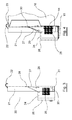
- Such buoy 10 comprises a central axis 11, each end of which is integral with a sidewall 12.
- the buoy 10 thus constitutes a coil around which can be wound an end 38. It is made of a plastic material and has a density less than that of water so that it can float. In variants, it may be made of other materials provided that it can float.
- flanks 12 are of substantially quadrangular shape and have four flat faces 13.
- One of the flat faces 13 of one of the flanks 12 carries a counter plate 14 projecting on its surface.
- This against-plate 14 also called polar plate, is made of a magnetized stainless steel.
- This first hatch 15 constitutes a means of protecting the polar plate 14.
- Elastic return means which comprise in this embodiment a torsion spring, tend to place and hold the first hatch 15 in its closed position.
- the buoy 10 is traversed by a bore 16 along its main axis and one of the sides of one of its flanks 12 carries a handle 18. It is thus possible to wrap the tip 38 around the buoy 10 by making cooperate its drilling 16 with an axis about which it can be rotated by means of the handle 18.
- Such a support 20 comprises a plate 21 against which the buoy 10 is intended to be reversibly secured.
- the plate 21 carries a hook 22 projecting on its surface. This hook 22 is intended to cooperate with a slot 23 provided for this purpose on one side of the sidewall 12 opposite to the sidewall 12 carrying the counterplate 14 of the buoy 10.
- the plate 21 defines a housing 24 inside which are placed an electromagnet 25, means for deactivating the electromagnet 25, and supply means such as a battery.
- the deactivation means comprise a clock connected to an automaton capable of acting on the electromagnet 25 so as to momentarily inhibit its magnetic attraction.
- the electromagnet 25 is of the ejector type.
- a removable cover 26 provides access to the components placed in the sealed housing 24 for example to carry out maintenance.
- the flap 27 may consist of a spring blade naturally resuming its retracted position.
- An abutment 29 protrudes from the surface of the flap 27. It also projects on the surface of the plate 21 when the flap 27 occupies its retracted position.
- the second hatch 30 is held in its closed position supported by gravity against a stop 31 formed in the plate 21. When placed in its open position, it is held in abutment against the stop 29.
- the support 20 is intended to be secured to an object to be immersed. In a variant, it may be constituted by the object to be immersed in itself.
- a remote control allows a user to remotely program the clock.
- the user can choose the date and time at which the clock will act on the controller to momentarily stop the magnetic attraction of the electromagnet 25.
- the remote control can remotely control several devices according to the invention.
- a device according to the invention is used to temporarily signal from the surface of a body of water the presence of an object immersed therein, such as a fishing rack 40.
- the support 20 is secured to one of the sides of the fishing rack 40 so that the electromagnet 25 is directed outwards.
- the second hatch 30 is manually moved from its closed position to its open position in which it is held in abutment against the stop 29.
- the first hatch 15 is moved manually from its closed position to its open position.
- the buoy 10 is then brought closer to its support 20 so that the slit 23 cooperates with the hook 22 and the counterplate 14 co-operates with the electromagnet 25.
- the buoy 10 is then reversibly secured to its support 20.
- the flank 12 which is secured against the plate 14 supports on the stop 29 so as to release the second hatch 30 which is held in its partially open position in abutment against the flank 12 or against counterplate 14.
- the end 38 wound around the buoy 10 has an end secured to the buoy 10 and a free end.
- the free end is fixed to the rack 40 or to the support 20.
- the rack 40 can then be immersed in a body of water by being thrown overboard of a boat 39.
- These secure descent means comprise a hook 31 integral with a ramp 32 inclined relative to the upper surface of the rack 32.
- the hook 31 and the ramp 32 are integral with the upper face of the rack 40.
- the ramp 32 may not be implemented.
- the outline of the hook 31 will be substantially identical to that of the ramp 32.
- the ramp may consist of a stainless metal plate intended to be secured to the upper surface of a rack 40.
- the hook 31 is inserted into a loop 34 secured to one end of a tip 33.
- the locker 40 is then passed overboard and then progressively lowered by a user to the bottom of the body of water by means of the end 33.
- the rack 40 rests at the bottom of the body of water, the user continues to unwind the end 33.
- the loop 34 down along the ramp 32 and separates from the hook 31. The user can then go up the end 33 leaving at the bottom the locker 40.
- the bottom of the rack 40 may have a convex shape so as to form another secure descent means. If during its descent, the bottom of the rack 40 is not horizontal, there is a risk that it is deposited on one of its lateral sides, which can affect the rise of the buoy 10 Because the bottom is convex, if the locker 40 is placed on one of its bottom edges and not directly on its bottom, it will naturally tumble so that the lifted buoy device is placed on one end. of the lateral sides of the bin 40 resting at the bottom of the body of water.
- the submerged bin 40 is not detectable from the surface of the body of water in which it is submerged because the buoy 10 remains secured to the support 20 fixed to the bin 40.
- the bin 40 immersed can be identified by means of a second buoy 35 which includes for example the registration of the boat 39 owner.
- This second buoy 35 is fixed at one end of an end 36 which is connected to the rack 40 by securing means 37 provided to break if it is plausible to raise the rack 40 by pulling on tip 36.
- the user schedules the date and time at which he plans to remount his locker 40.
- the clock acts on the automaton such that the magnetic attraction power of the electromagnet is momentarily inhibited and its ejector, which is in the form of a piston, is moved towards the counterplate 14 before the electromagnet 25 covers its magnetic attraction capacity.
- the counterplate 14 is thus detached from the electromagnet 25 and the buoy 10 rises gradually to the surface of the body of water by unwinding the end 38.
- the plate 30 slides under the effect of gravity in its closed position in which it protects the electromagnet 25.
- Reminder means could be implemented in a variant to ensure the return the second hatch 30 in its closed position.
- the first hatch 15 passes into its closed position in which it protects the counterplate 14.
- buoy 10 Once buoy 10 is on the surface (see dotted line figure 5 ), the user can locate the location of his locker 40 and pull the end 38 secured to the buoy 10 to go up to the surface.
- the user can fasten an "L" -shaped pin 41 to the upper face of his rack 40 and insert it into the bore 16 of the buoy 10 in order to wind the tip 38 around it in the same direction. rotating in the handle 18. It can then again placed the buoy 10 on its support 20 so that the rack is ready to be dropped.
- the means for deactivating the electromagnet 25 may comprise a transmitter and a receiver instead of the clock.
- a transmitter placed for example under the hull of the boat 40 of the user or in a remote control can send a signal, for example ultrasound, to a receiver placed in the support 20, which will act on the
- the frequency of the emitted signal can be adjusted to avoid interference with other devices and theft by other owners of equivalent devices.
- a device according to the invention may be implemented to allow to report temporarily from the surface of a body of water the presence of any immersed objects.
- objects may for example be a ballast 44 connected to a fishing net 42 or to a line 43.
- This ballast 44 may have a convex bottom surface to ensure that the controlled buoy device lifts it implements be placed correctly.
- secure descent means comprise a hook 31 integral with a ramp 32 inclined relative to the upper surface of the ballast 44.
- the hook 31 and the ramp 32 are integral with a flat upper face 70 formed on the surface. of ballast 44.
- the outline of the rack 40 may comprise a curved face towards the inside of the rack 40 so as to define an inner housing accessible from the outside and able to receive a device according to the invention so that it is protected by the bin when immersed.
- the electromagnet and the deactivation means may be integrated into the buoy and the counterplate may be integral with the support.
Landscapes
- Life Sciences & Earth Sciences (AREA)
- Environmental Sciences (AREA)
- Animal Husbandry (AREA)
- Biodiversity & Conservation Biology (AREA)
- Chemical & Material Sciences (AREA)
- Engineering & Computer Science (AREA)
- Combustion & Propulsion (AREA)
- Mechanical Engineering (AREA)
- Ocean & Marine Engineering (AREA)
- Control Of Position, Course, Altitude, Or Attitude Of Moving Bodies (AREA)
Applications Claiming Priority (2)
| Application Number | Priority Date | Filing Date | Title |
|---|---|---|---|
| FR0904487A FR2950316A1 (fr) | 2009-09-21 | 2009-09-21 | Trappes de fermeture manuelle ou automatique pour protection des elements ou dispositifs d'hadhesion fixes sur une bouee immergee et/ou son support ou son orin |
| FR1053689A FR2950318A1 (fr) | 2009-09-21 | 2010-05-11 | Dispositif de bouee a remontee programmee |
Publications (3)
| Publication Number | Publication Date |
|---|---|
| EP2301836A2 true EP2301836A2 (de) | 2011-03-30 |
| EP2301836A3 EP2301836A3 (de) | 2011-05-04 |
| EP2301836B1 EP2301836B1 (de) | 2013-03-20 |
Family
ID=43128326
Family Applications (1)
| Application Number | Title | Priority Date | Filing Date |
|---|---|---|---|
| EP10177770A Not-in-force EP2301836B1 (de) | 2009-09-21 | 2010-09-21 | Bojenvorrichtung mit programmiertem Auftrieb |
Country Status (2)
| Country | Link |
|---|---|
| EP (1) | EP2301836B1 (de) |
| FR (1) | FR2950318A1 (de) |
Families Citing this family (1)
| Publication number | Priority date | Publication date | Assignee | Title |
|---|---|---|---|---|
| FR3063711B1 (fr) | 2017-03-09 | 2021-09-10 | Jose Vicente | Systeme de liberation d'une bouee a l'aide d'une telecommande emettant un signal ultrasonore porteur d'un code |
Family Cites Families (3)
| Publication number | Priority date | Publication date | Assignee | Title |
|---|---|---|---|---|
| US3858166A (en) * | 1973-12-26 | 1974-12-31 | Briddell C | Recoverable underwater acoustic beacon |
| US5100353A (en) * | 1990-10-15 | 1992-03-31 | The United States Of America As Represented By The Secretary Of The Navy | Electromagnetic marker float release |
| US7534152B1 (en) * | 2006-03-15 | 2009-05-19 | Cory Lloyd | Underwater float release system |
-
2010
- 2010-05-11 FR FR1053689A patent/FR2950318A1/fr not_active Withdrawn
- 2010-09-21 EP EP10177770A patent/EP2301836B1/de not_active Not-in-force
Also Published As
| Publication number | Publication date |
|---|---|
| EP2301836A3 (de) | 2011-05-04 |
| EP2301836B1 (de) | 2013-03-20 |
| FR2950318A1 (fr) | 2011-03-25 |
Similar Documents
| Publication | Publication Date | Title |
|---|---|---|
| US11944082B2 (en) | Tip-up cover | |
| EP2211608B1 (de) | Leinenklammer mit magnetverschluss | |
| WO2017089722A1 (fr) | Dispositif d'accrochage pour le levage de charges à cliquet sécurisé | |
| EP2301836B1 (de) | Bojenvorrichtung mit programmiertem Auftrieb | |
| US20090223114A1 (en) | Live bait trap and bucket | |
| EP1646278B1 (de) | Maulkorb | |
| CA2960706C (fr) | Engin marin ou sous-marin et procede d'arrimage associe | |
| EP3209546A1 (de) | System zum aussetzen und bergen von see- und unterseevorrichtungen mit unterstützung durch kippbare schutzkomponenten | |
| CA2036981A1 (en) | Fish actuated ice fishing signaling device and method of using it | |
| EP0508923B1 (de) | Anker-Löse-Vorrichtung | |
| EP2599385B1 (de) | Bleihalterungsvorrichtung | |
| FR2964376A1 (fr) | Dispositif d'enroulement automatique d'au moins une sangle | |
| EP3245123B1 (de) | Vorrichtung zum schutz von geschleppten unterwassergegenständen vor angelleinen | |
| EP1564138B1 (de) | Übergangstreppe zwischen einer oberen und einer unteren Ebene eines Flugzeuges, und damit ausgerüstetes Flugzeug | |
| EP0867359B1 (de) | Gerät zur Rettung und Bergung von ins Wasser gefallenen Personen | |
| EP1030008B1 (de) | Schutzvorrichtung für Türzylinderschloss | |
| EP2266826A1 (de) | Automatische Abdeckungsvorrichtung | |
| EP1960231B1 (de) | Vorrichtung zur befestigung eines logistikkastens und solch eine vorrichtung enthaltender logistikkasten | |
| FR2848067A1 (fr) | Antivol a casier de peche | |
| WO2024089287A1 (fr) | Dispositif de rétention de déchets sur l'embouchure d'une canalisation adapté pour empêcher l'obstruction du réseau et faciliter son vidage | |
| FR2758153A1 (fr) | Dispositif de surverrouillage de porte a deverrouillage automatique en cas d'epuisement de la pile electrique d'alimentation | |
| US8631603B2 (en) | Fishing trigger device | |
| JPS61158735A (ja) | フカセ釣り方法及びフカセ釣り用釣り具 | |
| EP1551223A1 (de) | Fangsystem für lebendige meerestiere | |
| FR2791336A1 (fr) | Dispositif d'accrochage automatique reversible d'une chaine ou analogue qui relie a la surface un objet immerge |
Legal Events
| Date | Code | Title | Description |
|---|---|---|---|
| PUAI | Public reference made under article 153(3) epc to a published international application that has entered the european phase |
Free format text: ORIGINAL CODE: 0009012 |
|
| AK | Designated contracting states |
Kind code of ref document: A2 Designated state(s): AL AT BE BG CH CY CZ DE DK EE ES FI FR GB GR HR HU IE IS IT LI LT LU LV MC MK MT NL NO PL PT RO SE SI SK SM TR |
|
| AX | Request for extension of the european patent |
Extension state: BA ME RS |
|
| PUAL | Search report despatched |
Free format text: ORIGINAL CODE: 0009013 |
|
| AK | Designated contracting states |
Kind code of ref document: A3 Designated state(s): AL AT BE BG CH CY CZ DE DK EE ES FI FR GB GR HR HU IE IS IT LI LT LU LV MC MK MT NL NO PL PT RO SE SI SK SM TR |
|
| AX | Request for extension of the european patent |
Extension state: BA ME RS |
|
| 17P | Request for examination filed |
Effective date: 20111103 |
|
| GRAP | Despatch of communication of intention to grant a patent |
Free format text: ORIGINAL CODE: EPIDOSNIGR1 |
|
| GRAS | Grant fee paid |
Free format text: ORIGINAL CODE: EPIDOSNIGR3 |
|
| GRAP | Despatch of communication of intention to grant a patent |
Free format text: ORIGINAL CODE: EPIDOSNIGR1 |
|
| GRAA | (expected) grant |
Free format text: ORIGINAL CODE: 0009210 |
|
| AK | Designated contracting states |
Kind code of ref document: B1 Designated state(s): AL AT BE BG CH CY CZ DE DK EE ES FI FR GB GR HR HU IE IS IT LI LT LU LV MC MK MT NL NO PL PT RO SE SI SK SM TR |
|
| REG | Reference to a national code |
Ref country code: GB Ref legal event code: FG4D Free format text: NOT ENGLISH |
|
| REG | Reference to a national code |
Ref country code: CH Ref legal event code: EP |
|
| REG | Reference to a national code |
Ref country code: IE Ref legal event code: FG4D Free format text: LANGUAGE OF EP DOCUMENT: FRENCH |
|
| REG | Reference to a national code |
Ref country code: AT Ref legal event code: REF Ref document number: 601908 Country of ref document: AT Kind code of ref document: T Effective date: 20130415 |
|
| REG | Reference to a national code |
Ref country code: DE Ref legal event code: R096 Ref document number: 602010005557 Country of ref document: DE Effective date: 20130516 |
|
| PG25 | Lapsed in a contracting state [announced via postgrant information from national office to epo] |
Ref country code: ES Free format text: LAPSE BECAUSE OF FAILURE TO SUBMIT A TRANSLATION OF THE DESCRIPTION OR TO PAY THE FEE WITHIN THE PRESCRIBED TIME-LIMIT Effective date: 20130701 Ref country code: SE Free format text: LAPSE BECAUSE OF FAILURE TO SUBMIT A TRANSLATION OF THE DESCRIPTION OR TO PAY THE FEE WITHIN THE PRESCRIBED TIME-LIMIT Effective date: 20130320 Ref country code: LT Free format text: LAPSE BECAUSE OF FAILURE TO SUBMIT A TRANSLATION OF THE DESCRIPTION OR TO PAY THE FEE WITHIN THE PRESCRIBED TIME-LIMIT Effective date: 20130320 Ref country code: NO Free format text: LAPSE BECAUSE OF FAILURE TO SUBMIT A TRANSLATION OF THE DESCRIPTION OR TO PAY THE FEE WITHIN THE PRESCRIBED TIME-LIMIT Effective date: 20130620 Ref country code: BG Free format text: LAPSE BECAUSE OF FAILURE TO SUBMIT A TRANSLATION OF THE DESCRIPTION OR TO PAY THE FEE WITHIN THE PRESCRIBED TIME-LIMIT Effective date: 20130620 |
|
| REG | Reference to a national code |
Ref country code: AT Ref legal event code: MK05 Ref document number: 601908 Country of ref document: AT Kind code of ref document: T Effective date: 20130320 |
|
| REG | Reference to a national code |
Ref country code: LT Ref legal event code: MG4D |
|
| PG25 | Lapsed in a contracting state [announced via postgrant information from national office to epo] |
Ref country code: LV Free format text: LAPSE BECAUSE OF FAILURE TO SUBMIT A TRANSLATION OF THE DESCRIPTION OR TO PAY THE FEE WITHIN THE PRESCRIBED TIME-LIMIT Effective date: 20130320 Ref country code: SI Free format text: LAPSE BECAUSE OF FAILURE TO SUBMIT A TRANSLATION OF THE DESCRIPTION OR TO PAY THE FEE WITHIN THE PRESCRIBED TIME-LIMIT Effective date: 20130320 Ref country code: FI Free format text: LAPSE BECAUSE OF FAILURE TO SUBMIT A TRANSLATION OF THE DESCRIPTION OR TO PAY THE FEE WITHIN THE PRESCRIBED TIME-LIMIT Effective date: 20130320 Ref country code: GR Free format text: LAPSE BECAUSE OF FAILURE TO SUBMIT A TRANSLATION OF THE DESCRIPTION OR TO PAY THE FEE WITHIN THE PRESCRIBED TIME-LIMIT Effective date: 20130621 |
|
| REG | Reference to a national code |
Ref country code: NL Ref legal event code: VDEP Effective date: 20130320 |
|
| PG25 | Lapsed in a contracting state [announced via postgrant information from national office to epo] |
Ref country code: HR Free format text: LAPSE BECAUSE OF FAILURE TO SUBMIT A TRANSLATION OF THE DESCRIPTION OR TO PAY THE FEE WITHIN THE PRESCRIBED TIME-LIMIT Effective date: 20130320 |
|
| PG25 | Lapsed in a contracting state [announced via postgrant information from national office to epo] |
Ref country code: AT Free format text: LAPSE BECAUSE OF FAILURE TO SUBMIT A TRANSLATION OF THE DESCRIPTION OR TO PAY THE FEE WITHIN THE PRESCRIBED TIME-LIMIT Effective date: 20130320 Ref country code: NL Free format text: LAPSE BECAUSE OF FAILURE TO SUBMIT A TRANSLATION OF THE DESCRIPTION OR TO PAY THE FEE WITHIN THE PRESCRIBED TIME-LIMIT Effective date: 20130320 Ref country code: RO Free format text: LAPSE BECAUSE OF FAILURE TO SUBMIT A TRANSLATION OF THE DESCRIPTION OR TO PAY THE FEE WITHIN THE PRESCRIBED TIME-LIMIT Effective date: 20130320 Ref country code: IS Free format text: LAPSE BECAUSE OF FAILURE TO SUBMIT A TRANSLATION OF THE DESCRIPTION OR TO PAY THE FEE WITHIN THE PRESCRIBED TIME-LIMIT Effective date: 20130720 Ref country code: EE Free format text: LAPSE BECAUSE OF FAILURE TO SUBMIT A TRANSLATION OF THE DESCRIPTION OR TO PAY THE FEE WITHIN THE PRESCRIBED TIME-LIMIT Effective date: 20130320 Ref country code: CZ Free format text: LAPSE BECAUSE OF FAILURE TO SUBMIT A TRANSLATION OF THE DESCRIPTION OR TO PAY THE FEE WITHIN THE PRESCRIBED TIME-LIMIT Effective date: 20130320 Ref country code: SK Free format text: LAPSE BECAUSE OF FAILURE TO SUBMIT A TRANSLATION OF THE DESCRIPTION OR TO PAY THE FEE WITHIN THE PRESCRIBED TIME-LIMIT Effective date: 20130320 Ref country code: PT Free format text: LAPSE BECAUSE OF FAILURE TO SUBMIT A TRANSLATION OF THE DESCRIPTION OR TO PAY THE FEE WITHIN THE PRESCRIBED TIME-LIMIT Effective date: 20130722 |
|
| PG25 | Lapsed in a contracting state [announced via postgrant information from national office to epo] |
Ref country code: PL Free format text: LAPSE BECAUSE OF FAILURE TO SUBMIT A TRANSLATION OF THE DESCRIPTION OR TO PAY THE FEE WITHIN THE PRESCRIBED TIME-LIMIT Effective date: 20130320 Ref country code: CY Free format text: LAPSE BECAUSE OF FAILURE TO SUBMIT A TRANSLATION OF THE DESCRIPTION OR TO PAY THE FEE WITHIN THE PRESCRIBED TIME-LIMIT Effective date: 20130320 |
|
| PLBE | No opposition filed within time limit |
Free format text: ORIGINAL CODE: 0009261 |
|
| STAA | Information on the status of an ep patent application or granted ep patent |
Free format text: STATUS: NO OPPOSITION FILED WITHIN TIME LIMIT |
|
| PG25 | Lapsed in a contracting state [announced via postgrant information from national office to epo] |
Ref country code: DK Free format text: LAPSE BECAUSE OF FAILURE TO SUBMIT A TRANSLATION OF THE DESCRIPTION OR TO PAY THE FEE WITHIN THE PRESCRIBED TIME-LIMIT Effective date: 20130320 |
|
| 26N | No opposition filed |
Effective date: 20140102 |
|
| PG25 | Lapsed in a contracting state [announced via postgrant information from national office to epo] |
Ref country code: IT Free format text: LAPSE BECAUSE OF FAILURE TO SUBMIT A TRANSLATION OF THE DESCRIPTION OR TO PAY THE FEE WITHIN THE PRESCRIBED TIME-LIMIT Effective date: 20130320 |
|
| BERE | Be: lapsed |
Owner name: VICENTE, JOSE Effective date: 20130930 |
|
| REG | Reference to a national code |
Ref country code: DE Ref legal event code: R097 Ref document number: 602010005557 Country of ref document: DE Effective date: 20140102 |
|
| PG25 | Lapsed in a contracting state [announced via postgrant information from national office to epo] |
Ref country code: MC Free format text: LAPSE BECAUSE OF FAILURE TO SUBMIT A TRANSLATION OF THE DESCRIPTION OR TO PAY THE FEE WITHIN THE PRESCRIBED TIME-LIMIT Effective date: 20130320 |
|
| REG | Reference to a national code |
Ref country code: DE Ref legal event code: R119 Ref document number: 602010005557 Country of ref document: DE Effective date: 20140401 |
|
| REG | Reference to a national code |
Ref country code: IE Ref legal event code: MM4A |
|
| PG25 | Lapsed in a contracting state [announced via postgrant information from national office to epo] |
Ref country code: IE Free format text: LAPSE BECAUSE OF NON-PAYMENT OF DUE FEES Effective date: 20130921 Ref country code: BE Free format text: LAPSE BECAUSE OF NON-PAYMENT OF DUE FEES Effective date: 20130930 |
|
| PG25 | Lapsed in a contracting state [announced via postgrant information from national office to epo] |
Ref country code: DE Free format text: LAPSE BECAUSE OF NON-PAYMENT OF DUE FEES Effective date: 20140401 |
|
| REG | Reference to a national code |
Ref country code: CH Ref legal event code: PL |
|
| GBPC | Gb: european patent ceased through non-payment of renewal fee |
Effective date: 20140921 |
|
| PG25 | Lapsed in a contracting state [announced via postgrant information from national office to epo] |
Ref country code: SM Free format text: LAPSE BECAUSE OF FAILURE TO SUBMIT A TRANSLATION OF THE DESCRIPTION OR TO PAY THE FEE WITHIN THE PRESCRIBED TIME-LIMIT Effective date: 20130320 |
|
| PG25 | Lapsed in a contracting state [announced via postgrant information from national office to epo] |
Ref country code: TR Free format text: LAPSE BECAUSE OF FAILURE TO SUBMIT A TRANSLATION OF THE DESCRIPTION OR TO PAY THE FEE WITHIN THE PRESCRIBED TIME-LIMIT Effective date: 20130320 Ref country code: MT Free format text: LAPSE BECAUSE OF FAILURE TO SUBMIT A TRANSLATION OF THE DESCRIPTION OR TO PAY THE FEE WITHIN THE PRESCRIBED TIME-LIMIT Effective date: 20130320 |
|
| PG25 | Lapsed in a contracting state [announced via postgrant information from national office to epo] |
Ref country code: GB Free format text: LAPSE BECAUSE OF NON-PAYMENT OF DUE FEES Effective date: 20140921 Ref country code: MK Free format text: LAPSE BECAUSE OF FAILURE TO SUBMIT A TRANSLATION OF THE DESCRIPTION OR TO PAY THE FEE WITHIN THE PRESCRIBED TIME-LIMIT Effective date: 20130320 Ref country code: CH Free format text: LAPSE BECAUSE OF NON-PAYMENT OF DUE FEES Effective date: 20140930 Ref country code: LI Free format text: LAPSE BECAUSE OF NON-PAYMENT OF DUE FEES Effective date: 20140930 Ref country code: LU Free format text: LAPSE BECAUSE OF NON-PAYMENT OF DUE FEES Effective date: 20130921 Ref country code: HU Free format text: LAPSE BECAUSE OF FAILURE TO SUBMIT A TRANSLATION OF THE DESCRIPTION OR TO PAY THE FEE WITHIN THE PRESCRIBED TIME-LIMIT; INVALID AB INITIO Effective date: 20100921 |
|
| REG | Reference to a national code |
Ref country code: FR Ref legal event code: PLFP Year of fee payment: 7 |
|
| REG | Reference to a national code |
Ref country code: FR Ref legal event code: PLFP Year of fee payment: 8 |
|
| REG | Reference to a national code |
Ref country code: FR Ref legal event code: PLFP Year of fee payment: 9 |
|
| PG25 | Lapsed in a contracting state [announced via postgrant information from national office to epo] |
Ref country code: AL Free format text: LAPSE BECAUSE OF FAILURE TO SUBMIT A TRANSLATION OF THE DESCRIPTION OR TO PAY THE FEE WITHIN THE PRESCRIBED TIME-LIMIT Effective date: 20130320 |
|
| PGFP | Annual fee paid to national office [announced via postgrant information from national office to epo] |
Ref country code: FR Payment date: 20220926 Year of fee payment: 13 |
|
| PG25 | Lapsed in a contracting state [announced via postgrant information from national office to epo] |
Ref country code: FR Free format text: LAPSE BECAUSE OF NON-PAYMENT OF DUE FEES Effective date: 20230930 |