EP2301845A2 - Actionnement d'inverseur de poussée - Google Patents
Actionnement d'inverseur de poussée Download PDFInfo
- Publication number
- EP2301845A2 EP2301845A2 EP10251659A EP10251659A EP2301845A2 EP 2301845 A2 EP2301845 A2 EP 2301845A2 EP 10251659 A EP10251659 A EP 10251659A EP 10251659 A EP10251659 A EP 10251659A EP 2301845 A2 EP2301845 A2 EP 2301845A2
- Authority
- EP
- European Patent Office
- Prior art keywords
- actuator
- actuators
- cowl
- arrangement according
- housing
- Prior art date
- Legal status (The legal status is an assumption and is not a legal conclusion. Google has not performed a legal analysis and makes no representation as to the accuracy of the status listed.)
- Granted
Links
Images


Classifications
-
- B—PERFORMING OPERATIONS; TRANSPORTING
- B64—AIRCRAFT; AVIATION; COSMONAUTICS
- B64D—EQUIPMENT FOR FITTING IN OR TO AIRCRAFT; FLIGHT SUITS; PARACHUTES; ARRANGEMENT OR MOUNTING OF POWER PLANTS OR PROPULSION TRANSMISSIONS IN AIRCRAFT
- B64D33/00—Arrangement in aircraft of power plant parts or auxiliaries not otherwise provided for
- B64D33/04—Arrangement in aircraft of power plant parts or auxiliaries not otherwise provided for of exhaust outlets or jet pipes
-
- F—MECHANICAL ENGINEERING; LIGHTING; HEATING; WEAPONS; BLASTING
- F02—COMBUSTION ENGINES; HOT-GAS OR COMBUSTION-PRODUCT ENGINE PLANTS
- F02K—JET-PROPULSION PLANTS
- F02K1/00—Plants characterised by the form or arrangement of the jet pipe or nozzle; Jet pipes or nozzles peculiar thereto
- F02K1/54—Nozzles having means for reversing jet thrust
- F02K1/76—Control or regulation of thrust reversers
- F02K1/763—Control or regulation of thrust reversers with actuating systems or actuating devices; Arrangement of actuators for thrust reversers
-
- F—MECHANICAL ENGINEERING; LIGHTING; HEATING; WEAPONS; BLASTING
- F16—ENGINEERING ELEMENTS AND UNITS; GENERAL MEASURES FOR PRODUCING AND MAINTAINING EFFECTIVE FUNCTIONING OF MACHINES OR INSTALLATIONS; THERMAL INSULATION IN GENERAL
- F16H—GEARING
- F16H25/00—Gearings comprising primarily only cams, cam-followers and screw-and-nut mechanisms
- F16H25/18—Gearings comprising primarily only cams, cam-followers and screw-and-nut mechanisms for conveying or interconverting oscillating or reciprocating motions
- F16H25/20—Screw mechanisms
- F16H25/2021—Screw mechanisms with means for avoiding overloading
-
- Y—GENERAL TAGGING OF NEW TECHNOLOGICAL DEVELOPMENTS; GENERAL TAGGING OF CROSS-SECTIONAL TECHNOLOGIES SPANNING OVER SEVERAL SECTIONS OF THE IPC; TECHNICAL SUBJECTS COVERED BY FORMER USPC CROSS-REFERENCE ART COLLECTIONS [XRACs] AND DIGESTS
- Y02—TECHNOLOGIES OR APPLICATIONS FOR MITIGATION OR ADAPTATION AGAINST CLIMATE CHANGE
- Y02T—CLIMATE CHANGE MITIGATION TECHNOLOGIES RELATED TO TRANSPORTATION
- Y02T50/00—Aeronautics or air transport
- Y02T50/60—Efficient propulsion technologies, e.g. for aircraft
-
- Y—GENERAL TAGGING OF NEW TECHNOLOGICAL DEVELOPMENTS; GENERAL TAGGING OF CROSS-SECTIONAL TECHNOLOGIES SPANNING OVER SEVERAL SECTIONS OF THE IPC; TECHNICAL SUBJECTS COVERED BY FORMER USPC CROSS-REFERENCE ART COLLECTIONS [XRACs] AND DIGESTS
- Y10—TECHNICAL SUBJECTS COVERED BY FORMER USPC
- Y10T—TECHNICAL SUBJECTS COVERED BY FORMER US CLASSIFICATION
- Y10T74/00—Machine element or mechanism
- Y10T74/18—Mechanical movements
- Y10T74/18568—Reciprocating or oscillating to or from alternating rotary
- Y10T74/18576—Reciprocating or oscillating to or from alternating rotary including screw and nut
- Y10T74/18704—Means to selectively lock or retard screw or nut
-
- Y—GENERAL TAGGING OF NEW TECHNOLOGICAL DEVELOPMENTS; GENERAL TAGGING OF CROSS-SECTIONAL TECHNOLOGIES SPANNING OVER SEVERAL SECTIONS OF THE IPC; TECHNICAL SUBJECTS COVERED BY FORMER USPC CROSS-REFERENCE ART COLLECTIONS [XRACs] AND DIGESTS
- Y10—TECHNICAL SUBJECTS COVERED BY FORMER USPC
- Y10T—TECHNICAL SUBJECTS COVERED BY FORMER US CLASSIFICATION
- Y10T74/00—Machine element or mechanism
- Y10T74/19—Gearing
- Y10T74/19642—Directly cooperating gears
- Y10T74/19698—Spiral
- Y10T74/19702—Screw and nut
- Y10T74/19744—Rolling element engaging thread
Definitions
- This invention relates to thrust reverser actuation and in particular to a drive arrangement suitable for use in driving a movable component, for example a cowl, of a thrust reverser system between stowed and deployed positions.
- a typical thrust reverser system includes a pair of movable cowls, each being movable between a stowed position and a deployed position in which it is exposed to the airflow through the aircraft engine with which it is associated to apply a braking load to the aircraft.
- Each cowl is guided for movement along a pair of guide tracks, and is driven for movement by a plurality of linearly extendable actuators, for example in the form of screw jack actuators.
- an actuator will be located relatively close to each of the guide tracks, and one or more intermediate actuators will be positioned between the aforementioned actuators.
- the actuators are arranged to be driven in synchronism, conveniently by a single motor, drive from which is transmitted to all of the actuators, typically by flexible drive shafts.
- each actuator In use, during deployment, the actuators are driven to move the cowl from its stowed position towards its deployed position. Initially, each actuator will be under compression as it operates to drive the cowl for movement. After initial movement of the cowl into the airflow, the aerodynamic forces on the cowl will tend to drag the cowl towards its deployed position, placing the actuators under tension. In order to avoid uncontrolled movement of the cowl under these circumstances which could result in damage to the cowl, the actuators and/or to the drive motor and associated circuits, each actuator typically includes a so-called no-back device which serves to apply a braking load to the actuator, resisting extension thereof, and thus stopping or slowing the movement of the cowl.
- the gain of the no-back device is typically slightly greater than unity so as to ensure that the braking load applied by the no-back device as a result of the application of a given tensile loading is larger than that required to avoid extension of the actuator as a result of the application of that tensile loading.
- the actuators are typically designed in such a manner as to be able to withstand the maximum loadings applied to the cowl which typically occur in the event of a fan blade failure in the associated engine.
- the actuators closest to the guide tracks are sized to withstand the structural loads in such circumstances, it is known to use larger, stronger actuators in these positions to bear such loads, and to make some weight savings by using smaller, lighter weight actuators in the intermediate positions, where the loadings may be smaller.
- the lighter weight actuators are less strong and so are only able to bear smaller loadings before sustaining permanent damage.
- W02004/113707 describes a design of actuator in which a torque limiter assembly is incorporated to limit the torque applied to the actuator.
- GB2408725 and EP1972548 both describe actuator schemes in which a plurality of actuators are provided.
- a thrust reverser drive arrangement for driving a thrust reverser cowl for movement relative to first and second guide tracks
- the drive arrangement comprising a first actuator located, in use, close to the first guide track, a second actuator located, in use, close to the second guide track, and a third actuator, the actuators being arranged to be driven in synchronism and at the same speed by a drive motor to drive the cowl for movement, and wherein the third actuator is provided with a load limiter to limit the transmission of loads through the third actuator in the event that the third actuator is subject to a compressive loading greater than a predetermined level.
- the third actuator may be of smaller size and/or weight than the first and second actuators.
- the load limiter will serve to limit the loadings transmitted through the third actuator, preferably reacting or earthing excess loadings through the housing of the third actuator, thereby reducing the risk of permanent damage to the third actuator.
- the third actuator conveniently comprises a rotatable actuator member, rotatable by the motor, in use, the actuator member being coupled through a ball or roller-screw coupling to an output member, rotation of the actuator member driving the output member for axial movement, the load limiter being operable to apply a braking load to the actuator member to resist rotation thereof, thereby reacting applied torque to the housing of the third actuator.
- the load limiter conveniently comprises bearing means supporting the actuator member for rotary motion relative to the housing, resilient biasing means permitting limited axial movement of the actuator member in the event of the application of excessive loadings to the actuator, and abutment means co-operable in the event of axial movement of the actuator member beyond a predetermined distance to transmit torque loadings between the actuator member and the housing.
- the abutment means preferably comprises a first stop member secured, in use, to the actuator member and co-operable with a first abutment surface associated with the housing, and a second stop member secured, in use to the actuator member and co-operable with a second abutment surface associated with the housing.
- the bearing means is conveniently located between the first and second stop members, and the resilient biasing means conveniently comprises first and second disc spring packs interposed between the bearing means and the first and second stop members, respectively.
- the first and second stop members are preferably each provided with fingers, the fingers of the first stop member being interleaved with those of the second stop member, the bearing means encircling the fingers, each finger including a lip at its free end co-operable with the bearing means to hold the first and second stop members captive to the bearing means.
- load limiter is advantageous in that it can be pre-assembled and tested, if desired, prior to introduction into the actuator.
- the invention further relates to a load limiter device comprising a first stop member, a second stop member, bearing means, and resilient biasing means interposed between the bearing means and the first and second stop means, and retainer means whereby the first and second stop members are held captive to the biasing means.
- the retainer means conveniently comprises a series of fingers associated with the first stop member interleaved with a series of fingers associated with the second stop member, the bearing means encircling the fingers, each finger including a lip at its free end which is co-operable with the bearing means.
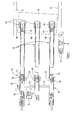
- FIG. 1 illustrates, diagrammatically, part of a thrust reverser system for use with an aircraft.
- the thrust reverser system comprises a cowl 10 guided for movement relative to an aircraft engine by a pair of guide tracks 12.
- the cowl 10 is arranged to be driven for movement along the guide tracks 12 by a drive arrangement 14 which comprises three linear actuators 16 arranged to be driven by a single, common electric motor 18.
- Each actuator 16 is in the form of a screw-jack actuator.
- a first one of the actuators 16, actuator 16a is located adjacent one of the tracks 12, a second one of the actuators 16, actuator 16b, being located adjacent the other of the tracks 12. Intermediate the first and second actuators 16a, 16b is located a third, intermediate actuator 16c.
- Each actuator 16 is secured by a respective mounting 20 to the cowl 10, and is also secured by gimbal mounting means 22 to a fixed part of the engine housing or wing structure (not shown).
- the electric motor 18 is arranged to drive the third actuator 16c directly, and flexible drive transmission shafts 24 are arranged to transmit drive from the third actuator 16c to the first and second actuators 16a, 16b.
- the first and second actuators 16a, 16b are substantially identical to one another and incorporate stops 26 operable to limit extending and retracting movement of the actuators 16a and 16b, lock arrangements 28 operable to lock these actuators against movement, and sensors 30 operable to output signals indicative of the operating status of the lock arrangements 28 to an associated control unit (not shown).
- the thrust reverser system further comprises a track lock or tertiary lock 32 operable to lock the cowl 10 against movement relative to one of the tracks 12, the track lock 32 having sensors 34 associated therewith to output signals representative of the status of the track lock 32 to the control unit.
- a position sensor in the form of an RVDT or an LVDT 36 monitors the operation of one of the actuators 16 to provide a signal indicative of the position of the actuators 16 and hence the cowl 10 for use by the control unit.
- the third actuator 16c is of a different design to the first and second actuators 16a, 16b. This arises from the fact that the loadings experienced by the third actuator 16c are considerably smaller than those experienced by the first and second actuators 16, 16b, in normal use. As a consequence, the third actuator 16c can be of reduced size and weight compared to the first and second actuators 16a, 16b, thereby achieving a weight saving. There is also no need to provide the third actuator 16c with the stops 26, lock 28 or associated sensors 30, thereby achieving further weight and cost savings. As mentioned hereinbefore, the third, smaller and/or lighter actuator 16c is capable of withstanding smaller loadings than can be withstood by the first and second actuators 16a, 16b.
- the track lock 32 and locks 28 are instructed to release, and the outputs of the sensors 30, 34 are used by the control unit to determine that the system is unlocked.
- the motor 18 is then operated to drive the actuators 16, and hence the cowl 10, for movement.
- the motor 18 is driven to cause an extension of all three of the actuators 16, thereby driving the cowl 10 for movement.
- the actuators 16 are under compression, the actuators 16 having to positively drive the cowl 10 for movement.
- the aerodynamic loads on the cowl 10 will tend to drag the cowl 10 towards its deployed position, placing the actuators 16 under tension.
- the first and second actuators 16a, 16b are each provided with a no-back device 38 operable to apply a braking load when the actuators 16a, 16b are under tension, the braking load being operable to resist such movement of the cowl 10 and thereby ensure that further movement of the cowl 10 occurs in a controlled manner.
- a load limiter device 40 is incorporated into the third actuator 16c.
- the load limiter device 40 is arranged such that if the third actuator 16c experiences a compressive load higher than a predetermined level (set at a level higher than would be expected during normal operation), the load limiter device 40 applies a braking load to part of the actuator to prevent continued operation of the motor from continuing to increase the compression of the third actuator 16c.
- the third actuator 16c is provided with the load limiter device 40 whereby, once the output compressive force exceeds a predetermined level, at least part of the output torque applied to the actuator is reacted to the housing of the actuator 16c.
- the overall load transmitted through the actuator 16c to the cowl 10 is thus reduced, avoiding the situation where the full output loading of the motor has to be accommodated by the entire actuator and so the risk of permanent damage of parts thereof is reduced.
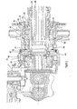
- the third actuator 16c is conveniently of the form illustrated in Figure 2 .
- the actuator shown in Figure 2 comprises a rotatable actuator member 42 supported for rotation within a housing 44.
- the actuator member 42 includes a region 46 of tubular form having, at an end thereof, a threaded nut (not shown) secured through a ball or roller-screw coupling to a threaded output shaft 48.
- the output shaft 48 is secured to the associated mounting 20 in such a manner that the output shaft 48 is unable to rotate. It will be appreciated that, in use, rotation of the actuator member 42 under the control of the electric motor 18 results in axial displacement of the output shaft 48 relative to the housing 44, and thus results in displacement of the cowl 10, in use.
- the load limiter device 40 is interposed between the tubular part 46 of the rotary actuator member 42 and the housing 44.
- the load limiter device 40 comprises a first stop member 50 which is secured to the rotary actuator member 42 so as to be rotatable therewith and to be axially fixed relative to the rotary actuator member 42, in use, by being abutted against a shoulder formed thereon.
- a key, spline or other connection arrangement may be used to ensure that rotary movement of the first stop member 50 relative to the rotary actuator member 42 is not permitted.
- the first stop member 50 includes a radially outwardly extending flange 52 which, in the position illustrated in Figure 2 , is spaced by a small distance from an abutment surface 54 of an abutment member 56 rigidly secured to the housing 44.
- a second stop member 58 is also secured to the rotary actuator member 42 in such a manner that rotary movement thereof relative to the actuator member 42 is not permitted. This is conveniently achieved by a spline, key or other similar coupling.
- the second stop member 58 includes a radially outwardly extending flange 60 which in the position illustrated in Figure 2 is spaced by a small distance from a second abutment surface 62 of an abutment member 64 also rigidly secured to the housing 44.
- the first stop member 50 includes a series of fingers 64 which are interleaved with similar fingers 66 provided on the second stop member 58.
- Bearing means 68 encircle the fingers 64, 66, the bearing means 68 comprising inner races 70 supported on the fingers 64, 66 for rotation therewith, outer races 72 secured to the fixed abutment member 56, and ball bearings 74 located therebetween.
- the fingers 64, 66 are provided, at their free ends, with outwardly extending lips 64a, 66a which are engageable with the inner races 70 to hold the first and second stop members 50, 58 captive to the bearing means 68.
- Resilient biasing means in the form of first and second disc spring packs 76, 78 are located between the flanges 52, 60 of the first and second stop members 52, 58 respectively, and the bearing means 68.
- the biasing means urges the second stop member 58 against a stop 80 secured to the actuator member 46, and the first stop member 50 against the associated shoulder on the actuator member 46.
- the biasing means serves to hold the rotary actuator member 46 in a substantially fixed axial position relative to the housing 44, the bearing means 68 supporting the actuator member 46 for rotation.
- FIG. 6 illustrates the case where a large magnitude compressive load is experienced, as would occur in the failure mode outlined hereinbefore due to the very high torque being applied to the actuator. In such a situation, the compressive load is sufficient to move the actuator member 46 to the left, in the orientation illustrated, against the net biasing load applied by the biasing means to a position in which the flange 52 of the first stop member 50 abuts the first abutment surface 54 of the abutment member 56 which is secured to the housing.
- Figure 7 illustrates the case where a large tensile load is applied, illustrating a load path 88 which serves, in addition to load path 84, to react tensile loadings, and additionally to react torque loadings to the housing 44.
- the load limiter device 40 operates as a brake, resisting rotation of the actuator member 46 when the tensile load or compressive load exceeds a predetermined level.
- the application of excessive compressive loads via the output shaft 48 as would otherwise occur in the failure mode outlined hereinbefore is avoided and so the risk of permanent damage to the actuator is reduced. It will be appreciated that this manner of operation is quite different to the operation of a torque limiter which releases upon the application of an excessive torque thereto.
- load limiter device 40 illustrated in Figures 2 to 7 is advantageous in that, as the first and second stop members are held captive to the bearing means, the load limiter device 40 can be pre-assembled and tested as a module prior to mounting on the actuator.
- the invention is not restricted to the use of this specific type of load limiter device.
Landscapes
- Engineering & Computer Science (AREA)
- Chemical & Material Sciences (AREA)
- Combustion & Propulsion (AREA)
- Mechanical Engineering (AREA)
- General Engineering & Computer Science (AREA)
- Aviation & Aerospace Engineering (AREA)
- Transmission Devices (AREA)
Applications Claiming Priority (1)
| Application Number | Priority Date | Filing Date | Title |
|---|---|---|---|
| GBGB0917065.5A GB0917065D0 (en) | 2009-09-29 | 2009-09-29 | Thrust reverser actuation |
Publications (3)
| Publication Number | Publication Date |
|---|---|
| EP2301845A2 true EP2301845A2 (fr) | 2011-03-30 |
| EP2301845A3 EP2301845A3 (fr) | 2012-11-28 |
| EP2301845B1 EP2301845B1 (fr) | 2014-07-30 |
Family
ID=41350540
Family Applications (1)
| Application Number | Title | Priority Date | Filing Date |
|---|---|---|---|
| EP10251659.8A Active EP2301845B1 (fr) | 2009-09-29 | 2010-09-27 | Actionnement d'inverseur de poussée |
Country Status (3)
| Country | Link |
|---|---|
| US (1) | US8632033B2 (fr) |
| EP (1) | EP2301845B1 (fr) |
| GB (1) | GB0917065D0 (fr) |
Families Citing this family (7)
| Publication number | Priority date | Publication date | Assignee | Title |
|---|---|---|---|---|
| US8281678B2 (en) | 2008-12-30 | 2012-10-09 | Eaton Corporation | Ballscrew assembly with detection feature |
| GB0917057D0 (en) | 2009-09-29 | 2009-11-11 | Goodrich Actuation Systems Ltd | Thrust reverser actuation |
| US9086035B2 (en) * | 2012-01-20 | 2015-07-21 | Hamilton Sundstrand Corporation | Integrated thrust reverser actuator and variable area fan nozzle actuator |
| US9188081B2 (en) | 2012-04-10 | 2015-11-17 | Honeywell International Inc. | Thrust reverser actuator with primary lock |
| US9650993B2 (en) | 2013-10-23 | 2017-05-16 | Honeywell International Inc. | Rotary hydraulic motor driven hybrid thrust reverser actuation system with end-of-stroke snubbing |
| US10161356B2 (en) | 2014-06-02 | 2018-12-25 | Ge Aviation Systems Llc | Integrated thrust reverser actuation system |
| FR3100577B1 (fr) * | 2019-09-05 | 2021-12-03 | Safran Nacelles | Inverseur de poussée comprenant un unique vérin de commande de capot mobile |
Citations (3)
| Publication number | Priority date | Publication date | Assignee | Title |
|---|---|---|---|---|
| WO2004113707A1 (fr) | 2003-06-18 | 2004-12-29 | Honeywell International Inc. | Actionneur pour systeme d'inversion de la poussee a limiteur de couple integre |
| GB2408725A (en) | 2003-12-02 | 2005-06-08 | Goodrich Actuation Systems Ltd | Thrust reverser actuation system |
| EP1972548A2 (fr) | 2007-03-20 | 2008-09-24 | Goodrich Actuation Systems Ltd. | Agencement d'actionneur |
Family Cites Families (9)
| Publication number | Priority date | Publication date | Assignee | Title |
|---|---|---|---|---|
| US3596740A (en) * | 1970-01-27 | 1971-08-03 | Trw Inc | Torque limiter |
| US4898265A (en) * | 1988-01-27 | 1990-02-06 | Sundstrand Corporation | Torque limiter |
| US6202803B1 (en) * | 1998-12-22 | 2001-03-20 | Hamilton Sundstrand Corporation | Output load limiter |
| US6526744B2 (en) * | 2001-04-30 | 2003-03-04 | Honeywell International Inc. | System and method for controlling the stowage of jet engine thrust reversers |
| GB0116674D0 (en) * | 2001-07-07 | 2001-08-29 | Lucas Industries Ltd | Screw actuator |
| US6598386B2 (en) * | 2001-10-16 | 2003-07-29 | Honeywell International, Inc. | Jet engine thrust reverser system having torque limited synchronization |
| FR2846377B1 (fr) * | 2002-10-25 | 2006-06-30 | Hispano Suiza Sa | Inverseur de poussee electromecanique pour turboreacteur a controle permanent de position |
| GB0421568D0 (en) * | 2004-09-29 | 2004-10-27 | Smiths Group Plc | Drive assemblies |
| GB0706524D0 (en) * | 2007-04-04 | 2007-05-09 | Goodrich Actuation Systems Ltd | Actuator arrangement |
-
2009
- 2009-09-29 GB GBGB0917065.5A patent/GB0917065D0/en not_active Ceased
-
2010
- 2010-09-27 EP EP10251659.8A patent/EP2301845B1/fr active Active
- 2010-09-29 US US12/893,494 patent/US8632033B2/en active Active
Patent Citations (3)
| Publication number | Priority date | Publication date | Assignee | Title |
|---|---|---|---|---|
| WO2004113707A1 (fr) | 2003-06-18 | 2004-12-29 | Honeywell International Inc. | Actionneur pour systeme d'inversion de la poussee a limiteur de couple integre |
| GB2408725A (en) | 2003-12-02 | 2005-06-08 | Goodrich Actuation Systems Ltd | Thrust reverser actuation system |
| EP1972548A2 (fr) | 2007-03-20 | 2008-09-24 | Goodrich Actuation Systems Ltd. | Agencement d'actionneur |
Also Published As
| Publication number | Publication date |
|---|---|
| EP2301845B1 (fr) | 2014-07-30 |
| GB0917065D0 (en) | 2009-11-11 |
| US20110232406A1 (en) | 2011-09-29 |
| EP2301845A3 (fr) | 2012-11-28 |
| US8632033B2 (en) | 2014-01-21 |
Similar Documents
| Publication | Publication Date | Title |
|---|---|---|
| EP2311731B1 (fr) | Actionnement d'inverseur de poussée | |
| EP2301845B1 (fr) | Actionnement d'inverseur de poussée | |
| US8393568B2 (en) | Enhanced lubrication skewed roller clutch assembly and actuator including same | |
| EP1972548B1 (fr) | Agencement d'actionneur | |
| US7919938B2 (en) | Actuator arrangement | |
| US7690597B2 (en) | Flap actuator | |
| US6494033B1 (en) | Sequentially operated actuator with brake arrangement | |
| EP2306041B1 (fr) | Dispositif anti-retour | |
| EP3992496B1 (fr) | Actionneur électromécanique avec système de anti-retour | |
| EP3613667B1 (fr) | Actionneur linéaire à cône anti-retour et limiteur de couple testables | |
| EP2280194A1 (fr) | Actionneur rotatif | |
| EP1980770B1 (fr) | Agencement d'actionneur | |
| EP3404245B1 (fr) | Système de verrouillage tertiaire pour un inverseur de poussée | |
| EP3296586A1 (fr) | Agencement sans arrière d'actionneur |
Legal Events
| Date | Code | Title | Description |
|---|---|---|---|
| PUAI | Public reference made under article 153(3) epc to a published international application that has entered the european phase |
Free format text: ORIGINAL CODE: 0009012 |
|
| AK | Designated contracting states |
Kind code of ref document: A2 Designated state(s): AL AT BE BG CH CY CZ DE DK EE ES FI FR GB GR HR HU IE IS IT LI LT LU LV MC MK MT NL NO PL PT RO SE SI SK SM TR |
|
| AX | Request for extension of the european patent |
Extension state: BA ME RS |
|
| PUAL | Search report despatched |
Free format text: ORIGINAL CODE: 0009013 |
|
| AK | Designated contracting states |
Kind code of ref document: A3 Designated state(s): AL AT BE BG CH CY CZ DE DK EE ES FI FR GB GR HR HU IE IS IT LI LT LU LV MC MK MT NL NO PL PT RO SE SI SK SM TR |
|
| AX | Request for extension of the european patent |
Extension state: BA ME RS |
|
| RIC1 | Information provided on ipc code assigned before grant |
Ipc: F02K 1/76 20060101ALI20121019BHEP Ipc: B64D 33/04 20060101AFI20121019BHEP |
|
| 17P | Request for examination filed |
Effective date: 20130528 |
|
| RBV | Designated contracting states (corrected) |
Designated state(s): AL AT BE BG CH CY CZ DE DK EE ES FI FR GB GR HR HU IE IS IT LI LT LU LV MC MK MT NL NO PL PT RO SE SI SK SM TR |
|
| GRAP | Despatch of communication of intention to grant a patent |
Free format text: ORIGINAL CODE: EPIDOSNIGR1 |
|
| INTG | Intention to grant announced |
Effective date: 20140207 |
|
| GRAS | Grant fee paid |
Free format text: ORIGINAL CODE: EPIDOSNIGR3 |
|
| GRAA | (expected) grant |
Free format text: ORIGINAL CODE: 0009210 |
|
| AK | Designated contracting states |
Kind code of ref document: B1 Designated state(s): AL AT BE BG CH CY CZ DE DK EE ES FI FR GB GR HR HU IE IS IT LI LT LU LV MC MK MT NL NO PL PT RO SE SI SK SM TR |
|
| REG | Reference to a national code |
Ref country code: GB Ref legal event code: FG4D |
|
| REG | Reference to a national code |
Ref country code: CH Ref legal event code: EP |
|
| REG | Reference to a national code |
Ref country code: AT Ref legal event code: REF Ref document number: 679824 Country of ref document: AT Kind code of ref document: T Effective date: 20140815 |
|
| REG | Reference to a national code |
Ref country code: IE Ref legal event code: FG4D |
|
| REG | Reference to a national code |
Ref country code: DE Ref legal event code: R096 Ref document number: 602010017867 Country of ref document: DE Effective date: 20140911 |
|
| REG | Reference to a national code |
Ref country code: AT Ref legal event code: MK05 Ref document number: 679824 Country of ref document: AT Kind code of ref document: T Effective date: 20140730 |
|
| REG | Reference to a national code |
Ref country code: NL Ref legal event code: VDEP Effective date: 20140730 |
|
| REG | Reference to a national code |
Ref country code: LT Ref legal event code: MG4D |
|
| PG25 | Lapsed in a contracting state [announced via postgrant information from national office to epo] |
Ref country code: BG Free format text: LAPSE BECAUSE OF FAILURE TO SUBMIT A TRANSLATION OF THE DESCRIPTION OR TO PAY THE FEE WITHIN THE PRESCRIBED TIME-LIMIT Effective date: 20141030 Ref country code: PT Free format text: LAPSE BECAUSE OF FAILURE TO SUBMIT A TRANSLATION OF THE DESCRIPTION OR TO PAY THE FEE WITHIN THE PRESCRIBED TIME-LIMIT Effective date: 20141202 Ref country code: SE Free format text: LAPSE BECAUSE OF FAILURE TO SUBMIT A TRANSLATION OF THE DESCRIPTION OR TO PAY THE FEE WITHIN THE PRESCRIBED TIME-LIMIT Effective date: 20140730 Ref country code: LT Free format text: LAPSE BECAUSE OF FAILURE TO SUBMIT A TRANSLATION OF THE DESCRIPTION OR TO PAY THE FEE WITHIN THE PRESCRIBED TIME-LIMIT Effective date: 20140730 Ref country code: FI Free format text: LAPSE BECAUSE OF FAILURE TO SUBMIT A TRANSLATION OF THE DESCRIPTION OR TO PAY THE FEE WITHIN THE PRESCRIBED TIME-LIMIT Effective date: 20140730 Ref country code: GR Free format text: LAPSE BECAUSE OF FAILURE TO SUBMIT A TRANSLATION OF THE DESCRIPTION OR TO PAY THE FEE WITHIN THE PRESCRIBED TIME-LIMIT Effective date: 20141031 Ref country code: ES Free format text: LAPSE BECAUSE OF FAILURE TO SUBMIT A TRANSLATION OF THE DESCRIPTION OR TO PAY THE FEE WITHIN THE PRESCRIBED TIME-LIMIT Effective date: 20140730 Ref country code: NO Free format text: LAPSE BECAUSE OF FAILURE TO SUBMIT A TRANSLATION OF THE DESCRIPTION OR TO PAY THE FEE WITHIN THE PRESCRIBED TIME-LIMIT Effective date: 20141030 |
|
| PG25 | Lapsed in a contracting state [announced via postgrant information from national office to epo] |
Ref country code: LV Free format text: LAPSE BECAUSE OF FAILURE TO SUBMIT A TRANSLATION OF THE DESCRIPTION OR TO PAY THE FEE WITHIN THE PRESCRIBED TIME-LIMIT Effective date: 20140730 Ref country code: AT Free format text: LAPSE BECAUSE OF FAILURE TO SUBMIT A TRANSLATION OF THE DESCRIPTION OR TO PAY THE FEE WITHIN THE PRESCRIBED TIME-LIMIT Effective date: 20140730 Ref country code: CY Free format text: LAPSE BECAUSE OF FAILURE TO SUBMIT A TRANSLATION OF THE DESCRIPTION OR TO PAY THE FEE WITHIN THE PRESCRIBED TIME-LIMIT Effective date: 20140730 Ref country code: HR Free format text: LAPSE BECAUSE OF FAILURE TO SUBMIT A TRANSLATION OF THE DESCRIPTION OR TO PAY THE FEE WITHIN THE PRESCRIBED TIME-LIMIT Effective date: 20140730 Ref country code: PL Free format text: LAPSE BECAUSE OF FAILURE TO SUBMIT A TRANSLATION OF THE DESCRIPTION OR TO PAY THE FEE WITHIN THE PRESCRIBED TIME-LIMIT Effective date: 20140730 Ref country code: IS Free format text: LAPSE BECAUSE OF FAILURE TO SUBMIT A TRANSLATION OF THE DESCRIPTION OR TO PAY THE FEE WITHIN THE PRESCRIBED TIME-LIMIT Effective date: 20141130 Ref country code: NL Free format text: LAPSE BECAUSE OF FAILURE TO SUBMIT A TRANSLATION OF THE DESCRIPTION OR TO PAY THE FEE WITHIN THE PRESCRIBED TIME-LIMIT Effective date: 20140730 |
|
| PG25 | Lapsed in a contracting state [announced via postgrant information from national office to epo] |
Ref country code: IT Free format text: LAPSE BECAUSE OF FAILURE TO SUBMIT A TRANSLATION OF THE DESCRIPTION OR TO PAY THE FEE WITHIN THE PRESCRIBED TIME-LIMIT Effective date: 20140730 Ref country code: EE Free format text: LAPSE BECAUSE OF FAILURE TO SUBMIT A TRANSLATION OF THE DESCRIPTION OR TO PAY THE FEE WITHIN THE PRESCRIBED TIME-LIMIT Effective date: 20140730 Ref country code: LU Free format text: LAPSE BECAUSE OF FAILURE TO SUBMIT A TRANSLATION OF THE DESCRIPTION OR TO PAY THE FEE WITHIN THE PRESCRIBED TIME-LIMIT Effective date: 20140927 Ref country code: SK Free format text: LAPSE BECAUSE OF FAILURE TO SUBMIT A TRANSLATION OF THE DESCRIPTION OR TO PAY THE FEE WITHIN THE PRESCRIBED TIME-LIMIT Effective date: 20140730 Ref country code: CZ Free format text: LAPSE BECAUSE OF FAILURE TO SUBMIT A TRANSLATION OF THE DESCRIPTION OR TO PAY THE FEE WITHIN THE PRESCRIBED TIME-LIMIT Effective date: 20140730 Ref country code: MC Free format text: LAPSE BECAUSE OF FAILURE TO SUBMIT A TRANSLATION OF THE DESCRIPTION OR TO PAY THE FEE WITHIN THE PRESCRIBED TIME-LIMIT Effective date: 20140730 Ref country code: RO Free format text: LAPSE BECAUSE OF FAILURE TO SUBMIT A TRANSLATION OF THE DESCRIPTION OR TO PAY THE FEE WITHIN THE PRESCRIBED TIME-LIMIT Effective date: 20140730 Ref country code: DK Free format text: LAPSE BECAUSE OF FAILURE TO SUBMIT A TRANSLATION OF THE DESCRIPTION OR TO PAY THE FEE WITHIN THE PRESCRIBED TIME-LIMIT Effective date: 20140730 |
|
| REG | Reference to a national code |
Ref country code: CH Ref legal event code: PL |
|
| REG | Reference to a national code |
Ref country code: DE Ref legal event code: R097 Ref document number: 602010017867 Country of ref document: DE |
|
| PLBE | No opposition filed within time limit |
Free format text: ORIGINAL CODE: 0009261 |
|
| STAA | Information on the status of an ep patent application or granted ep patent |
Free format text: STATUS: NO OPPOSITION FILED WITHIN TIME LIMIT |
|
| REG | Reference to a national code |
Ref country code: IE Ref legal event code: MM4A |
|
| PG25 | Lapsed in a contracting state [announced via postgrant information from national office to epo] |
Ref country code: BE Free format text: LAPSE BECAUSE OF NON-PAYMENT OF DUE FEES Effective date: 20140930 |
|
| 26N | No opposition filed |
Effective date: 20150504 |
|
| PG25 | Lapsed in a contracting state [announced via postgrant information from national office to epo] |
Ref country code: CH Free format text: LAPSE BECAUSE OF NON-PAYMENT OF DUE FEES Effective date: 20140930 Ref country code: LI Free format text: LAPSE BECAUSE OF NON-PAYMENT OF DUE FEES Effective date: 20140930 |
|
| REG | Reference to a national code |
Ref country code: FR Ref legal event code: PLFP Year of fee payment: 6 |
|
| PG25 | Lapsed in a contracting state [announced via postgrant information from national office to epo] |
Ref country code: IE Free format text: LAPSE BECAUSE OF NON-PAYMENT OF DUE FEES Effective date: 20140927 |
|
| PG25 | Lapsed in a contracting state [announced via postgrant information from national office to epo] |
Ref country code: SI Free format text: LAPSE BECAUSE OF FAILURE TO SUBMIT A TRANSLATION OF THE DESCRIPTION OR TO PAY THE FEE WITHIN THE PRESCRIBED TIME-LIMIT Effective date: 20140730 |
|
| PG25 | Lapsed in a contracting state [announced via postgrant information from national office to epo] |
Ref country code: SM Free format text: LAPSE BECAUSE OF FAILURE TO SUBMIT A TRANSLATION OF THE DESCRIPTION OR TO PAY THE FEE WITHIN THE PRESCRIBED TIME-LIMIT Effective date: 20140730 |
|
| PG25 | Lapsed in a contracting state [announced via postgrant information from national office to epo] |
Ref country code: MT Free format text: LAPSE BECAUSE OF FAILURE TO SUBMIT A TRANSLATION OF THE DESCRIPTION OR TO PAY THE FEE WITHIN THE PRESCRIBED TIME-LIMIT Effective date: 20140730 |
|
| PG25 | Lapsed in a contracting state [announced via postgrant information from national office to epo] |
Ref country code: TR Free format text: LAPSE BECAUSE OF FAILURE TO SUBMIT A TRANSLATION OF THE DESCRIPTION OR TO PAY THE FEE WITHIN THE PRESCRIBED TIME-LIMIT Effective date: 20140730 Ref country code: BE Free format text: LAPSE BECAUSE OF FAILURE TO SUBMIT A TRANSLATION OF THE DESCRIPTION OR TO PAY THE FEE WITHIN THE PRESCRIBED TIME-LIMIT Effective date: 20140730 Ref country code: HU Free format text: LAPSE BECAUSE OF FAILURE TO SUBMIT A TRANSLATION OF THE DESCRIPTION OR TO PAY THE FEE WITHIN THE PRESCRIBED TIME-LIMIT; INVALID AB INITIO Effective date: 20100927 |
|
| REG | Reference to a national code |
Ref country code: FR Ref legal event code: PLFP Year of fee payment: 7 |
|
| REG | Reference to a national code |
Ref country code: DE Ref legal event code: R082 Ref document number: 602010017867 Country of ref document: DE Representative=s name: SCHMITT-NILSON SCHRAUD WAIBEL WOHLFROM PATENTA, DE |
|
| REG | Reference to a national code |
Ref country code: FR Ref legal event code: PLFP Year of fee payment: 8 |
|
| PG25 | Lapsed in a contracting state [announced via postgrant information from national office to epo] |
Ref country code: MK Free format text: LAPSE BECAUSE OF FAILURE TO SUBMIT A TRANSLATION OF THE DESCRIPTION OR TO PAY THE FEE WITHIN THE PRESCRIBED TIME-LIMIT Effective date: 20140730 |
|
| REG | Reference to a national code |
Ref country code: FR Ref legal event code: PLFP Year of fee payment: 9 |
|
| PG25 | Lapsed in a contracting state [announced via postgrant information from national office to epo] |
Ref country code: AL Free format text: LAPSE BECAUSE OF FAILURE TO SUBMIT A TRANSLATION OF THE DESCRIPTION OR TO PAY THE FEE WITHIN THE PRESCRIBED TIME-LIMIT Effective date: 20140730 |
|
| PGFP | Annual fee paid to national office [announced via postgrant information from national office to epo] |
Ref country code: DE Payment date: 20250820 Year of fee payment: 16 |
|
| PGFP | Annual fee paid to national office [announced via postgrant information from national office to epo] |
Ref country code: GB Payment date: 20250822 Year of fee payment: 16 |
|
| PGFP | Annual fee paid to national office [announced via postgrant information from national office to epo] |
Ref country code: FR Payment date: 20250820 Year of fee payment: 16 |