EP2301867A2 - Dispositif de transfert de récipients entre deux stations de traitement et procédé de transfert de récipients entre deux stations de traitement - Google Patents
Dispositif de transfert de récipients entre deux stations de traitement et procédé de transfert de récipients entre deux stations de traitement Download PDFInfo
- Publication number
- EP2301867A2 EP2301867A2 EP10174380A EP10174380A EP2301867A2 EP 2301867 A2 EP2301867 A2 EP 2301867A2 EP 10174380 A EP10174380 A EP 10174380A EP 10174380 A EP10174380 A EP 10174380A EP 2301867 A2 EP2301867 A2 EP 2301867A2
- Authority
- EP
- European Patent Office
- Prior art keywords
- transport
- processing station
- containers
- transfer
- unit
- Prior art date
- Legal status (The legal status is an assumption and is not a legal conclusion. Google has not performed a legal analysis and makes no representation as to the accuracy of the status listed.)
- Granted
Links
Images






Classifications
-
- B—PERFORMING OPERATIONS; TRANSPORTING
- B65—CONVEYING; PACKING; STORING; HANDLING THIN OR FILAMENTARY MATERIAL
- B65G—TRANSPORT OR STORAGE DEVICES, e.g. CONVEYORS FOR LOADING OR TIPPING, SHOP CONVEYOR SYSTEMS OR PNEUMATIC TUBE CONVEYORS
- B65G47/00—Article or material-handling devices associated with conveyors; Methods employing such devices
- B65G47/34—Devices for discharging articles or materials from conveyor
- B65G47/46—Devices for discharging articles or materials from conveyor and distributing, e.g. automatically, to desired points
- B65G47/51—Devices for discharging articles or materials from conveyor and distributing, e.g. automatically, to desired points according to unprogrammed signals, e.g. influenced by supply situation at destination
- B65G47/5104—Devices for discharging articles or materials from conveyor and distributing, e.g. automatically, to desired points according to unprogrammed signals, e.g. influenced by supply situation at destination for articles
- B65G47/5109—Devices for discharging articles or materials from conveyor and distributing, e.g. automatically, to desired points according to unprogrammed signals, e.g. influenced by supply situation at destination for articles first In - First Out systems: FIFO
- B65G47/5113—Devices for discharging articles or materials from conveyor and distributing, e.g. automatically, to desired points according to unprogrammed signals, e.g. influenced by supply situation at destination for articles first In - First Out systems: FIFO using endless conveyors
-
- B—PERFORMING OPERATIONS; TRANSPORTING
- B65—CONVEYING; PACKING; STORING; HANDLING THIN OR FILAMENTARY MATERIAL
- B65G—TRANSPORT OR STORAGE DEVICES, e.g. CONVEYORS FOR LOADING OR TIPPING, SHOP CONVEYOR SYSTEMS OR PNEUMATIC TUBE CONVEYORS
- B65G35/00—Mechanical conveyors not otherwise provided for
- B65G35/08—Mechanical conveyors not otherwise provided for comprising trains of unconnected load-carriers, e.g. belt sections, movable in a path, e.g. a closed path, adapted to contact each other and to be propelled by means arranged to engage each load-carrier in turn
-
- B—PERFORMING OPERATIONS; TRANSPORTING
- B65—CONVEYING; PACKING; STORING; HANDLING THIN OR FILAMENTARY MATERIAL
- B65G—TRANSPORT OR STORAGE DEVICES, e.g. CONVEYORS FOR LOADING OR TIPPING, SHOP CONVEYOR SYSTEMS OR PNEUMATIC TUBE CONVEYORS
- B65G19/00—Conveyors comprising an impeller or a series of impellers carried by an endless traction element and arranged to move articles or materials over a supporting surface or underlying material, e.g. endless scraper conveyors
- B65G19/02—Conveyors comprising an impeller or a series of impellers carried by an endless traction element and arranged to move articles or materials over a supporting surface or underlying material, e.g. endless scraper conveyors for articles, e.g. for containers
- B65G19/025—Conveyors comprising an impeller or a series of impellers carried by an endless traction element and arranged to move articles or materials over a supporting surface or underlying material, e.g. endless scraper conveyors for articles, e.g. for containers for suspended articles
-
- B—PERFORMING OPERATIONS; TRANSPORTING
- B65—CONVEYING; PACKING; STORING; HANDLING THIN OR FILAMENTARY MATERIAL
- B65G—TRANSPORT OR STORAGE DEVICES, e.g. CONVEYORS FOR LOADING OR TIPPING, SHOP CONVEYOR SYSTEMS OR PNEUMATIC TUBE CONVEYORS
- B65G2201/00—Indexing codes relating to handling devices, e.g. conveyors, characterised by the type of product or load being conveyed or handled
- B65G2201/02—Articles
- B65G2201/0235—Containers
- B65G2201/0244—Bottles
- B65G2201/0247—Suspended bottles
Definitions
- the present invention relates to a device for transferring containers between two processing stations, a transport unit used therefor and a corresponding method having the features of the preambles of claims 1, 6 and 8.
- the invention is intended for the transfer of hollow bodies, in particular plastic containers, between two processing stations of a beverage filling device, for example between a blow molding machine and a labeling machine.
- Out EP 1 107 588 B1 a device is known in which the plastic bottles continuously produced in a blow molding machine are fed via an outlet star in the outlet of the blow molding machine of a labeling machine, so that the bottles are labeled immediately after leaving the blow molding machine in a continuous stream.
- the outlet star of the blow molding machine is also used as an infeed star for the labeling machine.
- US 5996322 describes a bottle filling station, which consists of a device for producing containers, preferably a blow molding machine, and a filling device.
- the two devices are arranged as close as possible, with the shortest possible delivery unit between them.
- an additional unit may be provided to temporarily hold the bottles.
- DE 10 2006 013 800 B3 also describes a transport system for the transport of bottles or the like between a first and a second machine, for example between a blowing machine and a filling station with a transfer element in the form of a transfer star with a plurality of container receptacles.
- DE 199 28 325 A1 discloses a bottling device for bottles in which a bottle blowing machine, a dishwasher and a filling machine are connected in series, wherein the bottles are transferred by interlocking transport elements between the machines.
- the transport elements are so-called infeed or outfeed stars with grippers.
- the object of the invention is to close the possibly arising at the outlet from a first processing station gaps to allow continuous processing by a downstream second processing station.
- the above object is achieved by a device comprising the features of claim 1.
- the object is further achieved by a method for seamless transfer according to the features of claim 8.
- the present invention is preferably used in a beverage bottling plant.
- a beverage bottling plant consists for example of a blow molding machine, a labeling device, a filling device and a closure device.
- the invention relates to a device for transferring containers from a first processing station to a second processing station.
- the device comprises at least one, preferably two transfer units and a buffer with individually controllable transport units for the containers and a control unit.
- the transport units are controlled in such a way that the buffer interacts with the second processing station, so that a transfer of the containers from the buffer to the second processing station takes place synchronously.
- the first transfer unit at which the containers arriving from the first processing station are transferred to the container transfer system, is assigned a controllable blocking device.
- empty transport units are accumulated in front of the first transfer unit and released in a controlled manner by means of the above-mentioned blocking device for receiving a container brought from a first processing station.
- An opening of the locking device and thus a release of a transport unit takes place only if previously the arrival of a container was detected from the first processing station.
- a detection device for example, a light barrier or similar use.
- the locking device remains closed, so that no release of a transport unit takes place when a gap in the incoming container stream is detected.
- the first processing station is a blow molding machine.
- the containers produced by the blow molding machine are checked, for example, by means of image-recognizing algorithms and faulty containers are automatically detected and rejected.
- gaps in the container flow which is supplied to the second processing station, arise. If these gaps are not compensated, then the second processing station either has to be stopped for a short time, or the processing steps go nowhere because there is no object to be processed.
- the second processing station is a labeling device.
- the hollow body produced by the blow molding machine are preferably first labeled and then filled. This prevents liquid from condensing on the hollow bodies, which makes attachment of the labels very difficult.
- the buffer for the containers of the second transfer unit is assigned, in which the transfer of the containers to the second processing unit, in particular the labeler takes place.
- the transport units are guided in an example designed as an endless loop transport path, which has in each case a deflection at the first and at a second transfer unit.
- at least one drive device is provided in each case, which decelerates and / or accelerates the transport units.
- the transport path consists for example of two parallel metal tubes or C-profiles or a comparable guide system.
- empty trolleys are braked and accumulated on a drive unit upstream of the first transfer unit. Subsequently, at the first transfer unit, a controlled loading of individual transport vehicles, each with a container. The loaded transport unit is then accelerated by one of the first transfer unit downstream drive device in the direction of the second transfer unit and braked in turn by another drive device, so that before the second transfer unit loaded with containers transport units are accumulated, which form the buffer.
- the container stream supplied to the second processing station is generated by transferring the containers from the transport units to, for example, an infeed star of the second processing station at the second transfer unit.
- the drive devices are rotating brush drives.
- the transport units on the side facing the drive devices also brushes, which cooperate with the rotary brush drives in the manner of a hook and loop fastener.
- the belt engages in the transport unit and this accelerates or decelerates.
- magnets can repel or attract the transport trolleys from the infeed star or outlet star. It is necessary that ferromagnetic parts or permanent magnets are arranged on the trolleys, which are in interaction with fixed or attached to the endless belt of the transport path magnets.
- transfer units preferably sawtooth stars are used, which cause a simple further transport of the transport units.
- the containers are transported by an outlet star from the first processing station and transferred to the first transfer unit in the form of a sawtooth star.
- the transport units used are simple in construction and preferably have a passive gripper system for gripping, holding and transporting containers.
- the passive gripping system is preferably formed as a clip and can be automatically adjusted by means of springs to the size of the container to be transported, in particular to the thickness of the bottle neck below the support ring.
- Each transport unit has a first guide element, for example in the form of at least one roller for guidance in the transport path.
- each transport unit has a second guide element, via which the transport unit is received at the transfer units and actively taken along or guided.
- the second guide element may also be at least one roller or the like.
- the transport units are guided loosely in a transport loop or transport path and are mobile at variable speeds. In particular, they are accelerated after receiving containers on the first transfer unit or the inlet star and then braked in turn before the second transfer unit or the outlet star.
- the gripping system of the trolley for the containers can be loaded from two sides. This allows the trolleys to be used in different systems.
- the trolleys are slightly wider than the transported containers to avoid collisions of the containers.
- the dolly on the sides of buffer elements to prevent or dampen collisions may be, for example, rubber buffer or the like.
- the container buffer or storage, the at least one transfer unit and the at least two transport units are part of a container transfer system, which additionally has at least two so-called drive devices for accelerating and / or decelerating the transport units and a blocking device for blocking empty transport units ,
- the transport units are guided in a guide system.
- the invention further relates to a method for transferring containers from a first processing station to a second processing station, in which controllable transport units loaded in containers stored in a buffer are moved individually.
- the buffer cooperates with the second processing station in such a way that the containers are transferred from the buffer to the second processing station in a time-synchronized manner.
- the handover at the second processing station is independent of whether the containers are time synchronized, i. in a continuous, uninterrupted container stream at the transfer unit from the first processing station.
- the method preferably uses a container transfer system described above comprising two transfer units, a transport loop, at least two transport units, at least one blocking device and at least two drive devices and runs, for example, in the following steps: First, the arrival of a container from a first processing station is detected. Subsequently, a locking device is released, so that a transport unit is released to a first transfer unit.
- the Transport unit receives at the first transfer unit a container from the first processing station.
- the loaded transport unit is then accelerated via a drive element in the direction of a second transfer unit and decelerated before the second transfer unit and accumulated.
- the containers thus stored are continuously clocked at the second transfer unit as needed fed into the second processing station.
- the empty transport unit is then accelerated in the direction of the first transfer unit and in turn braked and accumulated in front of it so that they are available again for reloading with a container supplied by the first processing station.
- the containers are transferred to the second transfer unit directly to an infeed star of the second processing station, in particular a labeler.
- the containers can also be handed over to at least one intermediate neck handling system. This is particularly necessary if an opposite direction of travel of the containers in the second processing station counter to the direction after the transfer of the containers is required.
- the invention described is preferably used for the transfer of plastic containers, in particular plastic bottles, in particular made of PET, which have a support ring on the bottleneck.
- the plastic bottles can be filled or empty here.
- the invention can also be used to transport preforms.
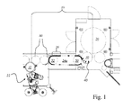
- FIG. 1 shows a schematic arrangement of arranged between a blow molding machine 20 and a labeling machine 22 means 10 for transfer of containers with a container transfer system with straight carriage guide 24a.
- the bottles 40 produced by the blow molding machine 20 are transferred via a discharge star 30 to a sawtooth star 50 of a container transfer system 24a and transported to the sawtooth star 52, where they are transferred to two neck handling systems 80 and then to the infeed star 32 of the labeling apparatus 22.
- the container transfer system 24a serves to close individual gaps that may arise in the delivery starter 30 after the blow molding machine 20 and thus to allow continuous operation of the labeling machine 22.
- the container transfer system 24a prevents the further processing steps, in particular the labeling, filling, etc., from being carried out with these defective bottles 40 and subsequently having to sort these defective containers.
- FIG. 2 shows a view of a container transfer system with straight carriage guide 24a between an outlet star 30 from a first device or processing station, in particular a blow molding machine 20 and an inlet star 32 or a neck handling system 80 in a second device or processing station, in particular in a labeling machine 22nd
- the container transfer system 24a consists of two sawtooth stars 50, 52, which are interconnected by a guide system 54.
- the guide system 54 consists of two parallel guide rails. These may preferably be metal tubes, C-profiles or the like.
- a container in particular a bottle 40
- the container transfer system by the discharge star 30 of the blow molding machine 20
- the container 40 is transferred by so-called neck handling.
- dolly 60 are arranged to receive the supplied bottles 40.
- the trolleys 60 are constructed so that their width corresponds to slightly more than the maximum width of the bottles 40 to be transported.
- brush drives 70, 72, 74 and 76 for driving and stopping the empty or loaded trolley 60 are arranged on the guide system 54.
- FIG. 3 illustrates in detail the situation between sawtooth star 50 and outlet star 30 of the blow molding machine 20.
- the bottles 40 are held, for example, in half-open active clamps 31.
- the opening widths of the gripper jaws 90 of the clamps 31 can be regulated in the illustrated embodiment by means of springs (not shown) corresponding to the width of the bottle neck.
- an empty transporting carriage 60 is provided for receiving a bottle 40 transported over the outlet starter 30 only when a bottle 40 has been detected in the corresponding bracket 31 of the outlet starter (not shown) via a detection system. Only then does the car lock 66 open and leaves a trolley 60 free.
- the carriage lock 66 closes so that no transport carriage 60 enters the sawtooth star 50. If a bottle 40 is subsequently located in the outlet star 30, the carriage lock 66 opens in time. Thus, it is ensured with the container transport system 24 a, that only with bottles 40 equipped transport vehicles 60 are transported from the outlet star 30 of the blow molding machine 20 to the inlet star 32 of the labeling machine 22.
- the sawtooth 50 transports the equipped with a bottle 40 trolley 60 via a guide system 54 to the Mink chain system (eg conveyor chains equipped with Mink V-belt brushes or the like) to a first rotating brush drive 70.
- the brush engages in the Dolly 60 and accelerates this in the direction of the second sawtooth star 52, which is located in the immediate vicinity of the inlet star 32 of the labeling machine 22 or a neck handling system 80 and causes the transfer of the bottles 40 to this.
- the sawtooth star 52 is driven in synchronism with the infeed star 32 of the labeling machine 22, whereby the car 60 are transported in line with the delivery point.
- the inlet star 32 of the labeling machine 22 has controlled brackets 33. These are closed at the transfer point between sawtooth star 52 and inlet star 32 and pull the bottles from the spring-loaded grippers 61 of the trolley 60th
- the now empty transport carriage 60 are transported by the sawtooth star 52 to a third brush conveyor 74 and passed through which the trolley 60 accelerated again and are driven in the direction of the first sawtooth star 50.
- a fourth brush drive 76 the empty trolleys 60 are ready for use in front of the car lock 66 on the first sawtooth star 50 accumulated before they are re-stocked with bottles 40.
- sufficiently jammed transport trolleys 60 with or without containers 40 must always be available in front of the transfer points on the sawtooth stars 50, 52.
- the transfer paths ie the guide system 54 between the transfer points on the sawtooth stars 50, 52, are not full with transport carriages 60, since then no acceleration of the transfer carriages 60 would be possible.
- the system described thus makes it possible to close a few gaps in the container flow arriving from the blow molding machine 20. If, due to other spatial and / or structural conditions, the running direction of the labeling machine 22 is opposite, it may be necessary to additionally interpose another neck handling system 80. Alternatively, a container transfer system with crossed carriage guide 24b (see also FIGS. 8 , 9) be used.
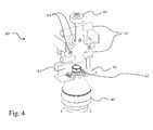
- a trolley 60 with passive gripping system 61 and transfer opening 63 is in FIG. 4 shown.
- the firm and secure locking of the bottle 40 in the passive gripping system 61 is ensured by means of tensioned springs 62.
- the trolley 60 is guided by means of rollers 64 in the guide system 54 of the container transport device 24a or 24b.
- the single roller 65 serves to guide the trolley 60 through the sawtooth star 50, 52 at the transfer points.
- FIG. 5 shows the transfer of a bottle 40 from the outlet star 30 to a trolley 60.
- the active clip 31 of the outlet star 30 opens by curve control at the transfer point and the bottle 40 is by a passive gripping system 61 of a trolley 60 taken over.
- the holding jaws 91 of the active clip 31 engage in the transfer opening 63 of the trolley 60.
- the gripper jaws 91 of the active bracket 31 By actively opening the gripper jaws 91 of the active bracket 31, the bottle 40 is released and taken over by the trolley 60. The active clamp 31 is then pulled out of the transfer opening 63, while the bottle 40 remains in the trolley 60.
- FIG. 5 the transfer of a bottle 40 from the trolley 60 to the inlet star 32, ie the figure illustrates that the trolley 60 can be loaded or unloaded from two opposite sides.
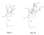
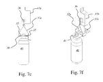
- FIGS. 6a to 7f show embodiments for active staples 34, which can be found, for example, on an outlet star 30 or on an inlet star 32 use.
- This is a gripping system, which is mainly suitable to grip PET bottles 40 or other plastic containers with support ring 41.
- the clamp / gripper 34 consists of at least one guide roller 36, a holder 37, as well as hinges 38 movable gripper jaws 35.
- the hinges 38 may be, for example, pivot bearing.
- the peculiarity here lies in the mechanically or magnetically “controlled” opening mechanism and in the closed position held by the weight of the bottle 40.
- the gripper jaws 35 of the bracket 34 are made of ferromagnetic material.
- the present grippers 34 are simple. They consist of a double roller 36, a holder 37a, a connection to the chain link 37b and two hinges 38, over which the gripper jaws 35 are moved. Instead of a double roller 36, for example, a single role can be used. If necessary, this very cost-effective design must be supplemented by attachments on the contact surfaces for a gentler handling and by the guide rails and bracket.
- brackets 34 In order to be able to react to the most varied and smallest shoulder heights of the bottles 40 and / or to a different position of the support ring 41, for example at shoulder height, it is still possible to provide the brackets 34 with an additional height offset of the brackets 34 in order to minimize the pivoting movement. " just "to hold. The magnets could then also be arranged laterally in this case.
- the bracket 34 may have an opening 39 corresponding to the width of the neck of the bottle 40 to be transported.
- the clamp 34 has different openings 39a / 39b / 39c with different opening widths, so that different bottles or containers with different neck widths can be transported.
- brackets 34 are partially actively controlled.
- either the controlled opening or closing can be dispensed with.
- This is achieved by arranging either at least one tension spring or at least one compression spring between the gripping jaws 35 or the holder 37 a.
- the jaws can be closed automatically with a compression spring and only have to be actively opened. If one has at least one tension spring between the gripping jaws 35 and the holder 37 a arranges, the bracket 34 only has to be closed. Depending on the strength of the spring can then hold the bottle closed by their weight force the clip.
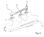
- FIG. 8 The situation at the outlet of the bottles 40 from the blow molding machine 20 is in FIG. 8 shown.
- the gripper / clamp 34 descends from above onto the bottle 40, which is simultaneously conveyed on a conveyor belt.
- the bottle 40 must be supported from below so that the gripper jaws 35 of the clip 34 can spread over the bottle.
- the gripper jaws 35 then open by contact with the neck ring 41 itself.
- the opening 39 is large enough to fit over the support ring 41 of the bottle 40.
- the bracket 34 is lowered further down until the gripper jaws 35 are finally below the support ring 41 and are pulled down by a magnet or by their own weight.
- the gripper jaws 35 are closed again and dig in at a slight start up by means of the guide rails below the support ring 41 a. Afterwards the transport can take place.
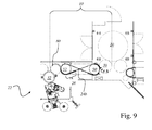
- FIG. 9 shows a schematic arrangement of a arranged between a blow molding machine 20 and a labeling machine 22 container transfer system with crossed carriage guide 24b.
- the bottles 40 produced in the blow molding machine 20 are connected via a discharge star 30 to a sawtooth star 50 of a Handed container transfer system 24b and transported to the sawtooth star 52, where they are passed to a neck handling system 80 and then to the inlet star 32 of the labeling device 22.
- this system thus comes out with only one neck handling system 80.
- the system finds particular use when the labeling device 22 has a different direction than in the case of FIG. 1 is needed.
- FIG. 10 shows a detailed view of the container transfer system with crossed carriage guide 24b.
- the container transfer system 24b also consists of two sawtooth stars 50, 52 which are interconnected by a guide system 54.
- the guide system 54 consists of two parallel guide rails and is crossed, so that the sawtooth stars 50, 52 have opposite directions of running.
- the container transfer system 24b is thus used when an outflow star 30 and an infeed starter 32 or a neck handling system 80 are used in the opposite direction.
- the guide system 54 is formed staged due to the crossover, the rails 54, in which the empty transport units 60 are transported back to the first transfer unit / first sawtooth star 50, are guided over the rails 54, in which loaded with containers 40 transport units 60 of the first transfer unit 50 are transported to the second sawtooth star 52.
- the transport carriages rotate 180 degrees before transfer to the infeed starter 32 of the labeller 22 or before transfer to a neck handling system 80 so that their retaining clips 33 engage in the transport carriage 60 from the opposite direction to take over the bottle 40.
- the direction of travel of the dispensed bottles 40 corresponds to the running direction of the inlet star 32 of the labeling device 22, so that one of the intermediate stars can be dispensed with.
Landscapes
- Engineering & Computer Science (AREA)
- Mechanical Engineering (AREA)
- Specific Conveyance Elements (AREA)
- Labeling Devices (AREA)
- Control Of Conveyors (AREA)
Applications Claiming Priority (1)
| Application Number | Priority Date | Filing Date | Title |
|---|---|---|---|
| DE200910044104 DE102009044104A1 (de) | 2009-09-24 | 2009-09-24 | Einrichtung zum Transfer von Behältern zwischen zwei Bearbeitungsstationen sowie ein Verfahren zum Transfer von Behältern zwischen zwei Bearbeitungsstationen |
Publications (3)
| Publication Number | Publication Date |
|---|---|
| EP2301867A2 true EP2301867A2 (fr) | 2011-03-30 |
| EP2301867A3 EP2301867A3 (fr) | 2014-02-26 |
| EP2301867B1 EP2301867B1 (fr) | 2018-06-06 |
Family
ID=43332870
Family Applications (1)
| Application Number | Title | Priority Date | Filing Date |
|---|---|---|---|
| EP10174380.5A Active EP2301867B1 (fr) | 2009-09-24 | 2010-08-27 | Dispositif de transfert de récipients entre deux stations de traitement et procédé de transfert de récipients entre deux stations de traitement |
Country Status (3)
| Country | Link |
|---|---|
| EP (1) | EP2301867B1 (fr) |
| CN (1) | CN102030182B (fr) |
| DE (1) | DE102009044104A1 (fr) |
Cited By (10)
| Publication number | Priority date | Publication date | Assignee | Title |
|---|---|---|---|---|
| WO2011131704A1 (fr) * | 2010-04-22 | 2011-10-27 | Krones Ag | Dispositif de transport et procédé de transport pour installation de traitement de contenants, et installation de traitement de contenants dotée d'un tel dispositif de transport |
| WO2013079244A1 (fr) * | 2011-11-28 | 2013-06-06 | Krones Aktiengesellschaft | Procédé et système d'ordonnancement de plusieurs articles se déplaçant dans un flux massique |
| ITTO20111145A1 (it) * | 2011-12-13 | 2013-06-14 | Sidel Spa Con Socio Unico | Dispositivo convogliatore per articoli ed impianto di trattamento di tali articoli comprendente il suddetto dispositivo convogliatore |
| CH709352A1 (de) * | 2014-03-11 | 2015-09-15 | Ferag Ag | Fördervorrichtung mit entlang einer Förderbahn mittels Mitnehmern einzeln bewegbaren Förderwagen, zugehörige Abgabeeinrichtung und Verfahren. |
| EP3044136B1 (fr) | 2013-09-13 | 2017-07-05 | Krones AG | Appareil et procédé pour grouper des récipients |
| US10252828B2 (en) | 2014-07-31 | 2019-04-09 | Sidel S.P.A. Con Socio Unico | Plant for the filling and capping of containers, in particular bottles |
| EP3753900A1 (fr) * | 2019-05-22 | 2020-12-23 | Krones Ag | Dispositif de maintien d'un récipient et dispositif de fermeture |
| US20230085671A1 (en) * | 2021-09-20 | 2023-03-23 | Quest Industrial LLC | System and method for handling and evaluating products packaged in flexible bags |
| EP4538204A1 (fr) * | 2023-10-12 | 2025-04-16 | Dürkopp Fördertechnik GmbH | Dispositif de transport suspendu, installation de transport suspendu dotée d'un tel dispositif de transport suspendu et procédé de transport de marchandises |
| US12709484B2 (en) | 2022-05-24 | 2026-08-18 | Dürkopp Fördertechnik GmbH | Conveying apparatus and conveying method for goods |
Families Citing this family (6)
| Publication number | Priority date | Publication date | Assignee | Title |
|---|---|---|---|---|
| DE102010064545B8 (de) * | 2010-05-20 | 2015-10-01 | Krones Aktiengesellschaft | Heizstrecke zur erwärmung von vorformlingen sowie verfahren zum transportieren von vorformlingen durch eine heizstrecke |
| CN103817037A (zh) * | 2014-03-20 | 2014-05-28 | 浙江明泉工业涂装有限公司 | 涂装设备用喷头结构 |
| EP3109189B1 (fr) * | 2015-06-25 | 2018-10-31 | Sidel Participations | Dispositif de transfert pour transporter des unités d'emballage |
| CN105346744B (zh) * | 2015-12-16 | 2018-03-16 | 长沙汇一制药机械有限公司 | 一种大输液塑料瓶传送装置 |
| DE102017130036A1 (de) * | 2017-12-14 | 2019-06-19 | Krones Ag | Vorrichtung zum Transportieren eines Behälters |
| BE1028746B1 (nl) * | 2020-10-27 | 2022-05-24 | Anheuser Busch Inbev | Een systeem voor het hanteren van afzonderlijke primaire verpakkingshouders |
Citations (4)
| Publication number | Priority date | Publication date | Assignee | Title |
|---|---|---|---|---|
| US5996322A (en) | 1995-03-23 | 1999-12-07 | Sidel | In-line bottling plant |
| DE19928325A1 (de) | 1999-06-21 | 2000-12-28 | Krones Ag | Abfüllvorrichtung für Flaschen |
| DE102006013800B3 (de) | 2006-03-24 | 2007-08-09 | Khs Ag | Transportsystem für Flaschen oder dergleichen Behälter sowie Anlage zum Behandeln von Flaschen oder dergleichen Behälter |
| EP1107588B1 (fr) | 1999-11-30 | 2013-01-09 | Panasonic Corporation | Appareil d'enregistrement de programme et moyen d'enregistrement de programme |
Family Cites Families (16)
| Publication number | Priority date | Publication date | Assignee | Title |
|---|---|---|---|---|
| IT1236279B (it) * | 1989-11-08 | 1993-02-02 | Pro Co Mac Srl | Accumulatore ordinato di bottiglie di materiale plastico. |
| FR2669311B1 (fr) * | 1990-11-15 | 1993-03-05 | Neu Ets | Dispositif d'accumulation dynamique de recipients dans une chaine de transfert par jets d'air. |
| DE19824846A1 (de) * | 1998-06-04 | 1999-12-09 | Khs Masch & Anlagenbau Ag | Anlage zum Abfüllen von flüssigem Füllgut |
| FR2803835B1 (fr) * | 2000-01-14 | 2002-04-19 | Rafale Technologie | Procede et dispositif de convoyage d'objets en position suspendue |
| DE10040532A1 (de) * | 2000-08-18 | 2002-02-28 | Khs Masch & Anlagenbau Ag | Fördervorrichtung zum Transportieren von Behältern |
| FR2815621B1 (fr) * | 2000-10-23 | 2003-01-10 | Sidel Sa | Dispositif de retournement de corps creux |
| EP1295820B1 (fr) * | 2001-09-20 | 2005-11-30 | Sig Simonazzi S.P.A. | Dispositif de stockage temporaire d'articles dans une chaine de production |
| DE10329785B4 (de) * | 2003-07-01 | 2006-12-21 | Krones Ag | Vorrichtung zum Transport von Behältern |
| DE102004053663A1 (de) * | 2004-02-02 | 2005-08-18 | Krones Ag | Vorrichtung zum dynamischen Speichern von Gegenständen |
| DE102004048515A1 (de) * | 2004-10-06 | 2006-04-13 | Krones Ag | Sortiervorrichtung und Fördervorrichtung für Stückgut sowie Verfahren zum Sortieren oder Fördern von Stückgut |
| DE202005013552U1 (de) * | 2005-08-27 | 2005-11-03 | Krones Ag | Dynamischer Speicher für Gegenstände |
| DE102006047848A1 (de) * | 2006-10-10 | 2008-04-17 | Krones Ag | Vorrichtung zm Auffüllen von Lücken |
| DE102006056943A1 (de) * | 2006-11-30 | 2008-06-12 | A20 Ag | Verfahren zum Transport von Gegenständen |
| DE102008013951A1 (de) * | 2008-03-12 | 2009-09-17 | Nov Hau Ag Engineering | Verfahren und Vorrichtung zum Transport und/oder Speichern von Gegenständen |
| DE102008020117A1 (de) * | 2008-04-22 | 2009-10-29 | Krones Ag | Träger und Verfahren zum Transportieren eines Behälters |
| DE102008037865A1 (de) * | 2008-08-15 | 2010-02-18 | Anton Jazbinsek | Transportvorrichtung |
-
2009
- 2009-09-24 DE DE200910044104 patent/DE102009044104A1/de not_active Ceased
-
2010
- 2010-08-27 EP EP10174380.5A patent/EP2301867B1/fr active Active
- 2010-09-21 CN CN201010295698.6A patent/CN102030182B/zh active Active
Patent Citations (4)
| Publication number | Priority date | Publication date | Assignee | Title |
|---|---|---|---|---|
| US5996322A (en) | 1995-03-23 | 1999-12-07 | Sidel | In-line bottling plant |
| DE19928325A1 (de) | 1999-06-21 | 2000-12-28 | Krones Ag | Abfüllvorrichtung für Flaschen |
| EP1107588B1 (fr) | 1999-11-30 | 2013-01-09 | Panasonic Corporation | Appareil d'enregistrement de programme et moyen d'enregistrement de programme |
| DE102006013800B3 (de) | 2006-03-24 | 2007-08-09 | Khs Ag | Transportsystem für Flaschen oder dergleichen Behälter sowie Anlage zum Behandeln von Flaschen oder dergleichen Behälter |
Cited By (20)
| Publication number | Priority date | Publication date | Assignee | Title |
|---|---|---|---|---|
| WO2011131704A1 (fr) * | 2010-04-22 | 2011-10-27 | Krones Ag | Dispositif de transport et procédé de transport pour installation de traitement de contenants, et installation de traitement de contenants dotée d'un tel dispositif de transport |
| US9233800B2 (en) | 2010-04-22 | 2016-01-12 | Krones Ag | Transporting apparatus and transporting method for container-handling installation, and container-handling installation with such a transporting apparatus |
| EP3778439A1 (fr) * | 2010-04-22 | 2021-02-17 | Krones Ag | Dispositif de transport et procédé de transport pour l'installation de traitement des récipients ainsi qu'installation de traitement des récipients dotée d'un tel dispositif de transport |
| EP2560903B1 (fr) | 2010-04-22 | 2017-06-07 | Krones AG | Dispositif de transport et procédé de transport pour installation de traitement de contenants, et installation de traitement de contenants dotée d'un tel dispositif de transport |
| EP3181495A1 (fr) * | 2010-04-22 | 2017-06-21 | Krones Ag | Dispositif de transport et procédé de transport d'installation de traitement de récipients et installation de traitement de récipients comprenant un tel dispositif de transport |
| WO2013079244A1 (fr) * | 2011-11-28 | 2013-06-06 | Krones Aktiengesellschaft | Procédé et système d'ordonnancement de plusieurs articles se déplaçant dans un flux massique |
| US9579693B2 (en) | 2011-11-28 | 2017-02-28 | Krones Aktiengesellschaft | Method and system for arranging a plurality of articles moved in a mass flow |
| ITTO20111145A1 (it) * | 2011-12-13 | 2013-06-14 | Sidel Spa Con Socio Unico | Dispositivo convogliatore per articoli ed impianto di trattamento di tali articoli comprendente il suddetto dispositivo convogliatore |
| EP2604553A1 (fr) * | 2011-12-13 | 2013-06-19 | Sidel S.p.a. Con Socio Unico | Dispositif de transport d'articles et installation pour la manipulation de ces articles comprenant ledit dispositif de transport |
| US8657101B2 (en) | 2011-12-13 | 2014-02-25 | Sidel S.P.A. Con Socio Unico | Conveying apparatus for articles and plant for handling such articles comprising said conveying appartus |
| EP3044136B1 (fr) | 2013-09-13 | 2017-07-05 | Krones AG | Appareil et procédé pour grouper des récipients |
| CH709352A1 (de) * | 2014-03-11 | 2015-09-15 | Ferag Ag | Fördervorrichtung mit entlang einer Förderbahn mittels Mitnehmern einzeln bewegbaren Förderwagen, zugehörige Abgabeeinrichtung und Verfahren. |
| US9394118B2 (en) | 2014-03-11 | 2016-07-19 | Ferag Ag | Method and device for discharging piece goods from a conveying apparatus |
| US10252828B2 (en) | 2014-07-31 | 2019-04-09 | Sidel S.P.A. Con Socio Unico | Plant for the filling and capping of containers, in particular bottles |
| EP3753900A1 (fr) * | 2019-05-22 | 2020-12-23 | Krones Ag | Dispositif de maintien d'un récipient et dispositif de fermeture |
| US11772949B2 (en) | 2019-05-22 | 2023-10-03 | Krones Ag | Device for holding a container and closing device |
| US20230085671A1 (en) * | 2021-09-20 | 2023-03-23 | Quest Industrial LLC | System and method for handling and evaluating products packaged in flexible bags |
| US12024372B2 (en) * | 2021-09-20 | 2024-07-02 | Quest Industrial LLC | System and method for handling and evaluating products packaged in flexible bags |
| US12709484B2 (en) | 2022-05-24 | 2026-08-18 | Dürkopp Fördertechnik GmbH | Conveying apparatus and conveying method for goods |
| EP4538204A1 (fr) * | 2023-10-12 | 2025-04-16 | Dürkopp Fördertechnik GmbH | Dispositif de transport suspendu, installation de transport suspendu dotée d'un tel dispositif de transport suspendu et procédé de transport de marchandises |
Also Published As
| Publication number | Publication date |
|---|---|
| DE102009044104A1 (de) | 2011-03-31 |
| EP2301867A3 (fr) | 2014-02-26 |
| EP2301867B1 (fr) | 2018-06-06 |
| CN102030182A (zh) | 2011-04-27 |
| CN102030182B (zh) | 2014-09-10 |
Similar Documents
| Publication | Publication Date | Title |
|---|---|---|
| EP2301867B1 (fr) | Dispositif de transfert de récipients entre deux stations de traitement et procédé de transfert de récipients entre deux stations de traitement | |
| EP3237892B1 (fr) | Dispositif et procédé d'inspection en continu de récipients | |
| EP2560903B1 (fr) | Dispositif de transport et procédé de transport pour installation de traitement de contenants, et installation de traitement de contenants dotée d'un tel dispositif de transport | |
| EP2784009B1 (fr) | Procédé et dispositif de transfert de marchandises au détail au niveau d'une installation de transport | |
| EP2295352B1 (fr) | Dispositif de prise pour tenir et déplacer des articles | |
| EP2918520B1 (fr) | Procédé et dispositif de distribution de marchandises au détail à partir d'un dispositif de transport | |
| EP2465814B1 (fr) | Dispositif de fabrication de récipients en plastique | |
| DE102010018216B4 (de) | Behältnisbehandlungsanlage mit änderbarer Beladung | |
| DE102013112091A1 (de) | Vorrichtung zur Aufgabe und/oder Entnahme von Objekten auf eine und/oder von einer Behandlungsmaschine | |
| EP3354603A1 (fr) | Dispositif et procédé de déplacement d'éléments transporteurs dans une installation de manutention de récipients | |
| CH707798A1 (de) | Schienengeführtes Fördermittel und Förderanlage mit derartigen Fördermitteln. | |
| EP1901982A1 (fr) | Machine pour le traitement de recipients | |
| EP2734463A1 (fr) | Module permettant d'aligner des récipients et procédé permettant d'aligner des récipients | |
| EP4045440B1 (fr) | Dispositif et procédé de transport d'objets | |
| EP3558833B1 (fr) | Dispositif d'étiquetage et procédé d'application d'étiquettes sur des récipients | |
| DE102006056943A1 (de) | Verfahren zum Transport von Gegenständen | |
| EP2307293B1 (fr) | Procédé pour manipuler des contenants pendant leur transport dans des installations de remplissage | |
| DE102020131105A1 (de) | Vorrichtung zum linearen Transportieren von Behältern | |
| DE102016109226A1 (de) | Vorrichtung und Verfahren zum definierten Vereinigen, Verteilen und/oder Umverteilen von Stückgut und/oder Stückgutgruppen | |
| EP3450355A1 (fr) | Installation de transport | |
| WO2025062196A1 (fr) | Dispositif, procédé et système de stabilisation et de chargement de sacs de transport | |
| EP2733091B1 (fr) | Dispositif d'acheminement d'au moins une pièce moulée dans une installation de remplissage de boissons | |
| EP3315456B1 (fr) | Dispositif destiné à verrouiller des bouteilles munies de fermeture à étrier | |
| EP4240678A1 (fr) | Dispositif de transport pour le transport de récipients | |
| DE102017130352A1 (de) | Vorrichtung und Verfahren zum Transportieren von Packungen |
Legal Events
| Date | Code | Title | Description |
|---|---|---|---|
| PUAI | Public reference made under article 153(3) epc to a published international application that has entered the european phase |
Free format text: ORIGINAL CODE: 0009012 |
|
| AK | Designated contracting states |
Kind code of ref document: A2 Designated state(s): AL AT BE BG CH CY CZ DE DK EE ES FI FR GB GR HR HU IE IS IT LI LT LU LV MC MK MT NL NO PL PT RO SE SI SK SM TR |
|
| AX | Request for extension of the european patent |
Extension state: BA ME RS |
|
| RIC1 | Information provided on ipc code assigned before grant |
Ipc: B65G 35/08 20060101ALI20131106BHEP Ipc: B65G 19/02 20060101ALI20131106BHEP Ipc: B65G 47/51 20060101AFI20131106BHEP |
|
| PUAL | Search report despatched |
Free format text: ORIGINAL CODE: 0009013 |
|
| AK | Designated contracting states |
Kind code of ref document: A3 Designated state(s): AL AT BE BG CH CY CZ DE DK EE ES FI FR GB GR HR HU IE IS IT LI LT LU LV MC MK MT NL NO PL PT RO SE SI SK SM TR |
|
| AX | Request for extension of the european patent |
Extension state: BA ME RS |
|
| RIC1 | Information provided on ipc code assigned before grant |
Ipc: B65G 47/51 20060101AFI20140121BHEP Ipc: B65G 19/02 20060101ALI20140121BHEP Ipc: B65G 35/08 20060101ALI20140121BHEP |
|
| 17P | Request for examination filed |
Effective date: 20140707 |
|
| RBV | Designated contracting states (corrected) |
Designated state(s): AL AT BE BG CH CY CZ DE DK EE ES FI FR GB GR HR HU IE IS IT LI LT LU LV MC MK MT NL NO PL PT RO SE SI SK SM TR |
|
| RIN1 | Information on inventor provided before grant (corrected) |
Inventor name: WEISS, JOHANNES Inventor name: WINZINGER, FRANK Inventor name: HAUSLADEN, WOLFGANG |
|
| 17Q | First examination report despatched |
Effective date: 20140828 |
|
| GRAP | Despatch of communication of intention to grant a patent |
Free format text: ORIGINAL CODE: EPIDOSNIGR1 |
|
| INTG | Intention to grant announced |
Effective date: 20180119 |
|
| GRAS | Grant fee paid |
Free format text: ORIGINAL CODE: EPIDOSNIGR3 |
|
| GRAA | (expected) grant |
Free format text: ORIGINAL CODE: 0009210 |
|
| AK | Designated contracting states |
Kind code of ref document: B1 Designated state(s): AL AT BE BG CH CY CZ DE DK EE ES FI FR GB GR HR HU IE IS IT LI LT LU LV MC MK MT NL NO PL PT RO SE SI SK SM TR |
|
| REG | Reference to a national code |
Ref country code: GB Ref legal event code: FG4D Free format text: NOT ENGLISH |
|
| REG | Reference to a national code |
Ref country code: CH Ref legal event code: EP Ref country code: AT Ref legal event code: REF Ref document number: 1005856 Country of ref document: AT Kind code of ref document: T Effective date: 20180615 |
|
| REG | Reference to a national code |
Ref country code: IE Ref legal event code: FG4D Free format text: LANGUAGE OF EP DOCUMENT: GERMAN |
|
| REG | Reference to a national code |
Ref country code: DE Ref legal event code: R096 Ref document number: 502010015047 Country of ref document: DE |
|
| REG | Reference to a national code |
Ref country code: FR Ref legal event code: PLFP Year of fee payment: 9 |
|
| REG | Reference to a national code |
Ref country code: NL Ref legal event code: MP Effective date: 20180606 |
|
| REG | Reference to a national code |
Ref country code: LT Ref legal event code: MG4D |
|
| PG25 | Lapsed in a contracting state [announced via postgrant information from national office to epo] |
Ref country code: CY Free format text: LAPSE BECAUSE OF FAILURE TO SUBMIT A TRANSLATION OF THE DESCRIPTION OR TO PAY THE FEE WITHIN THE PRESCRIBED TIME-LIMIT Effective date: 20180606 Ref country code: LT Free format text: LAPSE BECAUSE OF FAILURE TO SUBMIT A TRANSLATION OF THE DESCRIPTION OR TO PAY THE FEE WITHIN THE PRESCRIBED TIME-LIMIT Effective date: 20180606 Ref country code: SE Free format text: LAPSE BECAUSE OF FAILURE TO SUBMIT A TRANSLATION OF THE DESCRIPTION OR TO PAY THE FEE WITHIN THE PRESCRIBED TIME-LIMIT Effective date: 20180606 Ref country code: FI Free format text: LAPSE BECAUSE OF FAILURE TO SUBMIT A TRANSLATION OF THE DESCRIPTION OR TO PAY THE FEE WITHIN THE PRESCRIBED TIME-LIMIT Effective date: 20180606 Ref country code: BG Free format text: LAPSE BECAUSE OF FAILURE TO SUBMIT A TRANSLATION OF THE DESCRIPTION OR TO PAY THE FEE WITHIN THE PRESCRIBED TIME-LIMIT Effective date: 20180906 Ref country code: NO Free format text: LAPSE BECAUSE OF FAILURE TO SUBMIT A TRANSLATION OF THE DESCRIPTION OR TO PAY THE FEE WITHIN THE PRESCRIBED TIME-LIMIT Effective date: 20180906 Ref country code: ES Free format text: LAPSE BECAUSE OF FAILURE TO SUBMIT A TRANSLATION OF THE DESCRIPTION OR TO PAY THE FEE WITHIN THE PRESCRIBED TIME-LIMIT Effective date: 20180606 |
|
| PG25 | Lapsed in a contracting state [announced via postgrant information from national office to epo] |
Ref country code: GR Free format text: LAPSE BECAUSE OF FAILURE TO SUBMIT A TRANSLATION OF THE DESCRIPTION OR TO PAY THE FEE WITHIN THE PRESCRIBED TIME-LIMIT Effective date: 20180907 Ref country code: HR Free format text: LAPSE BECAUSE OF FAILURE TO SUBMIT A TRANSLATION OF THE DESCRIPTION OR TO PAY THE FEE WITHIN THE PRESCRIBED TIME-LIMIT Effective date: 20180606 Ref country code: LV Free format text: LAPSE BECAUSE OF FAILURE TO SUBMIT A TRANSLATION OF THE DESCRIPTION OR TO PAY THE FEE WITHIN THE PRESCRIBED TIME-LIMIT Effective date: 20180606 |
|
| PG25 | Lapsed in a contracting state [announced via postgrant information from national office to epo] |
Ref country code: NL Free format text: LAPSE BECAUSE OF FAILURE TO SUBMIT A TRANSLATION OF THE DESCRIPTION OR TO PAY THE FEE WITHIN THE PRESCRIBED TIME-LIMIT Effective date: 20180606 |
|
| PG25 | Lapsed in a contracting state [announced via postgrant information from national office to epo] |
Ref country code: RO Free format text: LAPSE BECAUSE OF FAILURE TO SUBMIT A TRANSLATION OF THE DESCRIPTION OR TO PAY THE FEE WITHIN THE PRESCRIBED TIME-LIMIT Effective date: 20180606 Ref country code: CZ Free format text: LAPSE BECAUSE OF FAILURE TO SUBMIT A TRANSLATION OF THE DESCRIPTION OR TO PAY THE FEE WITHIN THE PRESCRIBED TIME-LIMIT Effective date: 20180606 Ref country code: SK Free format text: LAPSE BECAUSE OF FAILURE TO SUBMIT A TRANSLATION OF THE DESCRIPTION OR TO PAY THE FEE WITHIN THE PRESCRIBED TIME-LIMIT Effective date: 20180606 Ref country code: EE Free format text: LAPSE BECAUSE OF FAILURE TO SUBMIT A TRANSLATION OF THE DESCRIPTION OR TO PAY THE FEE WITHIN THE PRESCRIBED TIME-LIMIT Effective date: 20180606 Ref country code: PL Free format text: LAPSE BECAUSE OF FAILURE TO SUBMIT A TRANSLATION OF THE DESCRIPTION OR TO PAY THE FEE WITHIN THE PRESCRIBED TIME-LIMIT Effective date: 20180606 Ref country code: IS Free format text: LAPSE BECAUSE OF FAILURE TO SUBMIT A TRANSLATION OF THE DESCRIPTION OR TO PAY THE FEE WITHIN THE PRESCRIBED TIME-LIMIT Effective date: 20181006 |
|
| PG25 | Lapsed in a contracting state [announced via postgrant information from national office to epo] |
Ref country code: SM Free format text: LAPSE BECAUSE OF FAILURE TO SUBMIT A TRANSLATION OF THE DESCRIPTION OR TO PAY THE FEE WITHIN THE PRESCRIBED TIME-LIMIT Effective date: 20180606 |
|
| REG | Reference to a national code |
Ref country code: DE Ref legal event code: R097 Ref document number: 502010015047 Country of ref document: DE |
|
| PG25 | Lapsed in a contracting state [announced via postgrant information from national office to epo] |
Ref country code: MC Free format text: LAPSE BECAUSE OF FAILURE TO SUBMIT A TRANSLATION OF THE DESCRIPTION OR TO PAY THE FEE WITHIN THE PRESCRIBED TIME-LIMIT Effective date: 20180606 |
|
| REG | Reference to a national code |
Ref country code: CH Ref legal event code: PL |
|
| PLBE | No opposition filed within time limit |
Free format text: ORIGINAL CODE: 0009261 |
|
| STAA | Information on the status of an ep patent application or granted ep patent |
Free format text: STATUS: NO OPPOSITION FILED WITHIN TIME LIMIT |
|
| PG25 | Lapsed in a contracting state [announced via postgrant information from national office to epo] |
Ref country code: LU Free format text: LAPSE BECAUSE OF NON-PAYMENT OF DUE FEES Effective date: 20180827 Ref country code: LI Free format text: LAPSE BECAUSE OF NON-PAYMENT OF DUE FEES Effective date: 20180831 Ref country code: CH Free format text: LAPSE BECAUSE OF NON-PAYMENT OF DUE FEES Effective date: 20180831 |
|
| REG | Reference to a national code |
Ref country code: BE Ref legal event code: MM Effective date: 20180831 |
|
| 26N | No opposition filed |
Effective date: 20190307 |
|
| GBPC | Gb: european patent ceased through non-payment of renewal fee |
Effective date: 20180906 |
|
| PG25 | Lapsed in a contracting state [announced via postgrant information from national office to epo] |
Ref country code: SI Free format text: LAPSE BECAUSE OF FAILURE TO SUBMIT A TRANSLATION OF THE DESCRIPTION OR TO PAY THE FEE WITHIN THE PRESCRIBED TIME-LIMIT Effective date: 20180606 Ref country code: DK Free format text: LAPSE BECAUSE OF FAILURE TO SUBMIT A TRANSLATION OF THE DESCRIPTION OR TO PAY THE FEE WITHIN THE PRESCRIBED TIME-LIMIT Effective date: 20180606 |
|
| PG25 | Lapsed in a contracting state [announced via postgrant information from national office to epo] |
Ref country code: BE Free format text: LAPSE BECAUSE OF NON-PAYMENT OF DUE FEES Effective date: 20180831 |
|
| REG | Reference to a national code |
Ref country code: AT Ref legal event code: MM01 Ref document number: 1005856 Country of ref document: AT Kind code of ref document: T Effective date: 20180827 |
|
| PG25 | Lapsed in a contracting state [announced via postgrant information from national office to epo] |
Ref country code: GB Free format text: LAPSE BECAUSE OF NON-PAYMENT OF DUE FEES Effective date: 20180906 |
|
| PG25 | Lapsed in a contracting state [announced via postgrant information from national office to epo] |
Ref country code: AL Free format text: LAPSE BECAUSE OF FAILURE TO SUBMIT A TRANSLATION OF THE DESCRIPTION OR TO PAY THE FEE WITHIN THE PRESCRIBED TIME-LIMIT Effective date: 20180606 |
|
| PG25 | Lapsed in a contracting state [announced via postgrant information from national office to epo] |
Ref country code: AT Free format text: LAPSE BECAUSE OF NON-PAYMENT OF DUE FEES Effective date: 20180827 |
|
| PG25 | Lapsed in a contracting state [announced via postgrant information from national office to epo] |
Ref country code: MT Free format text: LAPSE BECAUSE OF FAILURE TO SUBMIT A TRANSLATION OF THE DESCRIPTION OR TO PAY THE FEE WITHIN THE PRESCRIBED TIME-LIMIT Effective date: 20180606 |
|
| PG25 | Lapsed in a contracting state [announced via postgrant information from national office to epo] |
Ref country code: TR Free format text: LAPSE BECAUSE OF FAILURE TO SUBMIT A TRANSLATION OF THE DESCRIPTION OR TO PAY THE FEE WITHIN THE PRESCRIBED TIME-LIMIT Effective date: 20180606 |
|
| PG25 | Lapsed in a contracting state [announced via postgrant information from national office to epo] |
Ref country code: HU Free format text: LAPSE BECAUSE OF FAILURE TO SUBMIT A TRANSLATION OF THE DESCRIPTION OR TO PAY THE FEE WITHIN THE PRESCRIBED TIME-LIMIT; INVALID AB INITIO Effective date: 20100827 Ref country code: PT Free format text: LAPSE BECAUSE OF FAILURE TO SUBMIT A TRANSLATION OF THE DESCRIPTION OR TO PAY THE FEE WITHIN THE PRESCRIBED TIME-LIMIT Effective date: 20180606 |
|
| PG25 | Lapsed in a contracting state [announced via postgrant information from national office to epo] |
Ref country code: MK Free format text: LAPSE BECAUSE OF NON-PAYMENT OF DUE FEES Effective date: 20180606 Ref country code: IE Free format text: LAPSE BECAUSE OF NON-PAYMENT OF DUE FEES Effective date: 20180827 |
|
| P01 | Opt-out of the competence of the unified patent court (upc) registered |
Effective date: 20230523 |
|
| REG | Reference to a national code |
Ref country code: DE Ref legal event code: R082 Ref document number: 502010015047 Country of ref document: DE Representative=s name: BENNINGER, JOHANNES, DIPL.-ING., DE |
|
| PGFP | Annual fee paid to national office [announced via postgrant information from national office to epo] |
Ref country code: DE Payment date: 20250702 Year of fee payment: 16 |
|
| PGFP | Annual fee paid to national office [announced via postgrant information from national office to epo] |
Ref country code: IT Payment date: 20250722 Year of fee payment: 16 |
|
| PGFP | Annual fee paid to national office [announced via postgrant information from national office to epo] |
Ref country code: FR Payment date: 20250703 Year of fee payment: 16 |