EP2301875A1 - Dispositif de découpe et de transfert fonctionnant par intermittence - Google Patents
Dispositif de découpe et de transfert fonctionnant par intermittence Download PDFInfo
- Publication number
- EP2301875A1 EP2301875A1 EP09773459A EP09773459A EP2301875A1 EP 2301875 A1 EP2301875 A1 EP 2301875A1 EP 09773459 A EP09773459 A EP 09773459A EP 09773459 A EP09773459 A EP 09773459A EP 2301875 A1 EP2301875 A1 EP 2301875A1
- Authority
- EP
- European Patent Office
- Prior art keywords
- film sheet
- suction
- blade roll
- lower blade
- cut
- Prior art date
- Legal status (The legal status is an assumption and is not a legal conclusion. Google has not performed a legal analysis and makes no representation as to the accuracy of the status listed.)
- Granted
Links
Images


Classifications
-
- B—PERFORMING OPERATIONS; TRANSPORTING
- B65—CONVEYING; PACKING; STORING; HANDLING THIN OR FILAMENTARY MATERIAL
- B65H—HANDLING THIN OR FILAMENTARY MATERIAL, e.g. SHEETS, WEBS, CABLES
- B65H39/00—Associating, collating, or gathering articles or webs
- B65H39/14—Associating sheets with webs
-
- A—HUMAN NECESSITIES
- A61—MEDICAL OR VETERINARY SCIENCE; HYGIENE
- A61F—FILTERS IMPLANTABLE INTO BLOOD VESSELS; PROSTHESES; DEVICES PROVIDING PATENCY TO, OR PREVENTING COLLAPSING OF, TUBULAR STRUCTURES OF THE BODY, e.g. STENTS; ORTHOPAEDIC, NURSING OR CONTRACEPTIVE DEVICES; FOMENTATION; TREATMENT OR PROTECTION OF EYES OR EARS; BANDAGES, DRESSINGS OR ABSORBENT PADS; FIRST-AID KITS
- A61F13/00—Bandages or dressings; Absorbent pads
- A61F13/15—Absorbent pads, e.g. sanitary towels, swabs or tampons for external or internal application to the body; Supporting or fastening means therefor; Tampon applicators
- A61F13/15577—Apparatus or processes for manufacturing
- A61F13/15707—Mechanical treatment, e.g. notching, twisting, compressing, shaping
- A61F13/15723—Partitioning batts; Cutting
-
- A—HUMAN NECESSITIES
- A61—MEDICAL OR VETERINARY SCIENCE; HYGIENE
- A61F—FILTERS IMPLANTABLE INTO BLOOD VESSELS; PROSTHESES; DEVICES PROVIDING PATENCY TO, OR PREVENTING COLLAPSING OF, TUBULAR STRUCTURES OF THE BODY, e.g. STENTS; ORTHOPAEDIC, NURSING OR CONTRACEPTIVE DEVICES; FOMENTATION; TREATMENT OR PROTECTION OF EYES OR EARS; BANDAGES, DRESSINGS OR ABSORBENT PADS; FIRST-AID KITS
- A61F13/00—Bandages or dressings; Absorbent pads
- A61F13/15—Absorbent pads, e.g. sanitary towels, swabs or tampons for external or internal application to the body; Supporting or fastening means therefor; Tampon applicators
- A61F13/15577—Apparatus or processes for manufacturing
- A61F13/15764—Transferring, feeding or handling devices; Drives
-
- B—PERFORMING OPERATIONS; TRANSPORTING
- B26—HAND CUTTING TOOLS; CUTTING; SEVERING
- B26D—CUTTING; DETAILS COMMON TO MACHINES FOR PERFORATING, PUNCHING, CUTTING-OUT, STAMPING-OUT OR SEVERING
- B26D1/00—Cutting through work characterised by the nature or movement of the cutting member or particular materials not otherwise provided for; Apparatus or machines therefor; Cutting members therefor
- B26D1/01—Cutting through work characterised by the nature or movement of the cutting member or particular materials not otherwise provided for; Apparatus or machines therefor; Cutting members therefor involving a cutting member which does not travel with the work
- B26D1/12—Cutting through work characterised by the nature or movement of the cutting member or particular materials not otherwise provided for; Apparatus or machines therefor; Cutting members therefor involving a cutting member which does not travel with the work having a cutting member moving about an axis
- B26D1/25—Cutting through work characterised by the nature or movement of the cutting member or particular materials not otherwise provided for; Apparatus or machines therefor; Cutting members therefor involving a cutting member which does not travel with the work having a cutting member moving about an axis with a non-circular cutting member
- B26D1/34—Cutting through work characterised by the nature or movement of the cutting member or particular materials not otherwise provided for; Apparatus or machines therefor; Cutting members therefor involving a cutting member which does not travel with the work having a cutting member moving about an axis with a non-circular cutting member moving about an axis parallel to the line of cut
- B26D1/40—Cutting through work characterised by the nature or movement of the cutting member or particular materials not otherwise provided for; Apparatus or machines therefor; Cutting members therefor involving a cutting member which does not travel with the work having a cutting member moving about an axis with a non-circular cutting member moving about an axis parallel to the line of cut and coacting with a rotary member
- B26D1/405—Cutting through work characterised by the nature or movement of the cutting member or particular materials not otherwise provided for; Apparatus or machines therefor; Cutting members therefor involving a cutting member which does not travel with the work having a cutting member moving about an axis with a non-circular cutting member moving about an axis parallel to the line of cut and coacting with a rotary member for thin material, e.g. for sheets, strips or the like
-
- B—PERFORMING OPERATIONS; TRANSPORTING
- B26—HAND CUTTING TOOLS; CUTTING; SEVERING
- B26D—CUTTING; DETAILS COMMON TO MACHINES FOR PERFORATING, PUNCHING, CUTTING-OUT, STAMPING-OUT OR SEVERING
- B26D7/00—Details of apparatus for cutting, cutting-out, stamping-out, punching, perforating, or severing by means other than cutting
- B26D7/01—Means for holding or positioning work
- B26D7/018—Holding the work by suction
-
- B—PERFORMING OPERATIONS; TRANSPORTING
- B65—CONVEYING; PACKING; STORING; HANDLING THIN OR FILAMENTARY MATERIAL
- B65H—HANDLING THIN OR FILAMENTARY MATERIAL, e.g. SHEETS, WEBS, CABLES
- B65H35/00—Delivering articles from cutting or line-perforating machines; Article or web delivery apparatus incorporating cutting or line-perforating devices, e.g. adhesive tape dispensers
- B65H35/04—Delivering articles from cutting or line-perforating machines; Article or web delivery apparatus incorporating cutting or line-perforating devices, e.g. adhesive tape dispensers from or with transverse cutters or perforators
- B65H35/08—Delivering articles from cutting or line-perforating machines; Article or web delivery apparatus incorporating cutting or line-perforating devices, e.g. adhesive tape dispensers from or with transverse cutters or perforators from or with revolving, e.g. cylinder, cutters or perforators
-
- B—PERFORMING OPERATIONS; TRANSPORTING
- B65—CONVEYING; PACKING; STORING; HANDLING THIN OR FILAMENTARY MATERIAL
- B65H—HANDLING THIN OR FILAMENTARY MATERIAL, e.g. SHEETS, WEBS, CABLES
- B65H2301/00—Handling processes for sheets or webs
- B65H2301/10—Selective handling processes
- B65H2301/12—Selective handling processes of sheets or web
- B65H2301/121—Selective handling processes of sheets or web for sheet handling processes, i.e. wherein the web is cut into sheets
-
- B—PERFORMING OPERATIONS; TRANSPORTING
- B65—CONVEYING; PACKING; STORING; HANDLING THIN OR FILAMENTARY MATERIAL
- B65H—HANDLING THIN OR FILAMENTARY MATERIAL, e.g. SHEETS, WEBS, CABLES
- B65H2406/00—Means using fluid
- B65H2406/30—Suction means
- B65H2406/33—Rotary suction means, e.g. roller, cylinder or drum
- B65H2406/332—Details on suction openings
-
- Y—GENERAL TAGGING OF NEW TECHNOLOGICAL DEVELOPMENTS; GENERAL TAGGING OF CROSS-SECTIONAL TECHNOLOGIES SPANNING OVER SEVERAL SECTIONS OF THE IPC; TECHNICAL SUBJECTS COVERED BY FORMER USPC CROSS-REFERENCE ART COLLECTIONS [XRACs] AND DIGESTS
- Y10—TECHNICAL SUBJECTS COVERED BY FORMER USPC
- Y10T—TECHNICAL SUBJECTS COVERED BY FORMER US CLASSIFICATION
- Y10T156/00—Adhesive bonding and miscellaneous chemical manufacture
- Y10T156/12—Surface bonding means and/or assembly means with cutting, punching, piercing, severing or tearing
- Y10T156/125—Plural severing means each acting on a different work piece
-
- Y—GENERAL TAGGING OF NEW TECHNOLOGICAL DEVELOPMENTS; GENERAL TAGGING OF CROSS-SECTIONAL TECHNOLOGIES SPANNING OVER SEVERAL SECTIONS OF THE IPC; TECHNICAL SUBJECTS COVERED BY FORMER USPC CROSS-REFERENCE ART COLLECTIONS [XRACs] AND DIGESTS
- Y10—TECHNICAL SUBJECTS COVERED BY FORMER USPC
- Y10T—TECHNICAL SUBJECTS COVERED BY FORMER US CLASSIFICATION
- Y10T156/00—Adhesive bonding and miscellaneous chemical manufacture
- Y10T156/12—Surface bonding means and/or assembly means with cutting, punching, piercing, severing or tearing
- Y10T156/1317—Means feeding plural workpieces to be joined
- Y10T156/1322—Severing before bonding or assembling of parts
- Y10T156/133—Delivering cut part to indefinite or running length web
-
- Y—GENERAL TAGGING OF NEW TECHNOLOGICAL DEVELOPMENTS; GENERAL TAGGING OF CROSS-SECTIONAL TECHNOLOGIES SPANNING OVER SEVERAL SECTIONS OF THE IPC; TECHNICAL SUBJECTS COVERED BY FORMER USPC CROSS-REFERENCE ART COLLECTIONS [XRACs] AND DIGESTS
- Y10—TECHNICAL SUBJECTS COVERED BY FORMER USPC
- Y10T—TECHNICAL SUBJECTS COVERED BY FORMER US CLASSIFICATION
- Y10T83/00—Cutting
- Y10T83/202—With product handling means
- Y10T83/2066—By fluid current
- Y10T83/207—By suction means
-
- Y—GENERAL TAGGING OF NEW TECHNOLOGICAL DEVELOPMENTS; GENERAL TAGGING OF CROSS-SECTIONAL TECHNOLOGIES SPANNING OVER SEVERAL SECTIONS OF THE IPC; TECHNICAL SUBJECTS COVERED BY FORMER USPC CROSS-REFERENCE ART COLLECTIONS [XRACs] AND DIGESTS
- Y10—TECHNICAL SUBJECTS COVERED BY FORMER USPC
- Y10T—TECHNICAL SUBJECTS COVERED BY FORMER US CLASSIFICATION
- Y10T83/00—Cutting
- Y10T83/465—Cutting motion of tool has component in direction of moving work
- Y10T83/4766—Orbital motion of cutting blade
- Y10T83/4795—Rotary tool
- Y10T83/4847—With cooperating stationary tool
Definitions
- the present invention relates to an intermittent cutting transferring device configured to cut a continuum of film sheet into film sheets and intermittently transfer the film sheets to a web being continuously fed.
- An intermittent cutting device is used in processes of manufacturing disposable diaper.
- the intermittent cutting device is configured to cut a continuum of film sheet, printed with patterns such as characters and figures, into the film sheets, and intermittently transfer the film sheets to a web being continuously fed.
- the film sheet is configured to have lower breathability, thinner thickness and more flexibility than the web. That is, the film sheets have characteristics of low rigidity and resilience.
- Such an intermittent cutting transferring device includes: an upper blade roll including blades on an outer peripheral surface; and a lower blade roll including, a stationary blade on an outer peripheral surface and a mesh suction plate over the entire outer peripheral surface (for example, see Patent document 1).
- the upper blade roll and the lower blade roll are configured to rotate at approximately the same peripheral velocity in directions opposite from each other.
- these rolls are also configured to rotate at peripheral velocities higher than the velocity in which the continuous film sheet is fed to the lower blade roll, and to rotate at peripheral velocities approximately equal to or lower than the feeding velocity of the web.
- the intermittent cutting transferring device guides the continuum of film sheet between the blade and the stationary blade with the continuum of film sheet being sucked onto the outer peripheral surface of the lower blade roll by the suction through the mesh suction plate formed over the entire outer peripheral surface of the lower blade roll.
- the intermittent cutting transferring device intermittently cuts the continuum of film sheet by bringing the blade and the stationary blade into contact with each other, and thus forms a film sheet.
- the intermittent cutting transferring device guides the film sheet which is cut to the web while the film sheet which is cut is being sucked onto the outer peripheral surface of the lower blade roll by the suction through the mesh suction plate formed over the entire outer peripheral surface of the lower blade roll.
- the intermittent cutting transferring device transfers, to the web, the film sheet which is cut and sucked onto the outer side surface of the lower blade roll.
- Patent document 1 Japanese Patent Application Publication No. Hei 10-218471 (pp 4 to 6 and Fig. 3 )
- the conventional intermittent cutting transferring device described above has the following problem. That is, with the conventional intermittent cutting transferring device, a wrinkle is formed in the film sheet which is cut due to conditions such as unevenness in weight (weight per unit area) of the film sheet, contact failure of the blade and the stationary blade, and occurrence of wear in the blade.
- the film sheet which is cut is transferred to the web with the wrinkle being formed in the film sheet.
- the film sheet which is cut has the characteristics of low rigidity and resilience, once the wrinkle is formed, the film sheet cannot be restored to its original state.
- the present invention has been made in view of such a situation, and has an object of providing an intermittent cutting transferring device which can suppress the formation of a wrinkle in a film sheet and which can smooth out a wrinkle formed in the film sheet even when the wrinkle is formed in the film sheet.
- a first aspect is summarized as an intermittent cutting transferring device configured to cut a continuum of film sheet into film sheets and to intermittently transfer one of the film sheets which are cut, herein after referred to as "a cut film sheet", to a web being continuously fed.
- the intermittent cutting transferring device comprises an upper blade roll provided with at least one blade on its outer peripheral surface and a lower blade roll provided with at least one stationary blade on its outer peripheral surface and having a plurality of suction holes formed on the outer peripheral surface.
- the upper blade roll and the lower blade roll rotate at approximately the same peripheral velocity in directions opposite from each other, rotate at the peripheral velocities higher than a velocity in which the continuum of film sheet is fed to the lower blade roll, and rotate at the peripheral velocities approximately equal to or lower than a feeding velocity of the web.
- the continuum of film sheet is guided between the blade and the stationary blade with the continuum of film sheet being sucked onto the outer peripheral surface of the lower blade roll by a suction through the suction holes formed in a first region on the outer peripheral surface of the lower blade roll.
- the continuum of film sheet is intermittently cut by bringing the blade and the stationary blade into contact with each other, and forms the cut film sheet.
- the cut film sheet is guided and transferred to the web while the cut film sheet is being sucked onto the outer peripheral surface of the lower blade roll by a suction through the suction holes formed in a second region on the outer peripheral surface of the lower blade roll.
- the cut film sheet is sucked onto the outer peripheral surface of the lower blade roll at a position where both side edge regions of the cut film sheet and a front end region thereof in a proceeding direction face an edge area of the second region while a remaining region of the cut film sheet faces a center area in the second region.
- a suction holding force in the edge area is stronger than a suction holding force in the center area.
- the intermittent cutting transferring device can be provided which can suppress the formation of a wrinkle in the film sheet and smooth out a wrinkle formed in the film sheet even when the wrinkle is formed in the film sheet.
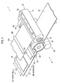
- Fig. 1 is a perspective view showing an intermittent cutting transferring device 1 according to the first embodiment.
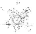
- Fig. 2 is a side view (view on arrow A of Fig. 1 ) showing the intermittent cutting transferring device 1 according to the first embodiment.
- the intermittent cutting transferring device 1 is configured to intermittently transfer a cut film sheet 10, obtained by cutting a continuum of cut film sheet 10A printed with patterns such as characters and figures, to a web 20 being fed continuously.
- a length (L1) of the cut film sheet 10 in its moving direction (hereinafter called the "MD direction") is shorter than a length (L2) thereof in a direction crossing the MD direction (this direction is hereinafter called the "CD direction").
- the intermittent cutting transferring device 1 is configured briefly of an upper blade roll 30, a lower blade roll 40, and a transfer roll 50.
- Two blades 32 are provided on an outer peripheral surface 31 of the upper blade roll 30.
- the upper blade roll 30 rotates at a peripheral velocity (V 1 ) approximately equal to a peripheral velocity of the lower blade roll 40.
- the upper blade roll 30 rotates at the peripheral velocity (V 1 ) higher than a velocity (V 2 ) in which the continuum of film sheet 10A is fed to the lower blade roll 40 by a pair of driving rolls 60 and 61.
- the upper blade roll 30 rotates at the peripheral velocity (V 1 ) approximately equal to a feeding velocity (V 3 ) of the web 20 continuously fed by driving rolls 62 and 63, or rotates at the peripheral velocity (V 1 ) lower than the feeding velocity (V 3 ) of the web 20.
- the lower blade roll 40 rotates at the peripheral velocity (V 1 ) approximately equal to the peripheral velocity of the upper blade roll 30, in a direction opposite to the direction in which the upper blade roll 30 rotates.
- V 1 peripheral velocity
- the configuration of the lower blade roll 40 will be described later (see Fig. 3 ).
- the transfer roll 50 brings the web 20 continuously fed by the driving rolls 62 and 63 into contact with the lower blade roll 40.
- the transfer roll 50 rotates at a peripheral velocity (V 4 ) approximately equal to the feeding velocity (V 3 ) of the web 20.
- the transfer roll 50 rotates at the peripheral velocity (V 4 ) approximately equal to the peripheral velocity (V 1 ) of the upper blade roll 30 and the lower blade roll 40 described above, or rotates at the peripheral velocity (V 4 ) higher than the peripheral velocity (V 1 ) of the upper blade roll 30 and the lower blade roll 40.
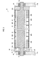
- Fig. 3 is a roll width direction sectional view (sectional view along B-B of Fig. 2 ) showing the lower blade roll 40 according to the first embodiment.
- the lower blade roll 40 is formed integrally with a roll shaft 70.
- the lower blade roll 40 is configured to be rotated between a pair of frames 71 A and 71 B by shaft bearings 72.
- Formed in the lower blade roll 40 are horizontal holes 45A and 45B penetrating from one end surface 44a to the other end surface 44b of the lower blade roll 40 and opening holes 46A and 46B connecting the horizontal holes 45A and 45B and suction holes 43.
- the suction holes 43 are formed at positions corresponding to the opening holes 46A and 46B.
- a suction member 80 is provided between the lower blade roll 40 and the one frame 71A, whereas a sealing member 90 is provided between the lower blade roll 40 and the other frame 71 B.
- the suction member 80 and the sealing member 90 each have a diameter approximately equal to the diameter of the lower blade roll 40, and are formed in a disk shape.
- the suction member 80 and the sealing member 90 are fixed to the frames 71A and 71 B, respectively, and are configured so as not to rotate together with the lower blade roll 40.
- the suction member 80 is provided with a first suction groove 81 which sucks the continuous film sheet 10A, a second suction groove 82 which sucks the cut film sheet 10 to guide the cut film sheet 10 to the web 20, and a transfer groove 83 for transferring, on the web 20, the cut film sheet 10 sucked onto the outer peripheral surface 41 of the lower blade roll 40.
- the first suction groove 81 is formed at a position corresponding to the horizontal hole 45A formed in the lower blade roll 40, and also to a portion of the outer peripheral surface 41 of the lower blade roll 40 around which the continuum of film sheet 10A is wound.
- the first suction groove 81 is connected with a suction connection pipe 84 connecting the first suction groove 81 and suction air supply means (not shown) which sucks air in the horizontal hole 45A.
- the second suction groove 82 is formed at a position corresponding to the horizontal hole 45B formed in the lower blade roll 40, and to a portion of the outer peripheral surface 41 of the lower blade roll 40 around which the cut film sheet 10 is wound.
- the second suction groove 82 is connected with a suction connection pipe 85 connecting the second suction groove 82 and suction air supply means (not shown) which sucks air in the horizontal hole 45B.
- the transfer groove 83 is formed at a position corresponding to the horizontal hole 45B formed in the lower blade roll 40, and to a portion to which the cut film sheet 10 is transferred.
- the transfer groove 83 is connected with a transfer connection pipe (not shown) connecting the transfer groove 83 and air releasing means (not shown) which releases the suction of air performed by the suction air supply means.
- the air releasing means does not necessarily need to release the suction of air performed by the suction air supply means, and may be configured to blow out air through the transfer groove 83 (transfer connection pipe).
- the suction member 80 is provided between the lower blade roll 40 and the one frame 71A.
- the suction member 80 may be additionally provided, instead of the sealing member 90, between the lower blade roll 40 and the other frame 71 B. That is, the suction air supply means may perform supply of air from both end sections of the horizontal holes 45A and 45B.
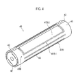
- Fig. 4 is a perspective view showing the lower blade roll 40 according to the first embodiment.
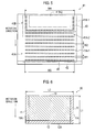
- Fig. 5 is a development view of the lower blade roll 40 according to the first embodiment.
- Fig. 6 is an upper view showing the cut film sheet according to the first embodiment.
- the suction holes 43 are formed in a first region 41A and in a second region 41 B on the outer peripheral surface 41 of the lower blade roll 40.
- the suction holes 43 are arranged at predetermined intervals in the roll peripheral direction and in the roll width direction, and are aligned such that the suction holes 43 that are adjacent in the roll peripheral direction are displaced from each other in the roll width direction (a so-called staggered alignment).
- the first region 41A is configured of suction regions 41A-1 each of which having the multiple suction holes 43 formed therein, and non-suction regions 41A-2 each of which having no suction hole 43 formed therein. Accordingly, the suction holding force in the suction regions 41A-1 is stronger than the suction holding force in the non-suction regions 41 A-2.
- the suction regions 41A-1 and the non-suction regions 41A-2 are provided in the roll width direction.
- the suction regions 41A-1 and the non-suction regions 41A-2 are provided alternately in the roll peripheral direction.
- Each of the regions 41A-1 is configured so that a width (W1) of the suction region 41A-1 in the roll peripheral direction can be shorter than a width (W2) of each non-suction region 41A-2 in the roll peripheral direction.
- Each of the regions 41A-1 is configured so that a width (W3) of the suction region 41A-1 in the roll width direction can be wider than the length (L2) of the cut film sheet 10 in the CD direction.
- the second region 41 B is configured of an edge area 41 B-1 having the multiple suction holes 43 formed therein, and a center area 41 B-2 having no suction hole 43 formed therein. Accordingly, the suction holding force in the edge area 41 B-1 is stronger than the suction holding force in the center area 41 B-2.
- the edge area 41 B-1 faces both side edge regions 11 and a front end region 12 formed ahead in the proceeding direction of the cut film sheet 10.
- the both side edge regions 11 of the cut film sheet 10 show regions within 25% of the length (L2) in the CD direction with both end sections 11A of the cut film sheet 10 as the references.
- the front end region 12 of the cut film sheet 10 formed ahead in the proceeding direction shows a region within 50% of the length (L1) in the MD direction with a front end section 12A of the cut film sheet as the reference.
- the area of the center area 41 B-2 needs to have an area that is 50% or more of a whole area of the cut film sheet 10.
- a maximum width (W4) of the edge area 41 B-1 in the roll width direction is approximately equivalent to the width (W3) of the suction region 41A-1 in the roll width direction described above, i.e., configured to be wider than the length (L2) of the cut film sheet 10 in the CD direction.
- the center area 41 B-2 faces a remaining region 13 which is a region other than the both side edge regions 11 and the front end region 12 formed ahead in the proceeding direction of the cut film sheet 10. Note that, as shown in Fig. 6 , the remaining region 13 shows a region inside the both side edge regions 11 and the front end region 12 formed ahead in the proceeding direction of the cut film sheet 10 described above.
- the intermittent cutting transferring device 1 guides the continuum of film sheet 10A between the blade 32 and the stationary blade 42 with the continuum of film sheet 10A being sucked onto the outer peripheral surface 41 of the lower blade roll 40 by the suction of the suction air supply means through the suction holes 43 formed in the first region 41A (suction region 41A-1) on the outer peripheral surface 41 of the lower blade roll 40.
- the continuum of film sheet 10A slides on the outer peripheral surface 41 of the lower blade roll 40 to be guided between the blade 32 and the stationary blade 42 because the upper blade roll 30 and the lower blade roll 40 rotate at the peripheral velocity (V 1 ) higher than the velocity (V 2 ) in which the continuum of film sheet 10A is fed to the lower blade roll 40.
- the intermittent cutting transferring device 1 intermittently cuts the continuum of film sheet 10A by bringing the blade 32 and the stationary blade 42 into contact with each other.
- the cut film sheet 10 is thus formed. Note that the length (L1) of the cut film sheet 10 in the MD direction is shorter than the length (L2) of the cut film sheet 10 in the CD direction.
- the intermittent cutting transferring device 1 guides the cut film sheet 10 to the web 20 while the cut film sheet 10 is being sucked onto the outer peripheral surface 41 of the lower blade roll 40 by the suction of the suction air supply means, through the suction holes 43 formed in the second region 41 B (edge area 41 B-1) on the outer peripheral surface 41 of the lower blade roll 40.
- the cut film sheet 10 is sucked onto the outer peripheral surface 41 of the lower blade roll 40 with the both side edge regions 11 and the front end region 12 formed ahead in the moving direction facing the edge area 41 B-1 of the second region 41 B as well as the remaining region 13 facing the center area 41 B-2 of the second region 41 B.
- the intermittent cutting transferring device 1 transfers the cut film sheet 10 sucked onto the outer side surface 41 of the lower blade roll 40 to the web 20 by releasing the suction of air performed by the suction air supply means.
- the suction holding force of the edge area 41B-1 is stronger than the suction holding force in the center area 41 B-2.
- the cut film sheet 10 comes into the suction holes 43 in less cases compared to the both side edge regions 11 and the front end region 12, whereby the formation of a wrinkle of the cut film sheet 10 can be suppressed. Moreover, the cut film sheet 10 is pulled toward the edge area 41 B-1 sides. Accordingly, even when the wrinkle is formed in the cut film sheet 10, the wrinkle formed in the cut film sheet 10 can be smoothed out in the remaining region 13 other than the both side edge regions 11 and the front end region 12.
- the air releasing means releases the suction of air performed by the suction air supply means, whereby the cut film sheet 10 makes contact on the web 20 firstly with the center area 41 B-2 having a weak suction holding force. That is, since the suction holding force in the center area 41 B-2 is weaker than the suction holding force in the edge area 41 B-1, it becomes easier to transfer the cut film sheet 10 to the web 20 from the center area 41B-2 having a weak suction holding force, as compared to the case where the suction holding force is the same in the entire region of the outer peripheral surface 41 of the lower blade roll 40. Thus, the formation of a wrinkle in the cut film sheet 10 can be suppressed.
- the intermittent cutting transferring device 1 has no suction hole 43 formed in the center area 41 B-2. Accordingly, at the time of the film feeding and the film transfer, the cut film sheet 10 is not sucked onto the outer peripheral surface 41 of the lower blade roll 40 in the center area 41 B-2, whereby the cut film sheet 10 does not come into the suction hole 43. Thus, the formation of a wrinkle in the cut film sheet 10 can be suppressed.
- the suction holding force in the edge area 41 B-1 is stronger than the suction holding force in the center area 41 B-2. Accordingly, the formation of a wrinkle in the cut film sheet 10 can be suppressed. Even when the wrinkle is formed in the cut film sheet 10, a wrinkle formed in the cut film sheet 10 can be smoothed out. Thus, it is particularly effective when the length (L1) of the cut film sheet 10 in the MD direction is shorter than the length (L2) in the CD direction.
- the intermittent cutting transferring device 1 is configured so that the maximum width (W4) of the edge area 41B-1 in the roll width direction is approximately equal to the width (W3) of the suction region 41A-1 in the roll width direction described above, or, in other words, so that the maximum width (W4) is wider than the length (L2) of the cut film sheet 10 in the CD direction. Accordingly, the both side edge regions 11 and the front end region 12 formed ahead in the proceeding direction of the cut film sheet 10 can reliably be sucked by the suction through the suction holes 43 formed in the edge area 41 B-1. Thus, at the time of transfer, the both side edge regions 11 and the front end region 12 formed ahead in the proceeding direction of the cut film sheet 10 can be prevented from being bent.
- the configuration of the intermittent cutting transferring device 1 according to a second embodiment will be described with reference to the drawings. Note that the same portions as those of the above-described intermittent cutting transferring device 1 according to the first embodiment are denoted by the same reference numerals, and differing portions will mainly be described.
- the first embodiment described above has no suction hole 43 formed in the center area 41 B-2.
- the suction holes 43 are formed in the center area 41 B-2.
- Fig. 7 is a roll width direction sectional view showing the lower blade roll 40 according to the second embodiment.
- the intermittent cutting transferring device 1 is configured so that at least one of the suction holding force in the edge area 41B-1 and the suction holding force in the center area 41 B-2 would be variable.
- the suction member 80 is provided also between the lower blade roll 40 and the other frame 71 B.
- a first horizontal hole 450A and a first opening hole 460A are formed in the lower blade roll 40.
- the first horizontal hole 450A penetrates from the one end surface 44a to the other end surface 44b of the lower blade roll 40, and the first opening hole 460A connects the first horizontal hole 450A and the suction holes 43 formed in the edge area 41 B-1.
- a second horizontal hole 450B and a second opening hole 460B are also formed in the lower blade roll 40.
- the second horizontal hole 450B extends approximately in parallel to the first horizontal hole 450A and penetrates from the one end surface 44a to the other end surface 44b of the lower blade roll 40, and the second opening hole 460B connects the second horizontal hole 450B and the suction holes 43 formed in the center area 41 B-2.
- the first horizontal hole 450A is connected to suction air supply means (not shown) through a first suction groove 81 A and a suction connection pipe 84A.
- the second horizontal hole 450B is connected to suction air supply means (not shown), which is provided separately from the suction air supply means connected with the first horizontal hole 450A, through a first suction groove 81B and a suction connection pipe 84B.
- a third horizontal hole 451A and a third opening hole 461A are provided in the lower blade roll 40.
- the third horizontal hole 451A penetrates from the one end surface 44a to the other end surface 44b of the lower blade roll 40, and the third opening hole 461A connects the third horizontal hole 451 A and the suction holes 43 formed in the edge area 41 B-1.
- a fourth horizontal hole 451 B and a fourth opening hole 461 B are also formed in the lower blade roll 40.
- the fourth horizontal hole 451 B extends approximately in parallel to the third horizontal hole 451A and penetrates from the one end surface 44a to the other end surface 44b of the lower blade roll 40, and the fourth opening hole 461 B connects the fourth horizontal hole 451 B and the suction holes 43 formed in the center area 41B-2.
- the third horizontal hole 451A is connected to suction air supply means (not shown) through a second suction groove 82A and a suction connection pipe 85A.
- the fourth horizontal hole 451 B is connected to suction air supply means (not shown), which is provided separately from the suction air supply means connected with the third horizontal hole 451A, through a second suction groove 82B and a suction connection pipe 85B.
- FIG. 8 is a development view showing the lower blade roll 40 according to the second embodiment.
- the suction holes 43 are formed in the entire region of the second region 41 B. Note that the suction holding force in the edge area 41B-1 is stronger than the suction holding force in the center area 41B-2.
- the suction holding force in the edge area 41 B-1 can be made stronger than the suction holding force in the center area 41 B-2.
- the suction force of the suction air supply means through the suction holes 43 in the edge area 41 B-1 is stronger than the suction force of the suction air supply means through the suction holes 43 formed in the center area 41 B-2.
- the aperture ratio of the suction holes 43 formed in the edge area 41 B-1 may be larger than the aperture ratio of the suction holes 43 formed in the center area 41 B-2.
- the edge area 41 B-1 and the center area 41 B-2 can be set in accordance with the size of the cut film sheet 10 (for example, the length (L2) of the cut film sheet 10 in the CD direction). Accordingly, the intermittent cutting transferring device 1 according to the second embodiment is able to manufacture the cut film sheet 10 in various sizes.
- two blades 32 are provided on the outer peripheral surface 31 of the upper blade roll 30.
- at least one blade 32 may be provided.
- at least one stationary blade 42 may be provided on the outer peripheral surface 41 of the lower blade roll 40.
- the first region 41A is configured of the suction region 41A-1 and the non-suction region 41A-2, but it is not limited thereto. It is needless to say that the suction holes 43 may be formed in the entire region.
- the present invention is useful in manufacturing method for an absorptive article since it is possible to provide an intermittent cutting transferring device, which can suppress the formation of a wrinkle in a film sheet and which can smooth out a wrinkle formed in the film sheet even when the wrinkle is formed in the film sheet.
Landscapes
- Engineering & Computer Science (AREA)
- Health & Medical Sciences (AREA)
- Life Sciences & Earth Sciences (AREA)
- Mechanical Engineering (AREA)
- Epidemiology (AREA)
- Public Health (AREA)
- Heart & Thoracic Surgery (AREA)
- Vascular Medicine (AREA)
- Manufacturing & Machinery (AREA)
- Animal Behavior & Ethology (AREA)
- General Health & Medical Sciences (AREA)
- Biomedical Technology (AREA)
- Veterinary Medicine (AREA)
- Forests & Forestry (AREA)
- Absorbent Articles And Supports Therefor (AREA)
- Perforating, Stamping-Out Or Severing By Means Other Than Cutting (AREA)
- Advancing Webs (AREA)
- Labeling Devices (AREA)
- Auxiliary Devices For And Details Of Packaging Control (AREA)
Applications Claiming Priority (2)
| Application Number | Priority Date | Filing Date | Title |
|---|---|---|---|
| JP2008171894A JP5123760B2 (ja) | 2008-06-30 | 2008-06-30 | 間欠切断転写装置 |
| PCT/JP2009/061920 WO2010001881A1 (fr) | 2008-06-30 | 2009-06-30 | Dispositif de découpe et de transfert fonctionnant par intermittence |
Publications (3)
| Publication Number | Publication Date |
|---|---|
| EP2301875A1 true EP2301875A1 (fr) | 2011-03-30 |
| EP2301875A4 EP2301875A4 (fr) | 2011-10-05 |
| EP2301875B1 EP2301875B1 (fr) | 2013-07-03 |
Family
ID=41445992
Family Applications (1)
| Application Number | Title | Priority Date | Filing Date |
|---|---|---|---|
| EP20090773459 Not-in-force EP2301875B1 (fr) | 2008-06-30 | 2009-06-30 | Dispositif de découpe et de transfert fonctionnant par intermittence |
Country Status (8)
| Country | Link |
|---|---|
| US (2) | US8276638B2 (fr) |
| EP (1) | EP2301875B1 (fr) |
| JP (1) | JP5123760B2 (fr) |
| CN (1) | CN102076585B (fr) |
| AR (1) | AR072417A1 (fr) |
| RU (1) | RU2402479C2 (fr) |
| TW (1) | TW201008860A (fr) |
| WO (1) | WO2010001881A1 (fr) |
Cited By (1)
| Publication number | Priority date | Publication date | Assignee | Title |
|---|---|---|---|---|
| EP2374437A4 (fr) * | 2008-12-18 | 2013-05-01 | Uni Charm Corp | Procédé et dispositif de fabrication d'un élément composite constitué de feuillets et conçu pour être utilisé dans un article absorbant |
Families Citing this family (22)
| Publication number | Priority date | Publication date | Assignee | Title |
|---|---|---|---|---|
| US9944487B2 (en) | 2007-02-21 | 2018-04-17 | Curt G. Joa, Inc. | Single transfer insert placement method and apparatus |
| US9550306B2 (en) | 2007-02-21 | 2017-01-24 | Curt G. Joa, Inc. | Single transfer insert placement and apparatus with cross-direction insert placement control |
| JP5123760B2 (ja) | 2008-06-30 | 2013-01-23 | ユニ・チャーム株式会社 | 間欠切断転写装置 |
| WO2011012926A1 (fr) * | 2009-07-29 | 2011-02-03 | Sidel S.P.A. | Unité de coupe pour machines d'étiquetage |
| US9902083B2 (en) | 2010-09-30 | 2018-02-27 | The Procter & Gamble Company | Absorbent article substrate trim material removal process and apparatus |
| EP2945871A1 (fr) * | 2012-12-10 | 2015-11-25 | G. Mondini SpA | Machine de fermeture hermétique sans résidus de film |
| US8939445B2 (en) * | 2013-05-30 | 2015-01-27 | Kimberly-Clark Worldwide, Inc. | Vacuum roll with internal rotary valve |
| CN104720982B (zh) * | 2015-02-27 | 2018-10-26 | 安庆市恒昌机械制造有限责任公司 | 卫生用品生产线上片状材料切断、转移、复合方法 |
| US20170341256A1 (en) * | 2016-05-24 | 2017-11-30 | The Procter & Gamble Company | Rotary Anvil |
| JP6829814B2 (ja) * | 2017-03-13 | 2021-02-17 | 日本電気硝子株式会社 | ガラスフィルムの製造方法 |
| JP6976074B2 (ja) * | 2017-04-26 | 2021-12-01 | 住友化学株式会社 | 搬送装置および積層体の製造方法 |
| US10820499B2 (en) * | 2018-06-08 | 2020-11-03 | Cnh Industrial America Llc | Hybrid disc cutting system having a knife mount for an agricultural vehicle |
| CN109051974B (zh) * | 2018-07-05 | 2023-10-31 | 山东钢铁股份有限公司 | 一种随动式薄膜在线铺设切割装置 |
| CN109550633A (zh) * | 2018-12-17 | 2019-04-02 | 安徽迈德普斯医疗科技有限公司 | 一种给手术单覆胶装置 |
| CN115151486B (zh) * | 2019-12-05 | 2024-01-23 | 西得乐公司 | 用于从标签材料卷材切割标签的切割装置 |
| JP7736457B2 (ja) * | 2021-05-31 | 2025-09-09 | 株式会社ディスコ | シート貼着装置 |
| CN113633468A (zh) * | 2021-08-11 | 2021-11-12 | 中山佳健生活用品有限公司 | 一种卫生巾芯体在线加工渗透间隙的工艺方法 |
| CN113712736A (zh) * | 2021-08-30 | 2021-11-30 | 福建恒安集团有限公司 | 一种可变吸附宽度的导流层短切刀机构 |
| CN114248530B (zh) * | 2021-12-30 | 2024-01-12 | 保定盛通建材科技开发有限公司 | 镀铝锌板用覆膜机 |
| US11618177B1 (en) | 2022-04-12 | 2023-04-04 | Bradley W Boesel | Orbital knife |
| IT202200013189A1 (it) * | 2022-06-22 | 2023-12-22 | Fameccanica Data Spa | Procedimento per il taglio trasversale di un nastro idrosolubile |
| CN115418848B (zh) * | 2022-09-23 | 2024-02-13 | 绍兴博利豪家纺有限公司 | 一种高效裁布机 |
Family Cites Families (21)
| Publication number | Priority date | Publication date | Assignee | Title |
|---|---|---|---|---|
| SU42023A1 (ru) * | 1933-11-02 | 1935-03-31 | А.В. Терещенко | Станок дл вырезки деталей из ткани, резины и т.п. |
| US4016032A (en) * | 1972-11-30 | 1977-04-05 | Valmet Oy | Suction roll for transferring a web away from a press section |
| JPS5162847U (fr) * | 1974-11-12 | 1976-05-18 | ||
| JPS59112010A (ja) | 1982-12-15 | 1984-06-28 | ユニ・チャ−ム株式会社 | 使い捨て衛生物品に弾性部材を取り付ける方法 |
| SU1743890A1 (ru) * | 1988-12-12 | 1992-06-30 | Предприятие П/Я В-8996 | Устройство дл резки тонколистного рулонного материала |
| JP2709168B2 (ja) * | 1989-12-25 | 1998-02-04 | 株式会社ナべヤ | コールドストリップ用蛇行防止ロール |
| US5137758A (en) * | 1991-03-27 | 1992-08-11 | Minnesota Mining And Manufacturing Company | Apparatus and method for coating flexible sheets while inhibiting curl |
| RU2013199C1 (ru) * | 1991-08-02 | 1994-05-30 | Акционерное общество "Белокалитвинское металлургическое производственное объединение" | Устройство для поперечной резки полотна на мерные длины |
| US5405487A (en) * | 1992-06-30 | 1995-04-11 | Cms Gilbreth Packaging Systems, Inc. | Apparatus and method for applying labels onto small cylindrical articles and web and adhesive delivery mechanism |
| CH688893A5 (de) * | 1994-05-11 | 1998-05-15 | De La Rue Giori Sa | Zugwalze zum Transport einer Materialbahn, insbesondere einer Papierbahn in einer Rollendruckmaschine. |
| JP3695875B2 (ja) | 1997-02-04 | 2005-09-14 | 花王株式会社 | 貼付シートの間欠切断転写装置 |
| CA2264689A1 (fr) | 1997-03-19 | 1998-09-24 | The Procter & Gamble Company | Procede d'assemblage de materiaux en bande ou en film utilisant une charge electrostatique |
| JP2000177897A (ja) * | 1998-12-16 | 2000-06-27 | Toray Ind Inc | サクションロールならびにフイルムの搬送装置 |
| US6634269B2 (en) * | 2001-03-15 | 2003-10-21 | The Procter & Gamble Company | Apparatus and method for associating cut sheet sections with a moving carrier web |
| US6811019B2 (en) * | 2001-06-29 | 2004-11-02 | The Procter & Gamble Company | Method and apparatus utilizing servo motors for placing parts onto a moving web |
| EP1743069A1 (fr) * | 2004-05-07 | 2007-01-17 | Voith Patent GmbH | Cylindre aspirant de machine pour produire une bande de matiere fibreuse |
| US7533709B2 (en) * | 2005-05-31 | 2009-05-19 | Curt G. Joa, Inc. | High speed vacuum porting |
| US7618513B2 (en) * | 2005-05-31 | 2009-11-17 | Curt G. Joa, Inc. | Web stabilization on a slip and cut applicator |
| JP4726674B2 (ja) * | 2006-03-29 | 2011-07-20 | 花王株式会社 | シート切断方法及び装置 |
| JP5022042B2 (ja) | 2007-01-09 | 2012-09-12 | 欣興電子股▲分▼有限公司 | 半導体素子埋め込み支持基板の積層構造とその製造方法 |
| JP5123760B2 (ja) | 2008-06-30 | 2013-01-23 | ユニ・チャーム株式会社 | 間欠切断転写装置 |
-
2008
- 2008-06-30 JP JP2008171894A patent/JP5123760B2/ja not_active Expired - Fee Related
- 2008-08-22 RU RU2008134332A patent/RU2402479C2/ru active
-
2009
- 2009-02-20 US US12/390,099 patent/US8276638B2/en not_active Expired - Fee Related
- 2009-06-29 TW TW98121824A patent/TW201008860A/zh unknown
- 2009-06-30 WO PCT/JP2009/061920 patent/WO2010001881A1/fr not_active Ceased
- 2009-06-30 AR ARP090102431 patent/AR072417A1/es not_active Application Discontinuation
- 2009-06-30 CN CN2009801250196A patent/CN102076585B/zh not_active Expired - Fee Related
- 2009-06-30 EP EP20090773459 patent/EP2301875B1/fr not_active Not-in-force
-
2012
- 2012-08-30 US US13/598,726 patent/US8789572B2/en not_active Expired - Fee Related
Cited By (2)
| Publication number | Priority date | Publication date | Assignee | Title |
|---|---|---|---|---|
| EP2374437A4 (fr) * | 2008-12-18 | 2013-05-01 | Uni Charm Corp | Procédé et dispositif de fabrication d'un élément composite constitué de feuillets et conçu pour être utilisé dans un article absorbant |
| US9248053B2 (en) | 2008-12-18 | 2016-02-02 | Unicharm Corporation | Manufacturing method and manufacturing equipment of composite body of sheet-like member of absorbent article |
Also Published As
| Publication number | Publication date |
|---|---|
| US20120318111A1 (en) | 2012-12-20 |
| EP2301875B1 (fr) | 2013-07-03 |
| AR072417A1 (es) | 2010-08-25 |
| US8789572B2 (en) | 2014-07-29 |
| TW201008860A (en) | 2010-03-01 |
| CN102076585B (zh) | 2013-11-06 |
| US20090321021A1 (en) | 2009-12-31 |
| JP2010013195A (ja) | 2010-01-21 |
| RU2008134332A (ru) | 2010-02-27 |
| US8276638B2 (en) | 2012-10-02 |
| JP5123760B2 (ja) | 2013-01-23 |
| EP2301875A4 (fr) | 2011-10-05 |
| RU2402479C2 (ru) | 2010-10-27 |
| CN102076585A (zh) | 2011-05-25 |
| WO2010001881A1 (fr) | 2010-01-07 |
Similar Documents
| Publication | Publication Date | Title |
|---|---|---|
| EP2301875B1 (fr) | Dispositif de découpe et de transfert fonctionnant par intermittence | |
| EP2301876B1 (fr) | Dispositif de découpe et de transfert fonctionnant par intermittence | |
| WO2010051146A4 (fr) | Bouchon refermable à découpe bilatérale doté d'un adhésif sensible à la pression et procédé de fabrication associé | |
| JP2006187817A (ja) | ギロチンカッタおよびテープ貼付け装置 | |
| KR20120086708A (ko) | 주름형 에지 닙 | |
| JP4524252B2 (ja) | 着用物品の製造方法 | |
| JP6220795B2 (ja) | 吸収性物品に係る連続シートの複合体の製造方法、及び製造装置 | |
| JPH11286357A (ja) | 巻取紙のほぐれ止め用タブシール及びタブシール連続体 | |
| JP2008296320A (ja) | ラベル連続体の生産装置 | |
| JP3106008U (ja) | 粘着テープ | |
| JP2009220964A (ja) | ウェブ搬送装置およびウェブ接続方法 | |
| JP2012153065A (ja) | シート製造装置および製造方法 | |
| JP3785112B2 (ja) | 折り曲げ用ミシン目入りのプラスチックシート | |
| KR20250139980A (ko) | 전극시트 절단장치 | |
| JP5832720B2 (ja) | ラップフィルム用カートン | |
| JPH11235759A (ja) | フィルム吸着装置 | |
| JP2003155150A (ja) | 巻取紙補助タブ及び巻取紙補助タブテープ並びに巻取紙 | |
| HK1140741B (en) | A method and a unit for producing stamps applied to cigarette packets |
Legal Events
| Date | Code | Title | Description |
|---|---|---|---|
| PUAI | Public reference made under article 153(3) epc to a published international application that has entered the european phase |
Free format text: ORIGINAL CODE: 0009012 |
|
| 17P | Request for examination filed |
Effective date: 20110124 |
|
| AK | Designated contracting states |
Kind code of ref document: A1 Designated state(s): AT BE BG CH CY CZ DE DK EE ES FI FR GB GR HR HU IE IS IT LI LT LU LV MC MK MT NL NO PL PT RO SE SI SK TR |
|
| AX | Request for extension of the european patent |
Extension state: AL BA RS |
|
| RIN1 | Information on inventor provided before grant (corrected) |
Inventor name: YAMAMOTO, HIROKI |
|
| A4 | Supplementary search report drawn up and despatched |
Effective date: 20110906 |
|
| DAX | Request for extension of the european patent (deleted) | ||
| RIC1 | Information provided on ipc code assigned before grant |
Ipc: B65H 20/12 20060101ALI20110831BHEP Ipc: B65H 27/00 20060101ALI20110831BHEP Ipc: B65H 37/04 20060101AFI20110831BHEP Ipc: A61F 13/15 20060101ALI20110831BHEP Ipc: B65H 35/08 20060101ALI20110831BHEP Ipc: A61F 13/49 20060101ALI20110831BHEP |
|
| GRAP | Despatch of communication of intention to grant a patent |
Free format text: ORIGINAL CODE: EPIDOSNIGR1 |
|
| GRAS | Grant fee paid |
Free format text: ORIGINAL CODE: EPIDOSNIGR3 |
|
| GRAA | (expected) grant |
Free format text: ORIGINAL CODE: 0009210 |
|
| AK | Designated contracting states |
Kind code of ref document: B1 Designated state(s): AT BE BG CH CY CZ DE DK EE ES FI FR GB GR HR HU IE IS IT LI LT LU LV MC MK MT NL NO PL PT RO SE SI SK TR |
|
| REG | Reference to a national code |
Ref country code: GB Ref legal event code: FG4D |
|
| REG | Reference to a national code |
Ref country code: CH Ref legal event code: EP Ref country code: AT Ref legal event code: REF Ref document number: 619615 Country of ref document: AT Kind code of ref document: T Effective date: 20130715 |
|
| RAP2 | Party data changed (patent owner data changed or rights of a patent transferred) |
Owner name: UNICHARM CORPORATION |
|
| REG | Reference to a national code |
Ref country code: IE Ref legal event code: FG4D |
|
| REG | Reference to a national code |
Ref country code: DE Ref legal event code: R096 Ref document number: 602009016904 Country of ref document: DE Effective date: 20130829 |
|
| REG | Reference to a national code |
Ref country code: SE Ref legal event code: TRGR |
|
| REG | Reference to a national code |
Ref country code: NL Ref legal event code: T3 |
|
| PG25 | Lapsed in a contracting state [announced via postgrant information from national office to epo] |
Ref country code: SI Free format text: LAPSE BECAUSE OF FAILURE TO SUBMIT A TRANSLATION OF THE DESCRIPTION OR TO PAY THE FEE WITHIN THE PRESCRIBED TIME-LIMIT Effective date: 20130703 |
|
| REG | Reference to a national code |
Ref country code: AT Ref legal event code: MK05 Ref document number: 619615 Country of ref document: AT Kind code of ref document: T Effective date: 20130703 |
|
| REG | Reference to a national code |
Ref country code: LT Ref legal event code: MG4D |
|
| PG25 | Lapsed in a contracting state [announced via postgrant information from national office to epo] |
Ref country code: LT Free format text: LAPSE BECAUSE OF FAILURE TO SUBMIT A TRANSLATION OF THE DESCRIPTION OR TO PAY THE FEE WITHIN THE PRESCRIBED TIME-LIMIT Effective date: 20130703 Ref country code: NO Free format text: LAPSE BECAUSE OF FAILURE TO SUBMIT A TRANSLATION OF THE DESCRIPTION OR TO PAY THE FEE WITHIN THE PRESCRIBED TIME-LIMIT Effective date: 20131003 Ref country code: IS Free format text: LAPSE BECAUSE OF FAILURE TO SUBMIT A TRANSLATION OF THE DESCRIPTION OR TO PAY THE FEE WITHIN THE PRESCRIBED TIME-LIMIT Effective date: 20131103 Ref country code: CY Free format text: LAPSE BECAUSE OF FAILURE TO SUBMIT A TRANSLATION OF THE DESCRIPTION OR TO PAY THE FEE WITHIN THE PRESCRIBED TIME-LIMIT Effective date: 20130710 Ref country code: HR Free format text: LAPSE BECAUSE OF FAILURE TO SUBMIT A TRANSLATION OF THE DESCRIPTION OR TO PAY THE FEE WITHIN THE PRESCRIBED TIME-LIMIT Effective date: 20130703 Ref country code: PT Free format text: LAPSE BECAUSE OF FAILURE TO SUBMIT A TRANSLATION OF THE DESCRIPTION OR TO PAY THE FEE WITHIN THE PRESCRIBED TIME-LIMIT Effective date: 20131104 Ref country code: BE Free format text: LAPSE BECAUSE OF FAILURE TO SUBMIT A TRANSLATION OF THE DESCRIPTION OR TO PAY THE FEE WITHIN THE PRESCRIBED TIME-LIMIT Effective date: 20130703 Ref country code: AT Free format text: LAPSE BECAUSE OF FAILURE TO SUBMIT A TRANSLATION OF THE DESCRIPTION OR TO PAY THE FEE WITHIN THE PRESCRIBED TIME-LIMIT Effective date: 20130703 |
|
| PG25 | Lapsed in a contracting state [announced via postgrant information from national office to epo] |
Ref country code: LV Free format text: LAPSE BECAUSE OF FAILURE TO SUBMIT A TRANSLATION OF THE DESCRIPTION OR TO PAY THE FEE WITHIN THE PRESCRIBED TIME-LIMIT Effective date: 20130703 Ref country code: ES Free format text: LAPSE BECAUSE OF FAILURE TO SUBMIT A TRANSLATION OF THE DESCRIPTION OR TO PAY THE FEE WITHIN THE PRESCRIBED TIME-LIMIT Effective date: 20131014 Ref country code: PL Free format text: LAPSE BECAUSE OF FAILURE TO SUBMIT A TRANSLATION OF THE DESCRIPTION OR TO PAY THE FEE WITHIN THE PRESCRIBED TIME-LIMIT Effective date: 20130703 Ref country code: FI Free format text: LAPSE BECAUSE OF FAILURE TO SUBMIT A TRANSLATION OF THE DESCRIPTION OR TO PAY THE FEE WITHIN THE PRESCRIBED TIME-LIMIT Effective date: 20130703 Ref country code: GR Free format text: LAPSE BECAUSE OF FAILURE TO SUBMIT A TRANSLATION OF THE DESCRIPTION OR TO PAY THE FEE WITHIN THE PRESCRIBED TIME-LIMIT Effective date: 20131004 |
|
| PG25 | Lapsed in a contracting state [announced via postgrant information from national office to epo] |
Ref country code: CY Free format text: LAPSE BECAUSE OF FAILURE TO SUBMIT A TRANSLATION OF THE DESCRIPTION OR TO PAY THE FEE WITHIN THE PRESCRIBED TIME-LIMIT Effective date: 20130703 |
|
| PG25 | Lapsed in a contracting state [announced via postgrant information from national office to epo] |
Ref country code: CZ Free format text: LAPSE BECAUSE OF FAILURE TO SUBMIT A TRANSLATION OF THE DESCRIPTION OR TO PAY THE FEE WITHIN THE PRESCRIBED TIME-LIMIT Effective date: 20130703 Ref country code: RO Free format text: LAPSE BECAUSE OF FAILURE TO SUBMIT A TRANSLATION OF THE DESCRIPTION OR TO PAY THE FEE WITHIN THE PRESCRIBED TIME-LIMIT Effective date: 20130703 Ref country code: EE Free format text: LAPSE BECAUSE OF FAILURE TO SUBMIT A TRANSLATION OF THE DESCRIPTION OR TO PAY THE FEE WITHIN THE PRESCRIBED TIME-LIMIT Effective date: 20130703 Ref country code: DK Free format text: LAPSE BECAUSE OF FAILURE TO SUBMIT A TRANSLATION OF THE DESCRIPTION OR TO PAY THE FEE WITHIN THE PRESCRIBED TIME-LIMIT Effective date: 20130703 Ref country code: SK Free format text: LAPSE BECAUSE OF FAILURE TO SUBMIT A TRANSLATION OF THE DESCRIPTION OR TO PAY THE FEE WITHIN THE PRESCRIBED TIME-LIMIT Effective date: 20130703 |
|
| PLBE | No opposition filed within time limit |
Free format text: ORIGINAL CODE: 0009261 |
|
| STAA | Information on the status of an ep patent application or granted ep patent |
Free format text: STATUS: NO OPPOSITION FILED WITHIN TIME LIMIT |
|
| PG25 | Lapsed in a contracting state [announced via postgrant information from national office to epo] |
Ref country code: IT Free format text: LAPSE BECAUSE OF FAILURE TO SUBMIT A TRANSLATION OF THE DESCRIPTION OR TO PAY THE FEE WITHIN THE PRESCRIBED TIME-LIMIT Effective date: 20130703 |
|
| 26N | No opposition filed |
Effective date: 20140404 |
|
| REG | Reference to a national code |
Ref country code: DE Ref legal event code: R097 Ref document number: 602009016904 Country of ref document: DE Effective date: 20140404 |
|
| REG | Reference to a national code |
Ref country code: DE Ref legal event code: R119 Ref document number: 602009016904 Country of ref document: DE |
|
| REG | Reference to a national code |
Ref country code: NL Ref legal event code: V1 Effective date: 20150101 |
|
| PG25 | Lapsed in a contracting state [announced via postgrant information from national office to epo] |
Ref country code: LU Free format text: LAPSE BECAUSE OF FAILURE TO SUBMIT A TRANSLATION OF THE DESCRIPTION OR TO PAY THE FEE WITHIN THE PRESCRIBED TIME-LIMIT Effective date: 20140630 Ref country code: MC Free format text: LAPSE BECAUSE OF FAILURE TO SUBMIT A TRANSLATION OF THE DESCRIPTION OR TO PAY THE FEE WITHIN THE PRESCRIBED TIME-LIMIT Effective date: 20130703 |
|
| REG | Reference to a national code |
Ref country code: CH Ref legal event code: PL |
|
| GBPC | Gb: european patent ceased through non-payment of renewal fee |
Effective date: 20140630 |
|
| REG | Reference to a national code |
Ref country code: SE Ref legal event code: EUG |
|
| REG | Reference to a national code |
Ref country code: IE Ref legal event code: MM4A |
|
| REG | Reference to a national code |
Ref country code: DE Ref legal event code: R119 Ref document number: 602009016904 Country of ref document: DE Effective date: 20150101 |
|
| REG | Reference to a national code |
Ref country code: FR Ref legal event code: ST Effective date: 20150227 |
|
| PG25 | Lapsed in a contracting state [announced via postgrant information from national office to epo] |
Ref country code: NL Free format text: LAPSE BECAUSE OF NON-PAYMENT OF DUE FEES Effective date: 20150101 |
|
| PG25 | Lapsed in a contracting state [announced via postgrant information from national office to epo] |
Ref country code: DE Free format text: LAPSE BECAUSE OF NON-PAYMENT OF DUE FEES Effective date: 20150101 Ref country code: CH Free format text: LAPSE BECAUSE OF NON-PAYMENT OF DUE FEES Effective date: 20140630 Ref country code: LI Free format text: LAPSE BECAUSE OF NON-PAYMENT OF DUE FEES Effective date: 20140630 Ref country code: IE Free format text: LAPSE BECAUSE OF NON-PAYMENT OF DUE FEES Effective date: 20140630 |
|
| PG25 | Lapsed in a contracting state [announced via postgrant information from national office to epo] |
Ref country code: GB Free format text: LAPSE BECAUSE OF NON-PAYMENT OF DUE FEES Effective date: 20140630 Ref country code: FR Free format text: LAPSE BECAUSE OF NON-PAYMENT OF DUE FEES Effective date: 20140630 Ref country code: SE Free format text: LAPSE BECAUSE OF NON-PAYMENT OF DUE FEES Effective date: 20140701 |
|
| PG25 | Lapsed in a contracting state [announced via postgrant information from national office to epo] |
Ref country code: MT Free format text: LAPSE BECAUSE OF FAILURE TO SUBMIT A TRANSLATION OF THE DESCRIPTION OR TO PAY THE FEE WITHIN THE PRESCRIBED TIME-LIMIT Effective date: 20130703 |
|
| PG25 | Lapsed in a contracting state [announced via postgrant information from national office to epo] |
Ref country code: BG Free format text: LAPSE BECAUSE OF FAILURE TO SUBMIT A TRANSLATION OF THE DESCRIPTION OR TO PAY THE FEE WITHIN THE PRESCRIBED TIME-LIMIT Effective date: 20130703 |
|
| PG25 | Lapsed in a contracting state [announced via postgrant information from national office to epo] |
Ref country code: HU Free format text: LAPSE BECAUSE OF FAILURE TO SUBMIT A TRANSLATION OF THE DESCRIPTION OR TO PAY THE FEE WITHIN THE PRESCRIBED TIME-LIMIT; INVALID AB INITIO Effective date: 20090630 Ref country code: TR Free format text: LAPSE BECAUSE OF FAILURE TO SUBMIT A TRANSLATION OF THE DESCRIPTION OR TO PAY THE FEE WITHIN THE PRESCRIBED TIME-LIMIT Effective date: 20130703 |
|
| PG25 | Lapsed in a contracting state [announced via postgrant information from national office to epo] |
Ref country code: MK Free format text: LAPSE BECAUSE OF FAILURE TO SUBMIT A TRANSLATION OF THE DESCRIPTION OR TO PAY THE FEE WITHIN THE PRESCRIBED TIME-LIMIT Effective date: 20130703 |