EP2302147B1 - Système de gouttière métallique avec raccordement amélioré - Google Patents
Système de gouttière métallique avec raccordement amélioré Download PDFInfo
- Publication number
- EP2302147B1 EP2302147B1 EP10178104.5A EP10178104A EP2302147B1 EP 2302147 B1 EP2302147 B1 EP 2302147B1 EP 10178104 A EP10178104 A EP 10178104A EP 2302147 B1 EP2302147 B1 EP 2302147B1
- Authority
- EP
- European Patent Office
- Prior art keywords
- gutter
- metal
- strip
- sealant
- track
- Prior art date
- Legal status (The legal status is an assumption and is not a legal conclusion. Google has not performed a legal analysis and makes no representation as to the accuracy of the status listed.)
- Active
Links
Images


Classifications
-
- E—FIXED CONSTRUCTIONS
- E04—BUILDING
- E04D—ROOF COVERINGS; SKY-LIGHTS; GUTTERS; ROOF-WORKING TOOLS
- E04D13/00—Special arrangements or devices in connection with roof coverings; Protection against birds; Roof drainage ; Sky-lights
- E04D13/04—Roof drainage; Drainage fittings in flat roofs, balconies or the like
- E04D13/064—Gutters
- E04D13/068—Means for fastening gutter parts together
-
- E—FIXED CONSTRUCTIONS
- E04—BUILDING
- E04D—ROOF COVERINGS; SKY-LIGHTS; GUTTERS; ROOF-WORKING TOOLS
- E04D13/00—Special arrangements or devices in connection with roof coverings; Protection against birds; Roof drainage ; Sky-lights
- E04D13/04—Roof drainage; Drainage fittings in flat roofs, balconies or the like
- E04D13/064—Gutters
- E04D13/068—Means for fastening gutter parts together
- E04D13/0685—Means for fastening gutter parts together in combination with hanging means
Definitions
- the present invention relates to an improved metal gutter system.
- a metal gutter system incorporating a new gutter joint and a method of assembling the new gutter joint.
- Metal gutter systems are known. They have been used for many years on prestige housing, and public or tall buildings in preference to the equivalent plastic systems where the higher installation cost can be balanced favourably against the lower maintenance costs and longer product life.
- the rubber seals used in plastic guttering can harden with age and this, together with the plastic components becoming more brittle with time, can mean that the maximum life of a plastic gutter system is usually limited to 25 years before replacement is necessary.
- Metal gutters, by comparison, can be guaranteed for at least 50 years. The extra cost is easily justified by the savings in future maintenance costs.
- non-plastic gutter systems are necessary for all types of building in order to accommodate low temperatures where plastic components may become overly brittle.
- a metal gutter would be used but other materials are possible.
- a number of methods are already employed for joining together the metal gutter components of a metal gutter system. For example, it is known to join metal gutter components using fasteners such as bolts or rivets extending through an overlapped region between two gutter components, for example, two lengths of gutter with an overlapping joint, or a gutter joined to a gutter union.
- One of the metal gutter components may be formed with a spigot to improve the appearance and sealing of the joint.
- a sealant such as a silicone sealant is applied to the abutting surfaces to seal the joint, for example where the spigot of a union may bed onto the internal surface of a length of gutter. Care has to be taken to make sure that the bead of sealant is applied properly so that the joint between the gutter components is sealed properly. This usually requires a specialist installer to assemble the joints on-site and to fit the gutter to a building.
- GB 2 193 982 A discloses a sealing member for sealing joints between two gutter lengths.
- the sealing member comprises a web and at least one pair of spaced ribs with mastic disposed between the ribs.
- the sealing member includes at least one aperture penetrating the web and mastic for bolts to pass therethrough to hold the gutter lengths together. When the bots are tightened, the sealing member is compressed forcing mastic through the apertures sealing the gutter lengths together and sealing the holes through which the bolts pass. The mastic is able to flow into and around the bolt threads, preventing a common source of leaks.
- GB 2 026 058 A discloses a first and second length of guttering made from sheet metal, the first length of guttering including an outwardly radially offset end portion in which a resilient seal is located.
- the seal comprises two beads and a web extending between.
- a flowable sealant composition is disposed between the beads.
- the lengths of guttering are held together by bolts which pass through the resilient seal, with the sealant composition preventing leakage of the water from the interior of the gutter through the bolt holes.
- FR 2 533 958 A1 discloses a device for joining gutter elements of the half-round type or the like, comprising a junction piece attached overlapping the external faces of the said elements, the said device being characterised in that it consists of a strip capable of matching the profile of the gutter, one end of which comprises fastening or fixing means on one of the edges of the gutter, and the other end of which is fitted with means for locking-unlocking the said end on the other edge of the gutter, at least one compressible elastic element providing the sealing being interposed between the internal face of the strip and the said gutter elements.
- Rubber seals have been experimented with on metal guttering but they offer a limited life. Once the rubber seal age-hardens with time, the gutter may start to leak and require maintenance. This would reduce the maintenance-free period to roughly that of plastic gutter systems.
- the metal gutter system is based on the plastic counterparts, and the metal unions are provided with rubber seals that have an array of small ribs extending from the base of the seal.
- the ribs are relatively shallow, for example, of the order of 1.8 mm high but still provide a sealing action against the underside of the gutter. Any rainwater leaking past the first rib tends to be caught by the second rib (or the third rib etc.), so that overall a reasonably watertight joint is made. It was also recognised that small leaks would probably not be noticed during a heavy downpour. If a problematic leak developed then it was suggested to provide a bead of silicone sealant in one of the grooves between two of the ribs and then reassemble the joint.
- the present inventor has recognised that there is also a desire to provide a range of proprietary metal products that can be connected together more easily on-site, without specialist knowledge, in order to create a metal gutter system witch joints that can be guaranteed to last as long as the gutter components themselves, for example, at least 50 years.
- a gutter system having a gutter joint where a first metal gutter component, comprising a length of metal gutter, is joined to a second metal gutter component, the components overlapping at the gutter joint and the gutter joint further having a strip of resilient material that extends transversely to the longitudinal direction of the metal gutter and is sandwiched between adjacent overlapping surfaces of the gutter components, wherein one of the metal gutter components is provided with a channel for holding a sealant retaining portion of the strip in place and with integral retaining lugs arranged to retain the other of the metal gutter components in a jointed configuration, and further wherein the sealant retaining portion of the strip comprises a U-shaped track that is arranged to be filled with a bead of sealant prior to joining the gutter components together to form the gutter joint, the track having a width of between 3mm and 12mm and a depth of at least 3mm.
- the channel in the second metal gutter component provides two main advantages. Firstly it holds the sealant retaining portion of the strip in place as the gutter components are connected together, preventing the strip from becoming dislodged. Each side of the channel also restricts the movement of the strip during thermal cycling. Secondly the channel accommodates a base of the track, allowing the track to be deeper and hence better defined as a track to the installer. In this way it is able to support the bead of sealant better than the seal of the originally marketed "Evolve" metal guttering could.
- the sides of the track give a clear visual indication to the installer to apply sealant around the entire joint, for example, all the way up the sides of the gutter joint, and not just to the base area of the gutter.
- the track also gives a visual indication of how large a bead of sealant is required.
- the nozzle of a sealant gun can then be cut to an appropriate size.
- Another benefit is that if sealant is applied unevenly, then as the two metal gutter components are pressed together, sealant is squeezed in a controlled manner along the track, forming a more even bead of sealant that extends, without gaps, around the gutter joint.
- the sealant is also confined by the track, which helps to reduce mess and inconvenience to the installer.
- sealant is applied to both sides of the strip, i.e., on each side where it will contact a surface of one of the gutter components.
- Sealant may be applied to one side at the factory in order to attach the strip to the metal gutter, or more preferably to the second metal gutter component, which could be, for example, a union, a gutter angle, an outlet, an adaptor or a gutter stop. Sealant can then be applied to the other side of the strip on-site, for example, the side that is to contact the metal gutter, prior to assembling the gutter system.
- the strip is preferably provided with a tongue that may project from a side of the track towards a mouth of the second metal gutter component. If the gutter is slid into the second metal gutter component, it passes over this tongue first before it engages the track. This holds the strip in place, through the tongue being trapped between the adjacent overlapping surfaces of the gutter components, helping to prevent the strip from rucking up. More preferably the gutter is 'snapped' into position by engaging a rear edge under a retaining lug and pushing or 'snapping' the top edge at the front of the gutter under a further retaining lug to lock the gutter in place.
- the tongue provides a supporting function to the end of the gutter and helps to avoid displacement of sealant from the track.
- the tongue is preferably smooth, in the sense that it is free of ribs, in contrast to the ribbed surface of the seal in the originally marketed "Evolve” guttering. It is also thin, e.g., less than 1.5mm thick, most preferably around 1.2mm thick as a maximum thickness dimension. There may be a gap of around 1.5 to 2mm separating the adjacent overlapping surfaces of the gutter components, and preferably the thickness of the tongue corresponds roughly to this gap or is slightly thinner.
- the tongue may be around 3mm wide, but is preferably wider than 5mm, for example, wider than 7mm and more preferably wider than 9mm. In the most preferred embodiment, the tongue is 9.9mm wide. Preferably the tongue projects from around the middle of the side of the track.
- the tongue When in position, the tongue can rest on the main internal surface of the second metal gutter component while around half of the track volume is housed within the channel (in the most preferred arrangement, the base of the tongue corresponds to the midpoint of the overall height of the track, e.g., the base of the tongue is at a height of 3mm and the overall height of the track is 6mm, the tongue having a thickness of 1.2mm).
- the tongue is preferably continuous along the length of the track, but embodiments are envisaged where the tongue comprises a series of cut-outs, possibly defining a plurality of tongue elements.
- integral retaining lugs are provided on at least one of the gutter components to retain the other gutter component in a jointed configuration.
- integral retaining lugs are provided on the second metal gutter component that is being joined to the length of gutter. In this way it avoids the use of separate fasteners, making the gutter system much easier to assemble than existing metal gutter arrangements.
- bolts pass through a hole in a top surface of the gutter and through a bottom surface of a union.
- a sealing member or sealant may be provided to prevent rainwater from escaping, but over time it is often found that the sealing member or sealant can fail in this region because of the action of sunlight, and a leak can develop for the rainwater via the bolt holes.
- Another advantage of the integral retaining lugs is that the components can also be supplied as proprietary products, requiring little specialist knowledge to achieve long lasting, sealed gutter joints. The metal gutter system could be installable by any builder who was already familiar with conventional plastic guttering.
- the sealant is preferably of the 'gunnable' type that can be pumped through a nozzle of a conventional applicator device such as a standard mastic dispenser. In other words, it is preferably a thick, viscous liquid type of sealant. It is preferably a silicone sealant, in particular a low modulus silicone sealant which can be applied easily to the strip. It is preferably a low modulus sealant that cures after it has been applied. The sealant should remain reasonably elastic over time in order to accommodate thermal movement between the jointed components.
- sealant which is preferably in the form of a curable liquid sealant, is that it flows under pressure and bonds the surface of the strip to the metal gutter and/or the second metal gutter component, providing a more durable seal than a rubber seal alone, in keeping with the anticipated life expectancies of metal gutter systems.
- the metal gutter components will be pre-coated with a plastics powder coating finish, for example a polyester powder coating, or with a quality paint finish that adheres well to the metal components.
- a plastics powder coating finish for example a polyester powder coating
- a quality paint finish that adheres well to the metal components.
- the sealant is usually bonding to a coating on the metal gutter components rather than the bare metal itself.
- the coating whether a powder coating or a paint, needs to be sufficiently resilient and durable so as not to compromise the life of the gutter joint.
- the strip of resilient material is preferably made of rubber or a rubberised material.
- it may be made of ethylene propylene diene monomer (EPDM), which is a type of synthetic rubber. It is preferably formed by extrusion and has a constant cross-section.
- the cross-section includes the track for the bead of sealant. It also includes a tongue for supporting the gutter and for preventing rucking.
- the strip is cut to a length to extend around substantially the entire section of the gutter.
- the track for the sealant extends in a longitudinal direction of the strip. It is preferably a U-shaped track formed from a base and two ribs, one on each side, projecting from the base.
- the tips of the ribs preferably slant inwardly of the track, so as to converge towards one another. This encourages the tips to fold towards the middle of the track as it is sandwiched between the metal gutter and the second metal gutter component, helping to enclose the sealant as a bead of predetermined size.
- the channel in the second metal gutter component is preferably of a sufficient depth to house entirely the material forming the base of the strip, such that the ribs appear to project from the surface of the second metal gutter component.
- the volume of the track is housed within the channel, more preferably greater than 40%, and most preferably around half of the volume of the track is housed within the channel (the "volume" being the external volume taken up by the track).
- the U-shaped track may be greater than 3mm wide between the two ribs and preferably less than 12mm wide. More preferably the mouth of the track is 4-10mm wide, and most preferably it is around 5 or 6mm wide. In one preferred arrangement, the mouth of the track is 5.7mm wide internally, and the widest point of the exterior of the track is 9.1 mm.
- the ribs are preferably at least 3mm tall, more preferably greater than 4mm tall and most preferably 5mm or more high. In one preferred arrangement, the ribs are 6mm high externally and provide an internal track depth of around 4mm. In the preferred embodiments there is just a single track provided in the strip for a bead of sealant. Thus the ribs forming each side of the track are quite different both visually and functionally from the array of short, closely packed sealing ribs which are often used on the rubber seals of modern plastic gutters and were present on the originally marketed "Evolve" gutter system.
- the channel retaining the track preferably has two sides and a base.
- the channel is greater than 1mm deep, more preferably greater than 2mm deep, and most preferably the sides of the channel are between 2.5-3.5mm high.
- the sides of the channel preferably correspond to around half of the height of the resilient ribs.
- the channel preferably also corresponds to the width of the track, so that the track is held tightly in place.
- the channel may be between 8-12mm wide, and more preferably around 9-10mm wide.
- the sides of the channel are preferably perpendicular to the main internal surface of the second metal gutter component.
- the base of the channel is preferably planar in cross-section and perpendicular to the sides of the channel.
- the cross-section of the channel is preferably constant.
- the ribs are resilient and preferably abut against the surface of the opposing gutter component in a sealing manner, e.g., to seal against the external surface of the gutter.
- the ribs may be of a height such that during fitting of the gutter into the union, the ribs are deflected and squashed into the union, thereby compressing the strip in a height-wise direction between the two metal gutter components.
- the ribs particularly where the tips of the ribs are arranged to converge towards one another, act as a bellows that hold the bead of sealant while still allowing thermal movement between the components.
- the thrust against the gutter by the resilient ribs not only helps to seal the gutter joint, but also helps to push the gutter upwards against any retaining lugs provided on the other component and secure the connection.
- the first and second gutter components i.e., the length of gutter and the component that is being joined to the gutter, are made of metal.
- a lightweight and easily extrudable, castable, or formable material such as aluminium or more preferably an alloy based on aluminium is used.
- steel or more expensive metals like zinc or copper might be used.
- the second metal gutter component might be a gutter union that is used to join together two lengths of gutter, a gutter angle or corner that is used to change the direction of the run of guttering, a gutter outlet (often referred to as a running outlet) with a throat for joining to a down tube, an adapter, e.g., to join two different sizes or profiles of gutter together, a stop that is used to end the run of gutter, or indeed any other type of component that is intended to join and seal to a length of gutter.
- the second gutter components preferably fit externally of the gutter.
- an external surface of the metal gutter is adjacent to an internal surface of the second metal gutter component at the gutter joint.
- the second metal gutter component is a second length of gutter that is adapted at one end to fit externally of the first length of gutter, in order to form an overlapping joint.
- a third component in the form of a bracket may be required to clamp the joint together.
- the internal surface of the metal gutter is adjacent to the external surface of the second metal gutter component at the gutter joint.
- the gutter union, gutter stop or other component is an external joint component and overlaps externally around the generally circumferential surface of the gutter.
- gutters can have many different profiles and rarely are truly semi-circular in cross-section. Accordingly any use of the term "circumferential" in relation to the surface or cross-section of the gutter should be seen to include semi-circular profiles, elliptical profiles, V-shaped profiles, square profiles, etc., indeed any profile that is capable of forming the elongate channel section of a gutter.
- the second metal gutter component (e.g., the gutter union, gutter stop, etc) is cast using a high pressure metal casting process.
- a female die used in the casting process is provided with a circumferential hollow that forms a transversely (i.e., circumferentially) extending channel in the joint region of the union, stop, or other component, the channel being positioned to overlap with the adjoining end of the gutter.
- the channel is sized to accommodate the base of the track in the strip, to prevent it from becoming dislodged during fitting of the gutter and to prevent it moving over time during repeated thermal expansion and contraction of the gutter.
- the metal gutter components could be formed by stamping the part from sheet material.
- the channel for the strip can be stamped either prior to or at the same time as the blank is formed into the channel shape, and a strip introduced into the channel.
- a further component e.g., a gutter retaining strap can be used to clip around the outside of the second metal gutter component and provide retaining lugs at the top edges that clip over the edges of the gutter to hold the gutter joint together with the strip sandwiched between the metal gutter and the second metal gutter component.
- two strips of resilient material may be provided, one at each end for sealing each of the two lengths of gutter that join to the component.
- Each strip may be retained by a transversely extending (circumferential) channel in the union or other component. Sealant may be used additionally to bond each strip within a channel.
- Top edges of the second metal gutter component may include a retaining lug, e.g., one on each side of the gutter, which together serve to force the gutter down into contact with the strip of resilient material and the bead of sealant.
- retaining lugs may be provided on an additional bracket to hold the gutter joint together. The pressure exerted by the retaining lug and the resilience of the strip helps to trap the gutter in place.
- the retaining lugs are provided outwardly of the circumferential channels where the sealant track would be located, i.e., between the channel and the end (mouth) of the union, outlet, angle, adapter or stop.
- the circumferential channels require a central male die in the high pressure casting apparatus that moves perpendicularly with respect to the gutter length. This makes it difficult to cast the second metal gutter component with lugs arranged inwardly of the circumferential channel as they would impede the movement of this die. For example, it is not possible to replicate the lug arrangements that are sometimes seen on moulded plastic gutter components.
- lugs for retaining the gutter are absent from the top edge inwardly of the circumferential channel (i.e., in the top-edge area towards the middle of the union, outlet, angle or adapter, or in the top-edge area towards the stopped-end of the stop). Lugs may also be absent the area corresponding to the channel or channels as well.
- the strip of resilient material is provided with a tongue that projects from the side of the track and extends longitudinally (i.e., in the direction of extrusion) with the track.
- the tongue provides a resilient support beneath the gutter, to lift the gutter up more evenly against the retaining lugs.
- the tongue is preferably continuous and integral with the track of the strip. This has the advantage that the strip, with the tongue, can be formed easily by extrusion.
- the strip of resilient material can be seen to have two functional elements, namely a sealant retaining portion and a gutter supporting portion.
- the strip of resilient material is preferably arranged within the internal circumferential surface of the second metal gutter component and sealant is applied to a concave track of the strip using a sealant gun. Arrangements are also envisaged where the strip of resilient material (and its sealant receiving track) is arranged externally on the circumferential surface of the gutter so that the sealant is applied to the track when it is bent into a convex form. There may be disadvantages with these convex arrangements because of the liquid nature of the sealant and gravity causing the sealant to run, but even where thixatropic properties of the sealant retain it in place, it is generally preferred for the strip to be arranged internally with a track extending in a concave manner.
- the gutter system may comprise a plurality of lengths of gutter joined together by plurality of unions and terminated with gutter stops. It may include straight and/or angled unions, and outlets in various forms.
- the present invention extends to a metal gutter system comprising a plurality of lengths of a metal gutter that are joined together to follow the perimeter of a building structure, each gutter joint comprising a strip of resilient material that is sandwiched between external and internal surfaces of adjoining components, the strip being bonded to the external and internal surfaces with a silicone sealant.
- the strip and the gutter components may have any of the preferred features described above.
- the present invention also provides a method of forming a gutter joint, for example, in such a new gutter system, between a first metal gutter component comprising a length of metal gutter and a second metal gutter component, the method comprising the steps of:
- the step of offering up the metal gutter to the second metal gutter component includes the step of locating a top edge of the metal gutter under the retaining lugs of the second metal gutter component, to lock the components together in a jointed configuration.
- the present invention provides a method of forming a gutter joint in a box gutter system, between a first metal gutter component comprising a length of box section metal gutter and a second metal gutter component, the method comprising the steps of:
- the new gutter joint has lead to further developments.
- a conventional way of fixing a gutter to a building was to set out and fix the plurality of gutter brackets to the side of the building in preparation for attaching the gutter. The sections of gutter are then offered up to the brackets and slid or snapped into place within the brackets.
- truly square or substantially square box gutters have not been available in metal with an external union because of difficulties with the gutter sections passing over the end of the gutter bracket as the gutter section is rotated around and secured into place (e.g., with bolts or other fasteners).
- the currently available metal 'box' gutters either have a profiled front surface with a setback lower front edge or an inclined front surface with a setback lower front edge.
- the known gutter systems may incorporate an internal union in order to allow for a squarer external profile.
- the gutter section is a three-sided box section and can have much more upright rear and front sides compared to known gutter arrangements.
- the front side of the gutter can be a full gutter-height wall that is planar or substantially planar and is upright or substantially upright, i.e., within 20°, more preferably within 15°, more preferably still within 10°, and most preferably within 5° of being completely vertical.
- the jointing system of the present invention although metal gutters tend to be comparatively stiff, only a small amount of deflection is required at the top of the gutter for it to be able to 'snap' past the retaining lug of the union and into position underneath it to lock the gutter in place.
- the small amount of deflection might be 2-5mm worth of defection at the front edge of the gutter, and this may be created through elastic bending in the base, elastic bending at the corner where the base meets the front side, and/or elastic deflection in the front side itself.
- the sides of the box gutter are as close to vertical as possible for visual impact.
- a metal gutter system comprising a box section gutter having a substantially planar base, a substantially planar rear side for mounting adjacent a building and a substantially planar front side that faces away from a building, the gutter system having gutter joints in which a first component in the form of a length of the box section metal gutter is joined to a second metal gutter component, the components overlapping at the gutter joint and the gutter joint further having a strip of resilient material that extends transversely to the metal gutter and is sandwiched between adjacent overlapping surfaces of the gutter components, wherein the second metal gutter component is provided with a channel for holding a sealant retaining portion of the strip in place, and further wherein the sealant retaining portion of the strip comprises a track that is arranged to be filled with a bead of sealant prior to joining the gutter components together to form the gutter joint.
- a lower edge of the front side of the gutter is within 10mm from a position of vertical alignment with an upper front edge at the top of the gutter.
- the lower front edge would be within 10mm of that intersection. More preferably the lower front edge is within 7mm from a position of vertical alignment with the upper front edge at the top of the gutter, and most preferably within 5mm.
- the front surface is substantially perpendicular to the base.
- the enclosed angle may be within 5° of a true right angle.
- the base of the gutter section may be slightly bowed so that when the sides of the gutter are correctly located within the second metal gutter component, e.g., the union, the sides may be held under a small amount of tension, for example, urging the sides to splay out further against the internal surface of the union, such that the base is forced to adopt a flatter profile through the interaction with the union. This also helps to maintain the seal.
- the resilient strip rather than being formed by extrusion, is formed by injection moulding.
- the resilient strip is formed by injection moulding.
- the resilient strip is formed by injection moulding.
- the resilient strip is formed by injection moulding.
- the resilient strip with a permanent box or U-shaped profile to match the profile of the box gutter.
- the bends in the resilient strip correspond to the corners of the gutter profile are therefore preformed before the resilient strip is fitted to the second metal gutter component. This means that the bends of the resilient strip fit neatly into the corners of the gutter section and provide a better seal.
- the present invention can be seen to provide a method of forming a gutter joint, for example, in such a new box gutter system, between a first metal gutter component comprising a length of box section metal gutter and a second metal gutter component, the method comprising the steps of :
- the second metal gutter component is a union or another of the second metal gutter components mentioned above.
- the front edge of the gutter locates under the further retaining lug of the second metal gutter component by a snap action which locks the gutter in place within the second metal gutter component.
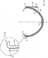
- FIG. 1A A preferred profile for the extruded metal gutter 1 is illustrated in Figure 1A . It has a channel-shaped cross-section with a substantially elliptical profile.
- the gutter 1 could, of course, be of any profile, but the profile illustrated is generally better at avoiding clogging through the build up of debris and is often referred to as a "deep flow" profile. If the profile is symmetrical as shown, then it has the advantage that it does not matter which way round it is installed in a gutter union.
- the gutter 1 is preferably extruded in three metre lengths for ease of handling, but other lengths are of course possible.
- the top-edges 2 of the gutter 1 are each provided with a beaded lip 3 that helps to strengthen the top-edge 2 and to provide the necessary spacing between the side of the gutter 1 and the internal surface of the union when connected.
- the gutter 1 is preferably extruded from aluminium or a metal alloy based on aluminium, for example, 6063 alloy which has received a T5 hardening treatment.
- the illustrated gutter 1 has a depth of 75 mm and a width at the top of 128 mm. It is preferably provided with a polyester powder coated external finish.
- gutter sections In order to form a gutter for a roof, a number of lengths of gutter (gutter sections) will need to be joined together using unions. Stop-ends will also need to be fixed to the end of the runs, an outlet should be provided at the lowest point and angle sections may be required to negotiate corners of the building.
- additional components can be cast from metal, for example, using a high pressure casting technique, and are preferably made from aluminium or an alloy based on aluminium, for example, LM6, which is an aluminium-silicon alloy that is particularly suited to die casting. Preferably any such component is also provided with a polyester powder coated finish.
- Figure 2 illustrates a plan view of a preferred union
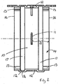
- Figure 3A illustrates the union 10 from one end
- Figure 4 is a rear elevation of the union 10.
- the union 10 is designed to accommodate, and join together, the ends of two lengths of gutter 1.
- the union 10 has a channel-shaped cross-section substantially matching that of the gutter, though is slightly larger in order to fit around the gutter, i.e., it is adapted to be mounted externally of the gutter 1. There is usually a slight gap between the bodies of these components, for example as provided by the beaded lip 3 mentioned above.
- a tab 11 is provided in the middle of the union 10 as a guide to the installer that the ends of the gutter 1 have been properly inserted.
- the top-edges 12 are provided with retaining lugs 13 for retaining the gutter 1 within the union 10.
- the retaining lugs 13 abut against the beaded lip 3 of the gutter 1 on each side of the gutter 1, in order to urge the external surface 4 of the gutter 1 towards the internal surface 14 of the union 10 in the region of overlap 15.
- Four retaining lugs 13 are provided on the union 10, one arranged on each corner where the top-edge 12 meets the side edge 16 at the mouth of the union 10.
- each retaining lug 13 extends along the top-edge 12 from the side edge 16 only to the start of a transversely extending channel 17.
- the retaining lugs are positioned outwardly of this transversely extending channel 17 and do not extend all the way to the middle of the union, for example, in contrast to the plastic gutter counterparts.
- the union 10 is preferably made by high pressure casting, where the molten metal is injected into a set of dies.
- a female die is provided to mould the external profile of the union 10 while transversely movable male dies can be used to form the two mouths of the union 10.
- Figure 4 shows a rear view of the union 10 where the bracket detail is shown more clearly.
- a hole 20 for a screw (not shown) is provided in the bracket member 18 for fastening the union 10 to a building structure.
- Additional lugs 21 are provided with holes 22 for securing the union 10 more securely to the building structure.
- circumferential ridges 23 provided in the external surface 24 of the union 10, in order to accommodate the transversely extending channels 17 provided on the internal surface 14 of the union 10.
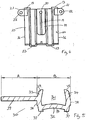
- Figure 5 shows a cross-sectional view through a strip of resilient material 30.
- a track 31 comprising a base 32 and two resilient ribs 33, 34 extending from the base 32.
- the track 31 is adapted to receive a bead of sealant (not shown).
- the profile and dimensions of the track 31 are selected in order to accommodate the bead of sealant, which would usually be applied using a conventional mastic gun type of dispenser.
- these devices are used to dispense beads of around 3 to 8 mm wide of a gunable compound and the U-shaped track 31 should be sized accordingly.
- the track 31 could be much less angular than shown and still perform the function of retaining a bead of sealant, for example, it could be more V-shaped and have no distinguishable base.
- the squarer U-shaped profile is advantageous because it provides additional stability within the transversely extending channel 17. This helps to maintain the position of the track 31 as the resilient ribs 33, 34 are bent and deflected during connection of the gutter system.
- the squarer U-shaped profile also helps to resist movement of the seal during temperature cycles.
- the resilient ribs 33, 34 are inclined slightly so as to slant inwardly, and they include a rounded top edge 35. These measures encourage the ribs 33, 34 to fold in on themselves when compressed by the gutter 1, and thereby helps to enclose the sealant within the track 31 and against the external surface 4 of the gutter 1.
- the sealant is preferably a silicone sealant, for example a low modulus, high performance silicone sealant such as Marley Alutec Code Ref: SC101.
- This sealant is a mixture based on polydimethylsioxane, fillers and curing agents, and will cure once it has been applied.
- any sealant that is able to function in this way could be used providing it has sufficiently good sealing properties and longevity, e.g., it will last for 50 years without requiring maintenance.
- a hollow 36 located beneath the base 32, which is provided for receiving a smaller amount of sealant in order to adhere the strip 30 to the transversely extending channel 17 of the union 10.
- the base 32 is curved to provide a concave hollow 36 which is perched on either side on two longitudinally extending feet 37. These feet 37 seat within the transversely extending channel 17 of the union 10. They are located stepped within the widest point of the track 31, creating a concave profile to the ribs 33, 34, which further encourages the resilient ribs 33, 34 to fold inwardly on the track 31 when compressed.
- the resilient ribs 33, 34 may be provided with flat regions 38 in order to grip the sides 17a of the transversely extending channel 17 in the union 10.
- the base 32 of the track 31 may be positioned slightly higher or lower than shown according to the properties of the sealant material(s) being used and the working separation between the gutter 1 and union 10 components.
- the strip 30 is provided with a resilient tongue 39 that projects from one side of the track 31.
- This tongue 39 provides a resilient support beneath the gutter 1, which helps to lift the gutter 1 up more evenly against the retaining lugs 13 of the union 10, so that the components are encouraged to line up with one another.
- the tongue 39 provides a resilient spacer between the external surface 4 of the gutter 1 and the internal surface 14 of the union 10 in the region of overlap 15 that is directly underneath the retaining lugs 13.
- the extruded cross-section of the strip 31 can be seen to provide a gutter supporting portion A comprising the tongue 39 and a sealant retaining portion B comprising the track 31.
- the two portions A, B are approximately the same width, e.g., preferably the two portions A, B are within ⁇ 10% of being the same width.
- the thickness of the tongue 39 is preferably substantially the same as the thickness of the resilient ribs 33, 34 and the base 32, so that the portions A, B experience substantially the same processing conditions during the extrusion operation.
- Figure 6 shows a cross-section through the union 10 with a section of gutter 1 already in place on the right hand side of the figure.
- a strip 30 is shown being aligned for locating the track 31 in the transversely extending channel 17.
- the tongue 39 extends outwardly from the channel 17 towards the mouth of the union 10 (the end 16) where it will provide support for a length of gutter 1.
- the installer To assemble the metal gutter components to form a gutter or part thereof, the installer first applies a bead of sealant along the track 31, following the curvature of the track 31 around the circumferential surface.
- the bead of sealant will effectively fill up the track 31 to the top of the resilient ribs 33, 34, though in practice there are likely to be regions that are under-filled and regions that are over-filled.
- the installer offers up the union 10 so that the end of the gutter 1 forms a region of overlap 15 with the union 10.
- the external surface 4 of the gutter 1 follows adjacent the internal surface 14 of the union 10 within this region of overlap 15. There is, however, a small separation "s" between the two surfaces corresponding to the thickness of the tongue 39 and may be more.
- the relative height of the gutter 1 and the position of where the retaining lugs 13 will be on the union urges the external surface 4 of the gutter 1 against the transversely extending resilient ribs 33, 34 of the strip 30.
- the track 31 compresses, in as much as the resilient ribs 33, 34 tend to fold over inwardly into the track 31 to enclose the bead of sealant. Sealant will also flow from the track 31 to bond the strip 30 to the external surface 4 of the gutter 1. Sealant is also present in the hollow 36 below the track 31 and bonds the strip 30 to the internal surface 14 of the union 10.
- the resilient ribs 33, 34 of the track 31 give a clear visual indication to the installer to apply sealant around the entire joint, for example, all the way up the sides of the gutter joint, and not just to the base area of the gutter.
- the track 31 also gives a visual indication of how large a bead of sealant is required. The nozzle of a sealant gun can then be cut to an appropriate size.
- Another benefit is that if sealant is applied unevenly, then as the metal gutter is pushed onto the second metal gutter component, sealant is squeezed along the track 31, forming a more even bead of sealant that extends, without gaps, around the gutter joint.
- the sealant is also confined by the track 31, which helps to reduce mess and inconvenience to the installer.
- the strip 30 also serves a further function of supporting the gutter by way of the resilient tongue 39, ensuring a good aligned connection is made. Moreover with the provision of the retaining lugs 13 on the second metal gutter component, installation becomes simple for any builder who was already familiar with conventional plastic guttering. In this way, the new gutter system can be sold as a proprietary product with guarantees for a maintenance free period which exceeds those given with plastic gutter systems.
- the joint can be used on any metal gutter component that is intended to join with a length of gutter 1, for example, a gutter outlet, a gutter adapter, a gutter angle, a gutter stop, or even a further length of gutter.
- a gutter system having a gutter joint where the first metal gutter component comprises a length of metal gutter
- the channel for holding the sealant retaining portion of the strip is provided in the length of metal gutter, i.e., the first metal gutter component
- the second metal gutter might be a union, a stop or other component that fits, for example, internally within the metal gutter.
- the present invention can be seen to provide a gutter system having a gutter joint where a first metal gutter component, comprising a length of gutter, is joined to a second metal gutter component, the components overlapping at the gutter joint and the gutter joint further having a strip of resilient material that extends transversely to the metal gutter and is sandwiched between adjacent overlapping surfaces of the gutter components, wherein the first metal gutter component is provided with a channel for holding a sealant retaining portion of the strip in place, and further wherein the sealant retaining portion of the strip comprises a track that is arranged to be filled with, or has been filled with, a bead of sealant prior to joining the gutter components together to form the gutter joint.
- the strip is provided on the gutter rather than the other jointing component. All the features described above in relation to the gutter components and the strip apply equally to these arrangements.
Landscapes
- Engineering & Computer Science (AREA)
- Architecture (AREA)
- Civil Engineering (AREA)
- Structural Engineering (AREA)
- Gasket Seals (AREA)
- Roof Covering Using Slabs Or Stiff Sheets (AREA)
Claims (14)
- Système de gouttière avec joint de gouttière dans lequel un premier composant de gouttière métallique, consistant en une longueur de gouttière métallique (1), est joint à un second composant de gouttière métallique, les composants se chevauchant au niveau du joint de gouttière, et dans lequel le joint de gouttière comprend en outre une bande de matériau élastique (30) s'étendant transversalement dans la direction longitudinale de la gouttière métallique (1) et enserrée entre des surfaces chevauchantes adjacentes des composants de gouttière, l'un des composants de gouttière métallique étant muni d'un canal (17) permettant de recevoir en place une partie de la bande (30) servant à retenir un produit d'étanchéité, ainsi que des attaches de retenue intégrées (13) conçues pour retenir l'autre composant de gouttière métallique (1) dans une configuration à joint, et la partie de la bande (30) servant à retenir un produit d'étanchéité consistant en une gorge en forme de U (31) conçue pour être remplie avec un cordon de produit d'étanchéité avant de joindre les composants de gouttière pour former le joint de gouttière, la gorge (31) ayant une largeur comprise entre 3 mm et 12 mm et une profondeur d'au moins 3 mm.
- Système de gouttière selon la revendication 1, dans lequel la bande (30) comprend une languette (39) se projetant environ à partir de la moitié d'un côté de la gorge (31).
- Système de gouttière selon la revendication 2, dans lequel la bande de matériau élastique (30) comprend un monomère d'éthylène-propylène-diène extrudé ayant une section transversale comprenant la gorge (31) pour le cordon de produit d'étanchéité, et dans lequel la languette (39) se projette à partir d'un côté de la gorge (31) pour supporter la gouttière (1).
- Système de gouttière selon la revendication 1, 2 ou 3, dans lequel la gorge (31) pour le produit d'étanchéité est en forme de U et est formée à partir d'une base (32) et de deux nervures (33, 34), une de chaque côté, se projetant à partir de la base (32), les pointes (35) des nervures (33, 34) étant inclinées vers l'intérieur de la gorge (31) de manière à converger l'une vers l'autre.
- Système de gouttière selon l'une quelconque des revendications précédentes, dans lequel le produit d'étanchéité est un produit d'étanchéité à base de silicone liquide qui sèche après son application.
- Système de gouttière selon l'une quelconque des revendications précédentes, dans lequel le produit d'étanchéité a été préappliqué sur le dessous de la gorge (31) de la bande (30) afin de préfixer la bande (30) à l'un des composants de gouttière métallique.
- Système de gouttière selon l'une quelconque des revendications précédentes, dans lequel le second composant de gouttière métallique est une jonction de gouttière (10) ou une butée de gouttière qui s'ajuste de façon externe à la gouttière et qui est munie du canal (17) permettant de recevoir une partie de la bande (30) servant à retenir le produit d'étanchéité.
- Système de gouttière selon l'une quelconque des revendications précédentes, dans lequel le second composant de gouttière métallique a été formé par un procédé de coulage de métal à haute pression.
- Système de gouttière selon l'une quelconque des revendications précédentes, dans lequel les attaches de retenue intégrées (13) sont situées sur les bords supérieurs du second composant de gouttière métallique (10) afin de retenir la gouttière métallique (1).
- Système de gouttière selon la revendication 9, dans lequel les attaches de retenue sont décalées par rapport à la gorge (31) de la bande (30).
- Procédé de formation d'un joint de gouttière dans un système de gouttière carrée entre un premier composant de gouttière métallique, consistant en une longueur de gouttière métallique à section carrée, et un second composant de gouttière métallique, le procédé comprenant les étapes consistant à :fournir une bande de matériau élastique (30) dans une région où la gouttière métallique chevauche le second composant de gouttière métallique au niveau du joint de gouttière, la bande (30) comprenant une gorge en forme de U (31) permettant de recevoir un produit d'étanchéité et ayant une largeur comprise entre 3 mm et 12 mm et une profondeur d'au moins 3 mm ;appliquer un cordon de produit d'étanchéité dans la gorge (31) de la bande (30) ;rapprocher la gouttière métallique à section carrée du second composant de gouttière métallique en engageant un bord supérieur arrière de la gouttière sous une attache de retenue (13) du second composant de gouttière métallique ; etpousser un bord avant de la gouttière sous une autre attache de retenue du second composant de gouttière métallique afin de bloquer la gouttière en position chevauchée par le second composant de gouttière métallique, de manière à enserrer la bande (30) et le cordon de produit d'étanchéité entre les surfaces adjacentes de la gouttière métallique carrée et du second composant de gouttière métallique, afin de former le joint de gouttière.
- Procédé selon la revendication 11, dans lequel l'étape consistant à appliquer un cordon de produit d'étanchéité consiste à approcher une buse d'un distributeur de produit d'étanchéité et à appliquer un cordon de produit d'étanchéité de silicone dans la gorge (31) de la bande (30) avant de former le joint de gouttière.
- Procédé selon la revendication 11 ou 12, dans lequel l'étape consistant à fournir un matériau élastique de bande (30) consiste à fournir une bande moulée par injection d'un matériau élastique (30) dont le profil correspond à la forme carrée de la gouttière comportant des cordons préformés conçus pour se situer dans les coins de la surface intérieure du second composant de gouttière métallique.
- Procédé selon la revendication 11, 12 ou 13, dans lequel la bande (30) comprend en outre une attache (39) permettant de supporter la gouttière.
Applications Claiming Priority (1)
| Application Number | Priority Date | Filing Date | Title |
|---|---|---|---|
| GBGB0916605.9A GB0916605D0 (en) | 2009-09-21 | 2009-09-21 | Improved metal gutter system |
Publications (3)
| Publication Number | Publication Date |
|---|---|
| EP2302147A2 EP2302147A2 (fr) | 2011-03-30 |
| EP2302147A3 EP2302147A3 (fr) | 2011-04-27 |
| EP2302147B1 true EP2302147B1 (fr) | 2016-03-30 |
Family
ID=41327381
Family Applications (1)
| Application Number | Title | Priority Date | Filing Date |
|---|---|---|---|
| EP10178104.5A Active EP2302147B1 (fr) | 2009-09-21 | 2010-09-21 | Système de gouttière métallique avec raccordement amélioré |
Country Status (3)
| Country | Link |
|---|---|
| EP (1) | EP2302147B1 (fr) |
| GB (2) | GB0916605D0 (fr) |
| PL (1) | PL2302147T3 (fr) |
Families Citing this family (1)
| Publication number | Priority date | Publication date | Assignee | Title |
|---|---|---|---|---|
| JP6491953B2 (ja) * | 2015-05-15 | 2019-03-27 | 鹿島建設株式会社 | 拘束体、及び、部材の設置方法 |
Family Cites Families (7)
| Publication number | Priority date | Publication date | Assignee | Title |
|---|---|---|---|---|
| GB1603819A (en) * | 1978-05-31 | 1981-12-02 | Wavin Bv | Guttering |
| US4327051A (en) * | 1978-07-06 | 1982-04-27 | Plastiers Limited | Method of molding gutter fittings |
| GB2026058B (en) * | 1978-07-19 | 1983-02-09 | Pre Formed Components Ltd | Joint sealing |
| FR2533958A1 (fr) * | 1982-09-30 | 1984-04-06 | Ambroise Casterot Francis | Perfectionnements aux dispositifs de jonction de gouttieres |
| GB2193982A (en) * | 1986-08-08 | 1988-02-24 | Allfor Investment Limited | Gutter joint |
| DE4202136A1 (de) * | 1991-02-08 | 1992-08-13 | Gerhard Arlt | Verbindungsvorrichtung fuer dachrinnen aus metall und fuer deren zubehoerteile |
| GB0102007D0 (en) * | 2001-01-25 | 2001-03-14 | Marley Extrusions | Sealed joints |
-
2009
- 2009-09-21 GB GBGB0916605.9A patent/GB0916605D0/en not_active Ceased
-
2010
- 2010-09-21 EP EP10178104.5A patent/EP2302147B1/fr active Active
- 2010-09-21 PL PL10178104.5T patent/PL2302147T3/pl unknown
- 2010-09-21 GB GB1015813.7A patent/GB2473941B/en not_active Expired - Fee Related
Also Published As
| Publication number | Publication date |
|---|---|
| GB2473941A (en) | 2011-03-30 |
| GB0916605D0 (en) | 2009-11-04 |
| EP2302147A2 (fr) | 2011-03-30 |
| EP2302147A3 (fr) | 2011-04-27 |
| PL2302147T3 (pl) | 2016-09-30 |
| GB201015813D0 (en) | 2010-10-27 |
| GB2473941B (en) | 2012-10-03 |
Similar Documents
| Publication | Publication Date | Title |
|---|---|---|
| AU2016219574B2 (en) | Sealing gland | |
| US4083158A (en) | Coping mounting plate | |
| US5123208A (en) | Reglet assembly with snap-on flashing | |
| US8646237B1 (en) | Sealing retention clip | |
| RU2630944C2 (ru) | Профилированный элемент для соединения стекла транспортного средства с деталью обшивки и узел профилированного элемента | |
| CA2073214C (fr) | Solin pour membrane d'etancheite pour toitures | |
| RU2006119436A (ru) | Панельный элемент с рамой, и способ ее изготовления | |
| US7874106B2 (en) | Sill flashing and end dam assembly | |
| WO2005118996A1 (fr) | Appareil et procede permettant d'obtenir un solin pour linteau de porte et de fenetre | |
| CA2023344A1 (fr) | Courronnement pour mur parapet non uniforme | |
| US6108981A (en) | Surface mount counter flashing system | |
| US10697181B2 (en) | Edge metal system | |
| US20110211933A1 (en) | Attachment fastener with a sealing washer | |
| TW201937047A (zh) | 被覆之改進及其相關 | |
| US9187905B2 (en) | Roof or window panel to metal roofing or siding interface securement system | |
| EP2302147B1 (fr) | Système de gouttière métallique avec raccordement amélioré | |
| US10745910B2 (en) | Wet seal system | |
| EP1493877A2 (fr) | Elément étanche de construction | |
| JPH08218502A (ja) | 外壁パネルの目地用シーリング材の構造 | |
| RU2060428C1 (ru) | Стыковое соединение между двумя плоскоовальными трубчатыми секциями из листового металла | |
| MX2009000485A (es) | Cierres hidraulicos moldeados por inyeccion de doble ciclo de moldeo. | |
| JP4112435B2 (ja) | 目地構造 | |
| JP7348111B2 (ja) | 目地状部分の止水部材及び目地状部分の止水構造 | |
| US5518336A (en) | Drainage gutter and method of installing | |
| US11015380B2 (en) | Dead stop type projection windows with sealant dams for controlling flow of sealant during installation of insert windows |
Legal Events
| Date | Code | Title | Description |
|---|---|---|---|
| PUAI | Public reference made under article 153(3) epc to a published international application that has entered the european phase |
Free format text: ORIGINAL CODE: 0009012 |
|
| PUAL | Search report despatched |
Free format text: ORIGINAL CODE: 0009013 |
|
| AK | Designated contracting states |
Kind code of ref document: A2 Designated state(s): AL AT BE BG CH CY CZ DE DK EE ES FI FR GB GR HR HU IE IS IT LI LT LU LV MC MK MT NL NO PL PT RO SE SI SK SM TR |
|
| AX | Request for extension of the european patent |
Extension state: BA ME RS |
|
| AK | Designated contracting states |
Kind code of ref document: A3 Designated state(s): AL AT BE BG CH CY CZ DE DK EE ES FI FR GB GR HR HU IE IS IT LI LT LU LV MC MK MT NL NO PL PT RO SE SI SK SM TR |
|
| AX | Request for extension of the european patent |
Extension state: BA ME RS |
|
| 17P | Request for examination filed |
Effective date: 20111027 |
|
| 17Q | First examination report despatched |
Effective date: 20150512 |
|
| RAP1 | Party data changed (applicant data changed or rights of an application transferred) |
Owner name: MARLEY ALUTEC LIMITED |
|
| GRAP | Despatch of communication of intention to grant a patent |
Free format text: ORIGINAL CODE: EPIDOSNIGR1 |
|
| INTG | Intention to grant announced |
Effective date: 20151110 |
|
| GRAS | Grant fee paid |
Free format text: ORIGINAL CODE: EPIDOSNIGR3 |
|
| GRAA | (expected) grant |
Free format text: ORIGINAL CODE: 0009210 |
|
| AK | Designated contracting states |
Kind code of ref document: B1 Designated state(s): AL AT BE BG CH CY CZ DE DK EE ES FI FR GB GR HR HU IE IS IT LI LT LU LV MC MK MT NL NO PL PT RO SE SI SK SM TR |
|
| REG | Reference to a national code |
Ref country code: GB Ref legal event code: FG4D |
|
| REG | Reference to a national code |
Ref country code: CH Ref legal event code: EP |
|
| REG | Reference to a national code |
Ref country code: AT Ref legal event code: REF Ref document number: 785581 Country of ref document: AT Kind code of ref document: T Effective date: 20160415 |
|
| REG | Reference to a national code |
Ref country code: IE Ref legal event code: FG4D |
|
| REG | Reference to a national code |
Ref country code: DE Ref legal event code: R096 Ref document number: 602010031601 Country of ref document: DE |
|
| REG | Reference to a national code |
Ref country code: LT Ref legal event code: MG4D |
|
| PG25 | Lapsed in a contracting state [announced via postgrant information from national office to epo] |
Ref country code: HR Free format text: LAPSE BECAUSE OF FAILURE TO SUBMIT A TRANSLATION OF THE DESCRIPTION OR TO PAY THE FEE WITHIN THE PRESCRIBED TIME-LIMIT Effective date: 20160330 Ref country code: NO Free format text: LAPSE BECAUSE OF FAILURE TO SUBMIT A TRANSLATION OF THE DESCRIPTION OR TO PAY THE FEE WITHIN THE PRESCRIBED TIME-LIMIT Effective date: 20160630 Ref country code: FI Free format text: LAPSE BECAUSE OF FAILURE TO SUBMIT A TRANSLATION OF THE DESCRIPTION OR TO PAY THE FEE WITHIN THE PRESCRIBED TIME-LIMIT Effective date: 20160330 Ref country code: GR Free format text: LAPSE BECAUSE OF FAILURE TO SUBMIT A TRANSLATION OF THE DESCRIPTION OR TO PAY THE FEE WITHIN THE PRESCRIBED TIME-LIMIT Effective date: 20160701 |
|
| REG | Reference to a national code |
Ref country code: NL Ref legal event code: MP Effective date: 20160330 |
|
| REG | Reference to a national code |
Ref country code: AT Ref legal event code: MK05 Ref document number: 785581 Country of ref document: AT Kind code of ref document: T Effective date: 20160330 |
|
| PG25 | Lapsed in a contracting state [announced via postgrant information from national office to epo] |
Ref country code: SE Free format text: LAPSE BECAUSE OF FAILURE TO SUBMIT A TRANSLATION OF THE DESCRIPTION OR TO PAY THE FEE WITHIN THE PRESCRIBED TIME-LIMIT Effective date: 20160330 Ref country code: LT Free format text: LAPSE BECAUSE OF FAILURE TO SUBMIT A TRANSLATION OF THE DESCRIPTION OR TO PAY THE FEE WITHIN THE PRESCRIBED TIME-LIMIT Effective date: 20160330 Ref country code: LV Free format text: LAPSE BECAUSE OF FAILURE TO SUBMIT A TRANSLATION OF THE DESCRIPTION OR TO PAY THE FEE WITHIN THE PRESCRIBED TIME-LIMIT Effective date: 20160330 |
|
| REG | Reference to a national code |
Ref country code: FR Ref legal event code: PLFP Year of fee payment: 7 |
|
| PG25 | Lapsed in a contracting state [announced via postgrant information from national office to epo] |
Ref country code: NL Free format text: LAPSE BECAUSE OF FAILURE TO SUBMIT A TRANSLATION OF THE DESCRIPTION OR TO PAY THE FEE WITHIN THE PRESCRIBED TIME-LIMIT Effective date: 20160330 |
|
| PG25 | Lapsed in a contracting state [announced via postgrant information from national office to epo] |
Ref country code: IS Free format text: LAPSE BECAUSE OF FAILURE TO SUBMIT A TRANSLATION OF THE DESCRIPTION OR TO PAY THE FEE WITHIN THE PRESCRIBED TIME-LIMIT Effective date: 20160730 Ref country code: EE Free format text: LAPSE BECAUSE OF FAILURE TO SUBMIT A TRANSLATION OF THE DESCRIPTION OR TO PAY THE FEE WITHIN THE PRESCRIBED TIME-LIMIT Effective date: 20160330 |
|
| PG25 | Lapsed in a contracting state [announced via postgrant information from national office to epo] |
Ref country code: RO Free format text: LAPSE BECAUSE OF FAILURE TO SUBMIT A TRANSLATION OF THE DESCRIPTION OR TO PAY THE FEE WITHIN THE PRESCRIBED TIME-LIMIT Effective date: 20160330 Ref country code: SM Free format text: LAPSE BECAUSE OF FAILURE TO SUBMIT A TRANSLATION OF THE DESCRIPTION OR TO PAY THE FEE WITHIN THE PRESCRIBED TIME-LIMIT Effective date: 20160330 Ref country code: SK Free format text: LAPSE BECAUSE OF FAILURE TO SUBMIT A TRANSLATION OF THE DESCRIPTION OR TO PAY THE FEE WITHIN THE PRESCRIBED TIME-LIMIT Effective date: 20160330 Ref country code: PT Free format text: LAPSE BECAUSE OF FAILURE TO SUBMIT A TRANSLATION OF THE DESCRIPTION OR TO PAY THE FEE WITHIN THE PRESCRIBED TIME-LIMIT Effective date: 20160801 Ref country code: ES Free format text: LAPSE BECAUSE OF FAILURE TO SUBMIT A TRANSLATION OF THE DESCRIPTION OR TO PAY THE FEE WITHIN THE PRESCRIBED TIME-LIMIT Effective date: 20160330 Ref country code: CZ Free format text: LAPSE BECAUSE OF FAILURE TO SUBMIT A TRANSLATION OF THE DESCRIPTION OR TO PAY THE FEE WITHIN THE PRESCRIBED TIME-LIMIT Effective date: 20160330 Ref country code: AT Free format text: LAPSE BECAUSE OF FAILURE TO SUBMIT A TRANSLATION OF THE DESCRIPTION OR TO PAY THE FEE WITHIN THE PRESCRIBED TIME-LIMIT Effective date: 20160330 |
|
| PG25 | Lapsed in a contracting state [announced via postgrant information from national office to epo] |
Ref country code: IT Free format text: LAPSE BECAUSE OF FAILURE TO SUBMIT A TRANSLATION OF THE DESCRIPTION OR TO PAY THE FEE WITHIN THE PRESCRIBED TIME-LIMIT Effective date: 20160330 |
|
| REG | Reference to a national code |
Ref country code: DE Ref legal event code: R097 Ref document number: 602010031601 Country of ref document: DE |
|
| PG25 | Lapsed in a contracting state [announced via postgrant information from national office to epo] |
Ref country code: DK Free format text: LAPSE BECAUSE OF FAILURE TO SUBMIT A TRANSLATION OF THE DESCRIPTION OR TO PAY THE FEE WITHIN THE PRESCRIBED TIME-LIMIT Effective date: 20160330 |
|
| PLBE | No opposition filed within time limit |
Free format text: ORIGINAL CODE: 0009261 |
|
| STAA | Information on the status of an ep patent application or granted ep patent |
Free format text: STATUS: NO OPPOSITION FILED WITHIN TIME LIMIT |
|
| 26N | No opposition filed |
Effective date: 20170103 |
|
| PG25 | Lapsed in a contracting state [announced via postgrant information from national office to epo] |
Ref country code: MC Free format text: LAPSE BECAUSE OF FAILURE TO SUBMIT A TRANSLATION OF THE DESCRIPTION OR TO PAY THE FEE WITHIN THE PRESCRIBED TIME-LIMIT Effective date: 20160330 |
|
| REG | Reference to a national code |
Ref country code: CH Ref legal event code: PL |
|
| PG25 | Lapsed in a contracting state [announced via postgrant information from national office to epo] |
Ref country code: SI Free format text: LAPSE BECAUSE OF FAILURE TO SUBMIT A TRANSLATION OF THE DESCRIPTION OR TO PAY THE FEE WITHIN THE PRESCRIBED TIME-LIMIT Effective date: 20160330 |
|
| PG25 | Lapsed in a contracting state [announced via postgrant information from national office to epo] |
Ref country code: LI Free format text: LAPSE BECAUSE OF NON-PAYMENT OF DUE FEES Effective date: 20160930 Ref country code: CH Free format text: LAPSE BECAUSE OF NON-PAYMENT OF DUE FEES Effective date: 20160930 |
|
| PG25 | Lapsed in a contracting state [announced via postgrant information from national office to epo] |
Ref country code: LU Free format text: LAPSE BECAUSE OF NON-PAYMENT OF DUE FEES Effective date: 20160921 |
|
| REG | Reference to a national code |
Ref country code: FR Ref legal event code: PLFP Year of fee payment: 8 |
|
| PG25 | Lapsed in a contracting state [announced via postgrant information from national office to epo] |
Ref country code: HU Free format text: LAPSE BECAUSE OF FAILURE TO SUBMIT A TRANSLATION OF THE DESCRIPTION OR TO PAY THE FEE WITHIN THE PRESCRIBED TIME-LIMIT; INVALID AB INITIO Effective date: 20100921 Ref country code: CY Free format text: LAPSE BECAUSE OF FAILURE TO SUBMIT A TRANSLATION OF THE DESCRIPTION OR TO PAY THE FEE WITHIN THE PRESCRIBED TIME-LIMIT Effective date: 20160330 |
|
| PG25 | Lapsed in a contracting state [announced via postgrant information from national office to epo] |
Ref country code: MK Free format text: LAPSE BECAUSE OF FAILURE TO SUBMIT A TRANSLATION OF THE DESCRIPTION OR TO PAY THE FEE WITHIN THE PRESCRIBED TIME-LIMIT Effective date: 20160330 Ref country code: MT Free format text: LAPSE BECAUSE OF NON-PAYMENT OF DUE FEES Effective date: 20160930 Ref country code: TR Free format text: LAPSE BECAUSE OF FAILURE TO SUBMIT A TRANSLATION OF THE DESCRIPTION OR TO PAY THE FEE WITHIN THE PRESCRIBED TIME-LIMIT Effective date: 20160330 |
|
| PG25 | Lapsed in a contracting state [announced via postgrant information from national office to epo] |
Ref country code: BG Free format text: LAPSE BECAUSE OF FAILURE TO SUBMIT A TRANSLATION OF THE DESCRIPTION OR TO PAY THE FEE WITHIN THE PRESCRIBED TIME-LIMIT Effective date: 20160330 |
|
| REG | Reference to a national code |
Ref country code: FR Ref legal event code: PLFP Year of fee payment: 9 |
|
| PG25 | Lapsed in a contracting state [announced via postgrant information from national office to epo] |
Ref country code: AL Free format text: LAPSE BECAUSE OF FAILURE TO SUBMIT A TRANSLATION OF THE DESCRIPTION OR TO PAY THE FEE WITHIN THE PRESCRIBED TIME-LIMIT Effective date: 20160330 |
|
| REG | Reference to a national code |
Ref country code: GB Ref legal event code: 732E Free format text: REGISTERED BETWEEN 20221013 AND 20221019 |
|
| REG | Reference to a national code |
Ref country code: BE Ref legal event code: PD Owner name: MARLEY PLASTICS LIMITED; GB Free format text: DETAILS ASSIGNMENT: CHANGE OF OWNER(S), ASSIGNMENT; FORMER OWNER NAME: MARLEY ALUTEC LIMITED Effective date: 20221221 |
|
| REG | Reference to a national code |
Ref country code: DE Ref legal event code: R082 Ref document number: 602010031601 Country of ref document: DE Representative=s name: FORRESTERS IP LLP, DE Ref country code: DE Ref legal event code: R081 Ref document number: 602010031601 Country of ref document: DE Owner name: MARLEY PLASTICS LIMITED, MAIDSTONE, GB Free format text: FORMER OWNER: MARLEY ALUTEC LTD., LENHAM MAIDSTONE, KENT, GB Ref country code: DE Ref legal event code: R082 Ref document number: 602010031601 Country of ref document: DE Representative=s name: KUEHR, VERA, DIPL.-BIOL., DE |
|
| P01 | Opt-out of the competence of the unified patent court (upc) registered |
Effective date: 20230530 |
|
| REG | Reference to a national code |
Ref country code: GB Ref legal event code: 732E Free format text: REGISTERED BETWEEN 20230907 AND 20230913 |
|
| REG | Reference to a national code |
Ref country code: DE Ref legal event code: R082 Ref document number: 602010031601 Country of ref document: DE Representative=s name: FORRESTERS IP LLP, DE |
|
| PGFP | Annual fee paid to national office [announced via postgrant information from national office to epo] |
Ref country code: PL Payment date: 20230907 Year of fee payment: 14 Ref country code: FR Payment date: 20230928 Year of fee payment: 14 Ref country code: DE Payment date: 20230920 Year of fee payment: 14 Ref country code: BE Payment date: 20230920 Year of fee payment: 14 |
|
| REG | Reference to a national code |
Ref country code: BE Ref legal event code: QB Free format text: DETAILS LICENCE: LICENCE, NEW LICENCE REGISTRATION Effective date: 20230829 |
|
| REG | Reference to a national code |
Ref country code: DE Ref legal event code: R119 Ref document number: 602010031601 Country of ref document: DE |
|
| PG25 | Lapsed in a contracting state [announced via postgrant information from national office to epo] |
Ref country code: DE Free format text: LAPSE BECAUSE OF NON-PAYMENT OF DUE FEES Effective date: 20250401 |
|
| REG | Reference to a national code |
Ref country code: BE Ref legal event code: MM Effective date: 20240930 |
|
| PG25 | Lapsed in a contracting state [announced via postgrant information from national office to epo] |
Ref country code: BE Free format text: LAPSE BECAUSE OF NON-PAYMENT OF DUE FEES Effective date: 20240930 |
|
| PG25 | Lapsed in a contracting state [announced via postgrant information from national office to epo] |
Ref country code: FR Free format text: LAPSE BECAUSE OF NON-PAYMENT OF DUE FEES Effective date: 20240930 |
|
| PGFP | Annual fee paid to national office [announced via postgrant information from national office to epo] |
Ref country code: GB Payment date: 20250704 Year of fee payment: 16 |
|
| PGFP | Annual fee paid to national office [announced via postgrant information from national office to epo] |
Ref country code: IE Payment date: 20250918 Year of fee payment: 16 |
|
| PG25 | Lapsed in a contracting state [announced via postgrant information from national office to epo] |
Ref country code: PL Free format text: LAPSE BECAUSE OF NON-PAYMENT OF DUE FEES Effective date: 20240921 |