EP2302154A2 - Régulation de fermeture pour une porte pivotante et coulissante, notamment pour des applications anti-incendie - Google Patents
Régulation de fermeture pour une porte pivotante et coulissante, notamment pour des applications anti-incendie Download PDFInfo
- Publication number
- EP2302154A2 EP2302154A2 EP10010802A EP10010802A EP2302154A2 EP 2302154 A2 EP2302154 A2 EP 2302154A2 EP 10010802 A EP10010802 A EP 10010802A EP 10010802 A EP10010802 A EP 10010802A EP 2302154 A2 EP2302154 A2 EP 2302154A2
- Authority
- EP
- European Patent Office
- Prior art keywords
- sliding
- door
- rotary wing
- door construction
- construction
- Prior art date
- Legal status (The legal status is an assumption and is not a legal conclusion. Google has not performed a legal analysis and makes no representation as to the accuracy of the status listed.)
- Granted
Links
Images

Classifications
-
- E—FIXED CONSTRUCTIONS
- E06—DOORS, WINDOWS, SHUTTERS, OR ROLLER BLINDS IN GENERAL; LADDERS
- E06B—FIXED OR MOVABLE CLOSURES FOR OPENINGS IN BUILDINGS, VEHICLES, FENCES OR LIKE ENCLOSURES IN GENERAL, e.g. DOORS, WINDOWS, BLINDS, GATES
- E06B3/00—Window sashes, door leaves, or like elements for closing wall or like openings; Layout of fixed or moving closures, e.g. windows in wall or like openings; Features of rigidly-mounted outer frames relating to the mounting of wing frames
- E06B3/32—Arrangements of wings characterised by the manner of movement; Arrangements of movable wings in openings; Features of wings or frames relating solely to the manner of movement of the wing
- E06B3/50—Arrangements of wings characterised by the manner of movement; Arrangements of movable wings in openings; Features of wings or frames relating solely to the manner of movement of the wing with more than one kind of movement
-
- E—FIXED CONSTRUCTIONS
- E05—LOCKS; KEYS; WINDOW OR DOOR FITTINGS; SAFES
- E05F—DEVICES FOR MOVING WINGS INTO OPEN OR CLOSED POSITION; CHECKS FOR WINGS; WING FITTINGS NOT OTHERWISE PROVIDED FOR, CONCERNED WITH THE FUNCTIONING OF THE WING
- E05F5/00—Braking devices, e.g. checks; Stops; Buffers
- E05F5/12—Braking devices, e.g. checks; Stops; Buffers specially for preventing the closing of a wing before another wing has been closed
-
- E—FIXED CONSTRUCTIONS
- E06—DOORS, WINDOWS, SHUTTERS, OR ROLLER BLINDS IN GENERAL; LADDERS
- E06B—FIXED OR MOVABLE CLOSURES FOR OPENINGS IN BUILDINGS, VEHICLES, FENCES OR LIKE ENCLOSURES IN GENERAL, e.g. DOORS, WINDOWS, BLINDS, GATES
- E06B3/00—Window sashes, door leaves, or like elements for closing wall or like openings; Layout of fixed or moving closures, e.g. windows in wall or like openings; Features of rigidly-mounted outer frames relating to the mounting of wing frames
- E06B3/32—Arrangements of wings characterised by the manner of movement; Arrangements of movable wings in openings; Features of wings or frames relating solely to the manner of movement of the wing
- E06B3/50—Arrangements of wings characterised by the manner of movement; Arrangements of movable wings in openings; Features of wings or frames relating solely to the manner of movement of the wing with more than one kind of movement
- E06B3/5054—Arrangements of wings characterised by the manner of movement; Arrangements of movable wings in openings; Features of wings or frames relating solely to the manner of movement of the wing with more than one kind of movement where the sliding and rotating movements are independent of each other
- E06B3/5081—Arrangements of wings characterised by the manner of movement; Arrangements of movable wings in openings; Features of wings or frames relating solely to the manner of movement of the wing with more than one kind of movement where the sliding and rotating movements are independent of each other at least two wings have a different kind of movement
-
- E—FIXED CONSTRUCTIONS
- E05—LOCKS; KEYS; WINDOW OR DOOR FITTINGS; SAFES
- E05Y—INDEXING SCHEME ASSOCIATED WITH SUBCLASSES E05D AND E05F, RELATING TO CONSTRUCTION ELEMENTS, ELECTRIC CONTROL, POWER SUPPLY, POWER SIGNAL OR TRANSMISSION, USER INTERFACES, MOUNTING OR COUPLING, DETAILS, ACCESSORIES, AUXILIARY OPERATIONS NOT OTHERWISE PROVIDED FOR, APPLICATION THEREOF
- E05Y2900/00—Application of doors, windows, wings or fittings thereof
- E05Y2900/10—Application of doors, windows, wings or fittings thereof for buildings or parts thereof
- E05Y2900/13—Type of wing
- E05Y2900/132—Doors
Definitions
- the present invention relates to a Schlueß mergewortvorraum for a particular designed for fire protection door construction with a Schlebeeriel and a rotary wing, wherein the sliding leaf and the rotary wing are arranged directly adjacent to each other and open in the opposite direction.
- the invention furthermore relates to a door construction, in particular for fire protection purposes, with a wing and a rotary wing, wherein the sliding leaf and the rotary wing are arranged directly next to one another and open in the opposite direction, the door construction being provided with a closing sequence control device according to the invention.
- door structures in particular fire doors for installation in fixed fire protection partitions in numerous embodiments and embodiments are known.
- DE 298 19 678 U1 a fire protection partition made of glass, into which a single-wing revolving door is integrated.
- the door leaf of the revolving door consists of a fire protection frame enclosed in a wooden frame, which is hinged to a door frame via hinges attached to the wooden frame. While such door designs are suitable for passage of people, larger items or vehicles can not be moved through because of the limited doorway cut-outs of these doors.
- Closure sequence controls for doors in numerous configurations are also known in the prior art, which ensure the correct sequence when closing double-leaf door constructs.
- the door key of a swing door is connected to a lever arm with a recessed in the door frame of the door construction slide rail.
- the lever arm engages in the slide rail in a slide, which is connected to the lever arm by means of a screw.
- the closing sequence control between the Belden slide and revolving door wings via a push member or a push rod, which triggers a locking device.
- the present invention has the object, while avoiding the described disadvantages of the prior art, a Schlueß passregelung for a sliding revolving door construction, preferably for a sliding revolving door according to the DE 20 2009 000 114 U1 , To set up, which in a simple and cost-effective manner In particular, a functionally reliable closing allows.
- a closing sequence control device for a particular designed for fire protection door construction with a Schlebeeriel and a rotary wing, the sliding leaf and the rotary wing are arranged directly adjacent to each other and open in the opposite direction proposed, which is characterized that when closing the door construction of the rotary door of the door construction can only be brought into Schlleßwolf when the sliding door of the door construction is in the closed position.
- the drive means of the rotary vane is provided in a preferred embodiment of the invention by or with a so-called Mosschlleßer.
- the drive means or the door closer of the closing sequence control device according to the invention allows vortellhaft tone an independent closing of the threat of the door construction, which is particularly advantageous in the case of trained for fire protection door construction. Vortellhaftetweise the drive means or the door closer purely mechanical, electrical, hydraullsch and / or pneumatically driven.
- a lever arm is attached to the drive means or Mosschlleßer the rotary door of the door construction, wherein one end of the lever arm is connected to an upper edge of the rotary door of the door construction and the other end of the lever arm in a in a slide rail of the frame enclosing the door structure sliding Gleltelement or the other end of the lever arm is connected to the sliding in the slide rail of the frame of the door construction sliding element.
- the Schlleß hotelwortvorsch invention is advantageously characterized by an associated with the rotary wing of the door construction Gleltelement cooperating in the Gleltschiene locking device with at least one trigger member, wherein the rotary wing of the door construction in the triggered state of the spanner in Schlleß ein can be brought.
- the closing sequence control device is further advantageously characterized by a sliding in the slide rail of the frame of the door structure sliding element, which cooperates with the trigger member of the locking device and the sliding leaf of the door construction, preferably such that the Trigger member Sperworrlchtung is actuated when the slider is moved from the sliding sash of the door construction by moving into the closed position.
- the cooperating with the sliding leaf of the door construction sliding is advantageousafterweise against the force of a spring in the slide displaced.
- the sliding element is against the force of the spring of the Schlebeeriel the door structure by shifting in Schlleß ein be brought.
- a further preferred embodiment of the invention is characterized in that the sliding element with the force of the spring from the closed position in a locking device not triggering open position can be brought, when the sliding panel of the door construction is moved by moving from the closed position to an open position.
- the spring is formed in a preferred embodiment of the invention as a return spring.
- the cooperating with the trigger member of the Sperrvorritung and with the sliding leaf of the door construction sliding element is arranged in a closed region of the Schlebeulatels the door construction in the Gleltschiene.
- the sliding leaf of the door construction of a acting in the closing direction preferably automatic Antriebmlttel movable.
- the automatic drive means of the Schlebeeriels or Schiebetors is provided in a preferred embodiment of the invention by or with a motor drive.
- the automatic drive means of the sliding leaf or sliding gate can be provided according to the invention by counterweights, spring rope pulleys and / or inclined planes.
- the drive means of the Seh packaged magnetic swirlwortvorraum invention allows vortellhaft wash an automatic closing automatic schlies around the Schlebeeriels or sliding gate of the door construction, which is particularly advantageous in the case of trained for fire protection door construction.
- the drive means is purely mechanically, electrically, hydraulically and / or pneumatically driven.
- the subject of the present invention is furthermore a door construction with a sash wing and a rotary wing, which is vororthafterhaft water for fire protection purposes, wherein the sliding sash and the rotary wing are arranged directly adjacent to each other and open in the opposite direction, which is characterized in that it has a Schlleß mergewortvorrlchtung invention.
- the Schlebeeriel and the rotary wing are open in the opposite direction.
- the rotary wing is struck on an outer side of the door construction, for example by means of door hinges, while the opening mechanism of the sliding leaf is designed so that this opening of the wing wing must be moved away from the rotary wing by moving.
- rotary doors are mounted in a dreiseitlgen door frame, of which the door hinges are attached to a perpendicular to the ground or underground Zargentell, while on the opposite perpendicular to the ground or, running surface frame part, a strike plate is attached.
- the invention is now based on the finding that the construction of the door construction according to the invention makes it possible to dispense with the frame part which is otherwise perpendicular to the floor or base, because the edge of a sash positioned next to the rotary sash faces the sash Function can take over without the fire protection properties of the entire door construction are significantly deteriorated.
- both wings of the door construction according to the invention are independent of each other and also because of the smaller size easy to use.
- the closing sequence control device according to the invention for example, only open the sliding sash and close or alternatively also the rotary wing.
- both wings of the door structure according to the invention are more or less in the same place. If, for example, it turns out that an object that is caused by the If the rotary wing is to be transported through, too wide for this one, the sliding panel must only be pushed so far that the passage has a sufficient gap. It is therefore not necessary to bring the object from the rotary wing to a possibly larger door located elsewhere, nor is it necessary to fully open the larger door. Due to the combination of rotary and sliding sash according to the invention for closing a through opening, a closable opening of variable width can be created in a fire protection partition or in another wall.
- the sliding door can also be designed to be electrically, hydraulically and / or pneumatically operable in a manner known per se, or the displaceability can be facilitated by means of cables.
- the door construction according to the invention also allows the construction of optically homogeneous fire-resistant partitions with fixed fire glass elements, since the rotary wing, the sliding sash and the fixed fire glass elements can be made in the same height if necessary.
- the rotary wing has a closing mechanism, which locks when the rotary wing is closed in a receptacle located in the sliding leaf.
- a lock mechanism which can be used according to the invention is, for example, a lock catch which is actuated via a door pawl attached to the rotary wing, wherein the lock catch is pulled out of the receptacle in the sliding wing and the rotary wing is released in this way.
- the closing mechanism together with the door can for example be integrated in a lock housing.
- a Rothblildung the door structure according to the invention provides that the rotary wing and / or the sliding leaf each having a single, continuous fire protection pane.
- the wing elements of the door construction according to the invention may have frame parts or a circumferential frame or a circumferential profile, in which case, their strength is preferably chosen so that the surface of the continuous fire protection is as large as possible, but without jeopardizing the Stabllltusch the construction.
- a material for the frame is preferably solid wood used because it changes its carrying capacity only slightly in case of fire.
- other materials that can be used for frame protection against fire such as steel, aluminum, plastic or composite materials made of steel, aluminum. Plastic and / or wood.
- the rotary wing is designed frameless.
- the door hinges and optionally the locking mechanism are attached directly to the fire panel of the rotary wing.
- a door construction according to this embodiment is characterized by a particularly high light transmission and also has a visually appealing appearance. If the fire panel contains toughened safety glass, the openings required to accommodate the lock mechanism and for the passage of the hinges are applied prior to tensioning the slab glass.
- the sliding leaf at least on its side facing the rotary wing abutting edge on a frame part, in which the receptacle is provided for the closing mechanism of the rotary wing.
- This frame part may preferably be made of solid wood or another material which can be used in frames for the frame. This is particularly advantageous, since when assembling the door construction according to the invention on the construction site, the receptacle can be more easily adjusted in a frame part than if the receptacle is located directly in or on the fire protection pane of the sliding glide ice.
- the sliding leaf with a peripheral frame, preferably made of solid wood. In this way, more components of a sliding sash, wle floor rollers or a suspension, can be relatively easily attached.
- a further preferred embodiment of the door construction according to the invention provides that the rotary wing has an impact edge facing the sliding leaf, wherein this abutment edge and the abutting edge of the sliding leaf are step-like stepped and each have at least two steps. So they are each other facing abutting edges of rotary wing and sliding sash stepped, each with at least two stages graded.
- This design of the above-mentioned abutting edges advantageously allows a good seal between the two wings of the door construction according to the invention, which is particularly important in case of fire.
- At least one of the stages is provided with a vaporiser.
- the sealing means additionally acts as a damping means when the door construction is closed.
- the mechanical load when slamming the rotary wing can be reduced.
- a sealant advantageously elongated lip seals are used, which either have a self-adhesive Haftklebstoffstrelfen or have on its underside a mushroom-shaped in cross section holding profile, with which the sealing strip can be snapped into a correspondingly shaped groove in the step of the wing.
- the sealing means at the sealing Rare eln in cross-section crescent-ausge generally advantageous, since this form of the sealant on the one hand has good sealing properties and on the other hand ensures that the sliding sash can slide when closing against the abutting edge of the rotary wing in the sealing seat, without damaging the sealant.
- a Dlchtungssch is provided at both stages of the abutting edges.
- the sealing means may either be attached to a wing of the door structure according to the invention or, alternatively, in such a way that either the first step of the rotary wing and the second step of the sliding leaf or the second step of the rotary wing and the first step of the sliding leaf with a sealing means are provided.
- a step-like gradation on one or belden wings of the door construction according to the invention at the other abutting edges may have either one or two stages, with a stage for sealing at the other abutting edges, that is, with the exception of the impact karts between the two flights in the door construction according to the invention, is usually sufficient.
- the step or steps of the wings of the door construction according to the invention and / or the construction site which comes in contact with them can likewise be provided with a sealing means according to the invention,
- a further embodiment of the door construction according to the invention provides that the rotary wing has a further locking possibility on the upper and / or lower side.
- This can be realized for example by a retractable in the upper and lower abutting edges of the rotary verrlegelungsq, which can engage in a corresponding cylindrical recess in the ground or located above the rotary wing camber.
- the secure locking of the rotary vane can be ensured even when the sliding leaf is open and the rotary wing thus the fixation by snapping his Schllef3mechanlsmusses missing in the recording of the sliding sash.
- At least one of the fire protection slabs has an internal intumescent fire protection substance or a fire protection gel.
- the use of these fire panels is due to their good fire protection properties at the same time high transparency of advantage.
- the hinges of the threatening wing are attached to a wall spar or a Futterzarge.
- the wall spar or the lining frame are preferably made of solid wood. In this way, the rotary wing of the door construction according to the invention can be fastened particularly reliable.
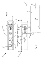
- Flg. 1 and Flg. 2 show a Schlleß mergewortvorraum 25 for a particular designed for fire protection purposes door construction 1 with a sliding sash 2 and a in the Fig. 1 and 2 not explicitly shown rotary wing 3.
- the sliding sash 2 and the rotary wing 3 of the door structure 1 are arranged directly next to each other and open in the opposite direction.
- the Schlebeeriei 2 and the rotary door 3 of the door structure 1 each one of the closing sense, automatic Antnebskar (in the Flg. 1 and 2 not explicitly shown) movable, the rotary wing 3 in particular with a so-called door closer and the sliding sash 2 in particular by so-called counterweights, Federsallrollen, inclined planes or a motor drive.
- the Schlebeeriel 2 of the door structure 1 is displaceable (In Fig. 1 and Fig. 4 represented symbolically by the double arrow marked with the reference symbol Vs) and the rotary wing 3 of the door structure 1 (shown symbolically in FIG. 4 by the double arrow marked with the reference symbol V D ).
- a lever arm On the drive means of the rotary wing 3 of the door structure 1, a lever arm is mounted, wherein one end of the lever arm is connected to an upper edge of the Drohulatels 3 of the door structure 1 and the other end of the lever arm in a displaceable in a slide rail 26 of the frame of the door structure 1 sliding member (not explicitly shown in the figures).
- the sliding member 3 associated with the rotary door 3 (not explicitly shown in the figures) cooperates with a locking device 27 arranged in the slide rail 26.
- the locking device 27 has a triggering element 28 mounted resiliently in front of the locking device.
- the trigger 28 is according to the In Flg. 2 illustrated double arrow V A pivotable.
- the locking device 27 is designed such that the rotary wing 3 of the door structure 1 in the tripped state of the locking device 27 can be brought into the closed position.
- a sliding sliding element 29 is further arranged in the slide rail 26 of the frame of the door structure 1 (shown here is the sliding door underside).
- the Verschlebonia of the sliding member 29 is in Fig. 1 represented symbolically by the indicated by the reference numeral V G double arrow.
- the sliding member 29 has in the present case a so-called Schllttenschuh 30, which cooperates with the tripping Glwick 28 of the locking device 27 such that the tripping Gll 28 of the locking device 27 is actuated when the sliding member 29 and thus the carriage shoe 30 in the direction of Fig. 1 drawn arrow A1 is moved.
- the displacement A1 of the sliding element 29 is limited by means of the sliding leaf 2 of the door construction 1, with which the sliding element 29 cooperates to trigger the locking device 27.
- the sliding member 29 a bolt 31, in this case a bolt 31, which projects into the sliding area of the sliding leaf 2 of the door structure 1, such that upon a displacement A2 of the sliding leaf 2 of the door structure 1 in the direction of in Fig. 1 Plotted arrow A2, the sliding member 29 is moved with the carriage shoe 30 in the direction of the trigger member 28 of the Spenvorides 27 (shift A1), the Auslettesglled 28 of the locking device 27 is actuated when the sliding member 29 of the sliding sash 2 of the door structure 1 by shifting A1 or A2 is moved to the closed position.
- the sliding element 29 is displaced in displacement A1 against the force of a return spring 32 in the slide rail 26, wherein the return spring 32 is fixed in the slide rail 26 by means of a spring lock 33.
- the sliding member 29 is dabel with the force of the return spring 32 saibststieri in a locking device 27 not triggering open position be brought when the sliding panel 2 of the door structure 1 is moved by moving in the opposite direction of the displacement A2 from the closed position into an open position.
- Fig. 3 and Fig. 4 show a fire door construction 1 consisting of a sliding sash 2 and a rotary wing 3.
- a marked position of the rotary wing 3 and the Schiebeflugei 2 are closed.
- the rotary leaf 3 is closed and the sliding sash 2 is opened.
- the opening direction of the Droheriels 3 is indicated by dashed arrow elnen V D.
- the sliding leaf 2 can be accessibleblldet as a full-surface wooden door or optionally have a fire protection panel 4, which is enclosed in a circumferential frame 5 made of solid wood (shown in the figures of the drawing).
- the fire protection panel 4 consists of two layers of tempered safety glass with a laminated intermediate layer of intumescent material in case of fire.
- a glass pane can altematlv and / or additionally be used according to the invention.
- the sliding sash 2 is held at an upper abutment edge 6 of its peripheral frame 5 at a Laufschlene 7, which is covered by a veneer 8,itllch slidably.
- the slide rail 26 can also be formed directly from the running rail 7.
- the circumferential frame 5 of the sliding leaf 2 Is equipped for manual opening with a Grlffmulde 9. During the opening of the Schlebeeriels 2 of the Schlebeeriel 2 of the door structure 1 is lifted by a slope of the running rail 7 lelcht simultaneously.
- the rotary wing 3 of the door structure 1 is frameless made of wood and can optionally have individual fire screens 4 or be designed as a glass door.
- the rotary wing 3 is rotatably supported by three door hinges 10 on a spar 11.
- the rotary wing 3 of the door structure 1 is provided on its side facing the sliding leaf 2 of the door structure 1 with a lock housing 15 which is fixed to the Brendtikecheibe 4 of the rotary wing 3.
- the lock housing 15 accommodates a lock mechanism comprising a lock latch. The latch bolt is pulled out by a door latch 16 from the provided in the peripheral frame 5 of the sliding panel 2 receptacle to release the rotary wing 3.
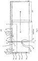
- Fig. 4 shows the lying in the Schlleß Scheme S transition region between the sliding sash 2 and the rotary wing 3 of the door structure 1 on the basis of Fig. 3 illustrated door construction 1 In a plan view along the section line IV-IV.
- the encircling frame 5 has a pivoting edge 3 facing the abutting edge 17, the Stepped stepped and has two stages 18 and 19, wherein the step 19, a sealant 20 is attached in the form of a lip seal with crescent-shaped sealing profile.
- the rotary wing 3 has a collision edge 21 which is formed stepwise over twelve stages 22 and 23, wobel on the step 23, a sealant 24 is attached in the form of a lip seal with a half-moon-shaped sealing profile.
Landscapes
- Engineering & Computer Science (AREA)
- Civil Engineering (AREA)
- Structural Engineering (AREA)
- Special Wing (AREA)
Applications Claiming Priority (1)
| Application Number | Priority Date | Filing Date | Title |
|---|---|---|---|
| DE200920013076 DE202009013076U1 (de) | 2009-09-29 | 2009-09-29 | Schließfolgeregelung für eine Schiebe-Drehtür, insbesondere für Brandschutzzwecke |
Publications (3)
| Publication Number | Publication Date |
|---|---|
| EP2302154A2 true EP2302154A2 (fr) | 2011-03-30 |
| EP2302154A3 EP2302154A3 (fr) | 2014-05-14 |
| EP2302154B1 EP2302154B1 (fr) | 2019-02-27 |
Family
ID=41462143
Family Applications (1)
| Application Number | Title | Priority Date | Filing Date |
|---|---|---|---|
| EP10010802.6A Active EP2302154B1 (fr) | 2009-09-29 | 2010-09-27 | Régulation de fermeture pour une porte pivotante et coulissante, notamment pour des applications anti-incendie |
Country Status (2)
| Country | Link |
|---|---|
| EP (1) | EP2302154B1 (fr) |
| DE (1) | DE202009013076U1 (fr) |
Cited By (1)
| Publication number | Priority date | Publication date | Assignee | Title |
|---|---|---|---|---|
| CN118088013A (zh) * | 2024-04-08 | 2024-05-28 | 电子科技大学长三角研究院(衢州) | 一种防火门、防火门顺序器智能监测装置与方法 |
Families Citing this family (1)
| Publication number | Priority date | Publication date | Assignee | Title |
|---|---|---|---|---|
| CN102561901A (zh) * | 2012-01-12 | 2012-07-11 | 林智勇 | 防夹安全门 |
Citations (3)
| Publication number | Priority date | Publication date | Assignee | Title |
|---|---|---|---|---|
| DE19507378C2 (de) | 1995-02-07 | 1997-04-10 | Dorma Gmbh & Co Kg | Schließfolgeregelung für eine zweiflügelige Tür |
| DE29819678U1 (de) | 1998-11-04 | 1999-01-14 | Holzbau Schmid GmbH & Co. KG, 73099 Adelberg | Brandschutzverglasung |
| DE202009000114U1 (de) | 2009-01-03 | 2009-03-12 | Holzbau Schmid Gmbh & Co. Kg | Schiebe-Drehtür für Brandschutzzwecke |
Family Cites Families (3)
| Publication number | Priority date | Publication date | Assignee | Title |
|---|---|---|---|---|
| DE29500910U1 (de) * | 1995-01-21 | 1996-05-23 | Gretsch-Unitas GmbH Baubeschläge, 71254 Ditzingen | Schließfolgeregler |
| JP3538577B2 (ja) * | 1999-12-08 | 2004-06-14 | 株式会社イトーキクレビオ | 吊支式引戸装置における引戸の移動規制装置 |
| DE10152676B4 (de) * | 2001-10-19 | 2005-03-03 | Dorma Gmbh + Co. Kg | Schließfolgeregler |
-
2009
- 2009-09-29 DE DE200920013076 patent/DE202009013076U1/de not_active Expired - Lifetime
-
2010
- 2010-09-27 EP EP10010802.6A patent/EP2302154B1/fr active Active
Patent Citations (3)
| Publication number | Priority date | Publication date | Assignee | Title |
|---|---|---|---|---|
| DE19507378C2 (de) | 1995-02-07 | 1997-04-10 | Dorma Gmbh & Co Kg | Schließfolgeregelung für eine zweiflügelige Tür |
| DE29819678U1 (de) | 1998-11-04 | 1999-01-14 | Holzbau Schmid GmbH & Co. KG, 73099 Adelberg | Brandschutzverglasung |
| DE202009000114U1 (de) | 2009-01-03 | 2009-03-12 | Holzbau Schmid Gmbh & Co. Kg | Schiebe-Drehtür für Brandschutzzwecke |
Cited By (1)
| Publication number | Priority date | Publication date | Assignee | Title |
|---|---|---|---|---|
| CN118088013A (zh) * | 2024-04-08 | 2024-05-28 | 电子科技大学长三角研究院(衢州) | 一种防火门、防火门顺序器智能监测装置与方法 |
Also Published As
| Publication number | Publication date |
|---|---|
| EP2302154A3 (fr) | 2014-05-14 |
| DE202009013076U1 (de) | 2009-12-31 |
| EP2302154B1 (fr) | 2019-02-27 |
Similar Documents
| Publication | Publication Date | Title |
|---|---|---|
| EP3080375B1 (fr) | Dispositif destiné à fermer une ouverture dans un bâtiment | |
| DE212015000262U1 (de) | Mit Fliegengitter versehene(s), nach innen öffnende(s) Tür bzw. Fenster mit nach außen öffnendem Glasflügel und Drückergarnitur sowie Scharnier dafür | |
| DE19634391A1 (de) | Bodenverankerung für Flügel einer ortsveränderbaren Schiebeflügelwand aus Isolierglas | |
| EP2348185A2 (fr) | Vantail pour une porte coulissante coupe-feu dotée d'une poterne et son procédé de fabrication | |
| EP1703066A2 (fr) | Porte coupe-feu et coupe-fumée | |
| EP2657012B1 (fr) | Porte anti-incendie entièrement en verre sans cadre | |
| EP2302154B1 (fr) | Régulation de fermeture pour une porte pivotante et coulissante, notamment pour des applications anti-incendie | |
| DE19749559A1 (de) | Tür oder Fenster | |
| EP2204525B1 (fr) | Porte coulissante et tournante et applications anti-incendie | |
| EP1801336A1 (fr) | Dispositif coordinateur de fermeture | |
| EP0978617B1 (fr) | Dispositif d'ouverture de fenêtre | |
| EP0945579A2 (fr) | Dispositif de ventilation | |
| DE10001425B4 (de) | Tür, vorzugsweise Brandschutztür | |
| EP1801337B1 (fr) | Dispositif de commande de la séquence de fermeture de portes à deux battants | |
| DE19958470C1 (de) | Verriegelung für eine mehrflügelige Tür | |
| EP2295695B1 (fr) | Elément de façade | |
| DE29909593U1 (de) | Tür oder Fenster | |
| EP2851501A1 (fr) | Porte sectionnelle | |
| EP4421285B1 (fr) | Porte coulissante avec un battant coulissant verrouillable | |
| EP2248973B1 (fr) | Dispositif destiné à verrouiller des ouvertures d'immeubles | |
| DE19916340A1 (de) | Fensterbeschlag für ein Fenster und Fenster mit einem solchen Fensterbeschlag | |
| EP4341524A1 (fr) | Porte et battant de porte pour une porte | |
| EP3521539B1 (fr) | Fenêtre pourvue de rainure d'entraînement | |
| DE19751657A1 (de) | Glaswand für Dachgeschoßräume unter einem geneigten Dach | |
| EP4711570A1 (fr) | Porte coulissante, notamment porte relevable et coulissante, avec un dispositif d'assistance à l'ouverture pour une porte coulissante |
Legal Events
| Date | Code | Title | Description |
|---|---|---|---|
| PUAI | Public reference made under article 153(3) epc to a published international application that has entered the european phase |
Free format text: ORIGINAL CODE: 0009012 |
|
| AK | Designated contracting states |
Kind code of ref document: A2 Designated state(s): AL AT BE BG CH CY CZ DE DK EE ES FI FR GB GR HR HU IE IS IT LI LT LU LV MC MK MT NL NO PL PT RO SE SI SK SM TR |
|
| AX | Request for extension of the european patent |
Extension state: BA ME RS |
|
| PUAL | Search report despatched |
Free format text: ORIGINAL CODE: 0009013 |
|
| AK | Designated contracting states |
Kind code of ref document: A3 Designated state(s): AL AT BE BG CH CY CZ DE DK EE ES FI FR GB GR HR HU IE IS IT LI LT LU LV MC MK MT NL NO PL PT RO SE SI SK SM TR |
|
| AX | Request for extension of the european patent |
Extension state: BA ME RS |
|
| RIC1 | Information provided on ipc code assigned before grant |
Ipc: E06B 3/50 20060101ALI20140404BHEP Ipc: E05F 5/12 20060101AFI20140404BHEP |
|
| 17P | Request for examination filed |
Effective date: 20141114 |
|
| RBV | Designated contracting states (corrected) |
Designated state(s): AL AT BE BG CH CY CZ DE DK EE ES FI FR GB GR HR HU IE IS IT LI LT LU LV MC MK MT NL NO PL PT RO SE SI SK SM TR |
|
| 17Q | First examination report despatched |
Effective date: 20160517 |
|
| STAA | Information on the status of an ep patent application or granted ep patent |
Free format text: STATUS: EXAMINATION IS IN PROGRESS |
|
| GRAP | Despatch of communication of intention to grant a patent |
Free format text: ORIGINAL CODE: EPIDOSNIGR1 |
|
| STAA | Information on the status of an ep patent application or granted ep patent |
Free format text: STATUS: GRANT OF PATENT IS INTENDED |
|
| INTG | Intention to grant announced |
Effective date: 20181025 |
|
| GRAS | Grant fee paid |
Free format text: ORIGINAL CODE: EPIDOSNIGR3 |
|
| GRAA | (expected) grant |
Free format text: ORIGINAL CODE: 0009210 |
|
| STAA | Information on the status of an ep patent application or granted ep patent |
Free format text: STATUS: THE PATENT HAS BEEN GRANTED |
|
| AK | Designated contracting states |
Kind code of ref document: B1 Designated state(s): AL AT BE BG CH CY CZ DE DK EE ES FI FR GB GR HR HU IE IS IT LI LT LU LV MC MK MT NL NO PL PT RO SE SI SK SM TR |
|
| REG | Reference to a national code |
Ref country code: GB Ref legal event code: FG4D Free format text: NOT ENGLISH |
|
| REG | Reference to a national code |
Ref country code: CH Ref legal event code: EP |
|
| REG | Reference to a national code |
Ref country code: DE Ref legal event code: R096 Ref document number: 502010015806 Country of ref document: DE |
|
| REG | Reference to a national code |
Ref country code: CH Ref legal event code: NV Representative=s name: VALIPAT S.A. GEVERS SA, CH Ref country code: AT Ref legal event code: REF Ref document number: 1101587 Country of ref document: AT Kind code of ref document: T Effective date: 20190315 |
|
| REG | Reference to a national code |
Ref country code: IE Ref legal event code: FG4D Free format text: LANGUAGE OF EP DOCUMENT: GERMAN |
|
| REG | Reference to a national code |
Ref country code: CH Ref legal event code: PCAR Free format text: NEW ADDRESS: RUE DES NOYERS 11, 2000 NEUCHATEL (CH) |
|
| REG | Reference to a national code |
Ref country code: NL Ref legal event code: MP Effective date: 20190227 |
|
| REG | Reference to a national code |
Ref country code: LT Ref legal event code: MG4D |
|
| PG25 | Lapsed in a contracting state [announced via postgrant information from national office to epo] |
Ref country code: PT Free format text: LAPSE BECAUSE OF FAILURE TO SUBMIT A TRANSLATION OF THE DESCRIPTION OR TO PAY THE FEE WITHIN THE PRESCRIBED TIME-LIMIT Effective date: 20190627 Ref country code: SE Free format text: LAPSE BECAUSE OF FAILURE TO SUBMIT A TRANSLATION OF THE DESCRIPTION OR TO PAY THE FEE WITHIN THE PRESCRIBED TIME-LIMIT Effective date: 20190227 Ref country code: NL Free format text: LAPSE BECAUSE OF FAILURE TO SUBMIT A TRANSLATION OF THE DESCRIPTION OR TO PAY THE FEE WITHIN THE PRESCRIBED TIME-LIMIT Effective date: 20190227 Ref country code: LT Free format text: LAPSE BECAUSE OF FAILURE TO SUBMIT A TRANSLATION OF THE DESCRIPTION OR TO PAY THE FEE WITHIN THE PRESCRIBED TIME-LIMIT Effective date: 20190227 Ref country code: FI Free format text: LAPSE BECAUSE OF FAILURE TO SUBMIT A TRANSLATION OF THE DESCRIPTION OR TO PAY THE FEE WITHIN THE PRESCRIBED TIME-LIMIT Effective date: 20190227 Ref country code: NO Free format text: LAPSE BECAUSE OF FAILURE TO SUBMIT A TRANSLATION OF THE DESCRIPTION OR TO PAY THE FEE WITHIN THE PRESCRIBED TIME-LIMIT Effective date: 20190527 |
|
| PG25 | Lapsed in a contracting state [announced via postgrant information from national office to epo] |
Ref country code: GR Free format text: LAPSE BECAUSE OF FAILURE TO SUBMIT A TRANSLATION OF THE DESCRIPTION OR TO PAY THE FEE WITHIN THE PRESCRIBED TIME-LIMIT Effective date: 20190528 Ref country code: IS Free format text: LAPSE BECAUSE OF FAILURE TO SUBMIT A TRANSLATION OF THE DESCRIPTION OR TO PAY THE FEE WITHIN THE PRESCRIBED TIME-LIMIT Effective date: 20190627 Ref country code: BG Free format text: LAPSE BECAUSE OF FAILURE TO SUBMIT A TRANSLATION OF THE DESCRIPTION OR TO PAY THE FEE WITHIN THE PRESCRIBED TIME-LIMIT Effective date: 20190527 Ref country code: LV Free format text: LAPSE BECAUSE OF FAILURE TO SUBMIT A TRANSLATION OF THE DESCRIPTION OR TO PAY THE FEE WITHIN THE PRESCRIBED TIME-LIMIT Effective date: 20190227 Ref country code: HR Free format text: LAPSE BECAUSE OF FAILURE TO SUBMIT A TRANSLATION OF THE DESCRIPTION OR TO PAY THE FEE WITHIN THE PRESCRIBED TIME-LIMIT Effective date: 20190227 |
|
| PG25 | Lapsed in a contracting state [announced via postgrant information from national office to epo] |
Ref country code: RO Free format text: LAPSE BECAUSE OF FAILURE TO SUBMIT A TRANSLATION OF THE DESCRIPTION OR TO PAY THE FEE WITHIN THE PRESCRIBED TIME-LIMIT Effective date: 20190227 Ref country code: IT Free format text: LAPSE BECAUSE OF FAILURE TO SUBMIT A TRANSLATION OF THE DESCRIPTION OR TO PAY THE FEE WITHIN THE PRESCRIBED TIME-LIMIT Effective date: 20190227 Ref country code: CZ Free format text: LAPSE BECAUSE OF FAILURE TO SUBMIT A TRANSLATION OF THE DESCRIPTION OR TO PAY THE FEE WITHIN THE PRESCRIBED TIME-LIMIT Effective date: 20190227 Ref country code: AL Free format text: LAPSE BECAUSE OF FAILURE TO SUBMIT A TRANSLATION OF THE DESCRIPTION OR TO PAY THE FEE WITHIN THE PRESCRIBED TIME-LIMIT Effective date: 20190227 Ref country code: SK Free format text: LAPSE BECAUSE OF FAILURE TO SUBMIT A TRANSLATION OF THE DESCRIPTION OR TO PAY THE FEE WITHIN THE PRESCRIBED TIME-LIMIT Effective date: 20190227 Ref country code: ES Free format text: LAPSE BECAUSE OF FAILURE TO SUBMIT A TRANSLATION OF THE DESCRIPTION OR TO PAY THE FEE WITHIN THE PRESCRIBED TIME-LIMIT Effective date: 20190227 Ref country code: DK Free format text: LAPSE BECAUSE OF FAILURE TO SUBMIT A TRANSLATION OF THE DESCRIPTION OR TO PAY THE FEE WITHIN THE PRESCRIBED TIME-LIMIT Effective date: 20190227 Ref country code: EE Free format text: LAPSE BECAUSE OF FAILURE TO SUBMIT A TRANSLATION OF THE DESCRIPTION OR TO PAY THE FEE WITHIN THE PRESCRIBED TIME-LIMIT Effective date: 20190227 |
|
| REG | Reference to a national code |
Ref country code: DE Ref legal event code: R097 Ref document number: 502010015806 Country of ref document: DE |
|
| PG25 | Lapsed in a contracting state [announced via postgrant information from national office to epo] |
Ref country code: SM Free format text: LAPSE BECAUSE OF FAILURE TO SUBMIT A TRANSLATION OF THE DESCRIPTION OR TO PAY THE FEE WITHIN THE PRESCRIBED TIME-LIMIT Effective date: 20190227 Ref country code: PL Free format text: LAPSE BECAUSE OF FAILURE TO SUBMIT A TRANSLATION OF THE DESCRIPTION OR TO PAY THE FEE WITHIN THE PRESCRIBED TIME-LIMIT Effective date: 20190227 |
|
| PLBE | No opposition filed within time limit |
Free format text: ORIGINAL CODE: 0009261 |
|
| STAA | Information on the status of an ep patent application or granted ep patent |
Free format text: STATUS: NO OPPOSITION FILED WITHIN TIME LIMIT |
|
| 26N | No opposition filed |
Effective date: 20191128 |
|
| PG25 | Lapsed in a contracting state [announced via postgrant information from national office to epo] |
Ref country code: SI Free format text: LAPSE BECAUSE OF FAILURE TO SUBMIT A TRANSLATION OF THE DESCRIPTION OR TO PAY THE FEE WITHIN THE PRESCRIBED TIME-LIMIT Effective date: 20190227 |
|
| PG25 | Lapsed in a contracting state [announced via postgrant information from national office to epo] |
Ref country code: TR Free format text: LAPSE BECAUSE OF FAILURE TO SUBMIT A TRANSLATION OF THE DESCRIPTION OR TO PAY THE FEE WITHIN THE PRESCRIBED TIME-LIMIT Effective date: 20190227 |
|
| PG25 | Lapsed in a contracting state [announced via postgrant information from national office to epo] |
Ref country code: MC Free format text: LAPSE BECAUSE OF FAILURE TO SUBMIT A TRANSLATION OF THE DESCRIPTION OR TO PAY THE FEE WITHIN THE PRESCRIBED TIME-LIMIT Effective date: 20190227 |
|
| PG25 | Lapsed in a contracting state [announced via postgrant information from national office to epo] |
Ref country code: IE Free format text: LAPSE BECAUSE OF NON-PAYMENT OF DUE FEES Effective date: 20190927 |
|
| GBPC | Gb: european patent ceased through non-payment of renewal fee |
Effective date: 20190927 |
|
| PG25 | Lapsed in a contracting state [announced via postgrant information from national office to epo] |
Ref country code: GB Free format text: LAPSE BECAUSE OF NON-PAYMENT OF DUE FEES Effective date: 20190927 |
|
| PG25 | Lapsed in a contracting state [announced via postgrant information from national office to epo] |
Ref country code: CY Free format text: LAPSE BECAUSE OF FAILURE TO SUBMIT A TRANSLATION OF THE DESCRIPTION OR TO PAY THE FEE WITHIN THE PRESCRIBED TIME-LIMIT Effective date: 20190227 |
|
| PG25 | Lapsed in a contracting state [announced via postgrant information from national office to epo] |
Ref country code: MT Free format text: LAPSE BECAUSE OF FAILURE TO SUBMIT A TRANSLATION OF THE DESCRIPTION OR TO PAY THE FEE WITHIN THE PRESCRIBED TIME-LIMIT Effective date: 20190227 Ref country code: HU Free format text: LAPSE BECAUSE OF FAILURE TO SUBMIT A TRANSLATION OF THE DESCRIPTION OR TO PAY THE FEE WITHIN THE PRESCRIBED TIME-LIMIT; INVALID AB INITIO Effective date: 20100927 |
|
| PG25 | Lapsed in a contracting state [announced via postgrant information from national office to epo] |
Ref country code: MK Free format text: LAPSE BECAUSE OF FAILURE TO SUBMIT A TRANSLATION OF THE DESCRIPTION OR TO PAY THE FEE WITHIN THE PRESCRIBED TIME-LIMIT Effective date: 20190227 |
|
| PGFP | Annual fee paid to national office [announced via postgrant information from national office to epo] |
Ref country code: LU Payment date: 20220920 Year of fee payment: 13 Ref country code: AT Payment date: 20220921 Year of fee payment: 13 |
|
| PGFP | Annual fee paid to national office [announced via postgrant information from national office to epo] |
Ref country code: FR Payment date: 20220922 Year of fee payment: 13 Ref country code: BE Payment date: 20220920 Year of fee payment: 13 |
|
| PGFP | Annual fee paid to national office [announced via postgrant information from national office to epo] |
Ref country code: CH Payment date: 20220928 Year of fee payment: 13 |
|
| REG | Reference to a national code |
Ref country code: CH Ref legal event code: PL |
|
| REG | Reference to a national code |
Ref country code: AT Ref legal event code: MM01 Ref document number: 1101587 Country of ref document: AT Kind code of ref document: T Effective date: 20230927 |
|
| PG25 | Lapsed in a contracting state [announced via postgrant information from national office to epo] |
Ref country code: LU Free format text: LAPSE BECAUSE OF NON-PAYMENT OF DUE FEES Effective date: 20230927 |
|
| REG | Reference to a national code |
Ref country code: BE Ref legal event code: MM Effective date: 20230930 |
|
| PG25 | Lapsed in a contracting state [announced via postgrant information from national office to epo] |
Ref country code: LU Free format text: LAPSE BECAUSE OF NON-PAYMENT OF DUE FEES Effective date: 20230927 |
|
| PG25 | Lapsed in a contracting state [announced via postgrant information from national office to epo] |
Ref country code: CH Free format text: LAPSE BECAUSE OF NON-PAYMENT OF DUE FEES Effective date: 20230930 |
|
| PG25 | Lapsed in a contracting state [announced via postgrant information from national office to epo] |
Ref country code: AT Free format text: LAPSE BECAUSE OF NON-PAYMENT OF DUE FEES Effective date: 20230927 |
|
| PG25 | Lapsed in a contracting state [announced via postgrant information from national office to epo] |
Ref country code: FR Free format text: LAPSE BECAUSE OF NON-PAYMENT OF DUE FEES Effective date: 20230930 Ref country code: CH Free format text: LAPSE BECAUSE OF NON-PAYMENT OF DUE FEES Effective date: 20230930 Ref country code: AT Free format text: LAPSE BECAUSE OF NON-PAYMENT OF DUE FEES Effective date: 20230927 |
|
| PG25 | Lapsed in a contracting state [announced via postgrant information from national office to epo] |
Ref country code: BE Free format text: LAPSE BECAUSE OF NON-PAYMENT OF DUE FEES Effective date: 20230930 |
|
| PGFP | Annual fee paid to national office [announced via postgrant information from national office to epo] |
Ref country code: DE Payment date: 20250919 Year of fee payment: 16 |