EP2302183B1 - Echangeur de chaleur pour gaz d'échappement ou pour air suralimenté - Google Patents
Echangeur de chaleur pour gaz d'échappement ou pour air suralimenté Download PDFInfo
- Publication number
- EP2302183B1 EP2302183B1 EP10179392.5A EP10179392A EP2302183B1 EP 2302183 B1 EP2302183 B1 EP 2302183B1 EP 10179392 A EP10179392 A EP 10179392A EP 2302183 B1 EP2302183 B1 EP 2302183B1
- Authority
- EP
- European Patent Office
- Prior art keywords
- exhaust gas
- housing
- heat exchanger
- charge air
- base
- Prior art date
- Legal status (The legal status is an assumption and is not a legal conclusion. Google has not performed a legal analysis and makes no representation as to the accuracy of the status listed.)
- Not-in-force
Links
- 239000012530 fluid Substances 0.000 claims description 27
- 239000000110 cooling liquid Substances 0.000 claims description 21
- 238000001816 cooling Methods 0.000 claims description 14
- 238000002485 combustion reaction Methods 0.000 claims description 10
- 238000005476 soldering Methods 0.000 claims description 7
- 230000008719 thickening Effects 0.000 claims description 7
- 229910052782 aluminium Inorganic materials 0.000 claims description 5
- XAGFODPZIPBFFR-UHFFFAOYSA-N aluminium Chemical compound [Al] XAGFODPZIPBFFR-UHFFFAOYSA-N 0.000 claims description 5
- 229910052751 metal Inorganic materials 0.000 claims description 5
- 239000002184 metal Substances 0.000 claims description 5
- 230000001276 controlling effect Effects 0.000 claims description 4
- 230000001105 regulatory effect Effects 0.000 claims description 4
- 239000004411 aluminium Substances 0.000 claims 1
- 230000003134 recirculating effect Effects 0.000 claims 1
- 238000007789 sealing Methods 0.000 description 12
- 239000002826 coolant Substances 0.000 description 9
- 238000012546 transfer Methods 0.000 description 8
- 238000001746 injection moulding Methods 0.000 description 7
- 238000004519 manufacturing process Methods 0.000 description 5
- 230000015572 biosynthetic process Effects 0.000 description 3
- 239000012809 cooling fluid Substances 0.000 description 3
- 230000008439 repair process Effects 0.000 description 3
- 230000000694 effects Effects 0.000 description 2
- 238000005056 compaction Methods 0.000 description 1
- 238000013461 design Methods 0.000 description 1
- 239000013013 elastic material Substances 0.000 description 1
- 230000007717 exclusion Effects 0.000 description 1
- 238000002347 injection Methods 0.000 description 1
- 239000007924 injection Substances 0.000 description 1
- 238000009434 installation Methods 0.000 description 1
- 238000012423 maintenance Methods 0.000 description 1
- 238000000034 method Methods 0.000 description 1
- 230000002093 peripheral effect Effects 0.000 description 1
- 230000001681 protective effect Effects 0.000 description 1
- 238000004064 recycling Methods 0.000 description 1
- 239000002689 soil Substances 0.000 description 1
- 229910001220 stainless steel Inorganic materials 0.000 description 1
- 239000010935 stainless steel Substances 0.000 description 1
- 230000003068 static effect Effects 0.000 description 1
- 238000012360 testing method Methods 0.000 description 1
Images





Classifications
-
- F—MECHANICAL ENGINEERING; LIGHTING; HEATING; WEAPONS; BLASTING
- F28—HEAT EXCHANGE IN GENERAL
- F28F—DETAILS OF HEAT-EXCHANGE AND HEAT-TRANSFER APPARATUS, OF GENERAL APPLICATION
- F28F9/00—Casings; Header boxes; Auxiliary supports for elements; Auxiliary members within casings
- F28F9/02—Header boxes; End plates
- F28F9/0236—Header boxes; End plates floating elements
- F28F9/0241—Header boxes; End plates floating elements floating end plates
-
- F—MECHANICAL ENGINEERING; LIGHTING; HEATING; WEAPONS; BLASTING
- F02—COMBUSTION ENGINES; HOT-GAS OR COMBUSTION-PRODUCT ENGINE PLANTS
- F02B—INTERNAL-COMBUSTION PISTON ENGINES; COMBUSTION ENGINES IN GENERAL
- F02B29/00—Engines characterised by provision for charging or scavenging not provided for in groups F02B25/00, F02B27/00 or F02B33/00 - F02B39/00; Details thereof
- F02B29/04—Cooling of air intake supply
- F02B29/045—Constructional details of the heat exchangers, e.g. pipes, plates, ribs, insulation, materials, or manufacturing and assembly
- F02B29/0462—Liquid cooled heat exchangers
-
- F—MECHANICAL ENGINEERING; LIGHTING; HEATING; WEAPONS; BLASTING
- F02—COMBUSTION ENGINES; HOT-GAS OR COMBUSTION-PRODUCT ENGINE PLANTS
- F02M—SUPPLYING COMBUSTION ENGINES IN GENERAL WITH COMBUSTIBLE MIXTURES OR CONSTITUENTS THEREOF
- F02M26/00—Engine-pertinent apparatus for adding exhaust gases to combustion-air, main fuel or fuel-air mixture, e.g. by exhaust gas recirculation [EGR] systems
- F02M26/13—Arrangement or layout of EGR passages, e.g. in relation to specific engine parts or for incorporation of accessories
- F02M26/22—Arrangement or layout of EGR passages, e.g. in relation to specific engine parts or for incorporation of accessories with coolers in the recirculation passage
- F02M26/29—Constructional details of the coolers, e.g. pipes, plates, ribs, insulation or materials
- F02M26/32—Liquid-cooled heat exchangers
-
- F—MECHANICAL ENGINEERING; LIGHTING; HEATING; WEAPONS; BLASTING
- F28—HEAT EXCHANGE IN GENERAL
- F28D—HEAT-EXCHANGE APPARATUS, NOT PROVIDED FOR IN ANOTHER SUBCLASS, IN WHICH THE HEAT-EXCHANGE MEDIA DO NOT COME INTO DIRECT CONTACT
- F28D21/00—Heat-exchange apparatus not covered by any of the groups F28D1/00 - F28D20/00
- F28D21/0001—Recuperative heat exchangers
- F28D21/0003—Recuperative heat exchangers the heat being recuperated from exhaust gases
-
- F—MECHANICAL ENGINEERING; LIGHTING; HEATING; WEAPONS; BLASTING
- F28—HEAT EXCHANGE IN GENERAL
- F28D—HEAT-EXCHANGE APPARATUS, NOT PROVIDED FOR IN ANOTHER SUBCLASS, IN WHICH THE HEAT-EXCHANGE MEDIA DO NOT COME INTO DIRECT CONTACT
- F28D7/00—Heat-exchange apparatus having stationary tubular conduit assemblies for both heat-exchange media, the media being in contact with different sides of a conduit wall
- F28D7/16—Heat-exchange apparatus having stationary tubular conduit assemblies for both heat-exchange media, the media being in contact with different sides of a conduit wall the conduits being arranged in parallel spaced relation
- F28D7/1684—Heat-exchange apparatus having stationary tubular conduit assemblies for both heat-exchange media, the media being in contact with different sides of a conduit wall the conduits being arranged in parallel spaced relation the conduits having a non-circular cross-section
-
- F—MECHANICAL ENGINEERING; LIGHTING; HEATING; WEAPONS; BLASTING
- F28—HEAT EXCHANGE IN GENERAL
- F28F—DETAILS OF HEAT-EXCHANGE AND HEAT-TRANSFER APPARATUS, OF GENERAL APPLICATION
- F28F9/00—Casings; Header boxes; Auxiliary supports for elements; Auxiliary members within casings
- F28F9/001—Casings in the form of plate-like arrangements; Frames enclosing a heat exchange core
-
- F—MECHANICAL ENGINEERING; LIGHTING; HEATING; WEAPONS; BLASTING
- F28—HEAT EXCHANGE IN GENERAL
- F28F—DETAILS OF HEAT-EXCHANGE AND HEAT-TRANSFER APPARATUS, OF GENERAL APPLICATION
- F28F9/00—Casings; Header boxes; Auxiliary supports for elements; Auxiliary members within casings
- F28F9/005—Other auxiliary members within casings, e.g. internal filling means or sealing means
-
- F—MECHANICAL ENGINEERING; LIGHTING; HEATING; WEAPONS; BLASTING
- F28—HEAT EXCHANGE IN GENERAL
- F28F—DETAILS OF HEAT-EXCHANGE AND HEAT-TRANSFER APPARATUS, OF GENERAL APPLICATION
- F28F9/00—Casings; Header boxes; Auxiliary supports for elements; Auxiliary members within casings
- F28F9/02—Header boxes; End plates
- F28F9/0219—Arrangements for sealing end plates into casing or header box; Header box sub-elements
-
- F—MECHANICAL ENGINEERING; LIGHTING; HEATING; WEAPONS; BLASTING
- F28—HEAT EXCHANGE IN GENERAL
- F28F—DETAILS OF HEAT-EXCHANGE AND HEAT-TRANSFER APPARATUS, OF GENERAL APPLICATION
- F28F2230/00—Sealing means
-
- F—MECHANICAL ENGINEERING; LIGHTING; HEATING; WEAPONS; BLASTING
- F28—HEAT EXCHANGE IN GENERAL
- F28F—DETAILS OF HEAT-EXCHANGE AND HEAT-TRANSFER APPARATUS, OF GENERAL APPLICATION
- F28F2265/00—Safety or protection arrangements; Arrangements for preventing malfunction
- F28F2265/16—Safety or protection arrangements; Arrangements for preventing malfunction for preventing leakage
-
- Y—GENERAL TAGGING OF NEW TECHNOLOGICAL DEVELOPMENTS; GENERAL TAGGING OF CROSS-SECTIONAL TECHNOLOGIES SPANNING OVER SEVERAL SECTIONS OF THE IPC; TECHNICAL SUBJECTS COVERED BY FORMER USPC CROSS-REFERENCE ART COLLECTIONS [XRACs] AND DIGESTS
- Y02—TECHNOLOGIES OR APPLICATIONS FOR MITIGATION OR ADAPTATION AGAINST CLIMATE CHANGE
- Y02T—CLIMATE CHANGE MITIGATION TECHNOLOGIES RELATED TO TRANSPORTATION
- Y02T10/00—Road transport of goods or passengers
- Y02T10/10—Internal combustion engine [ICE] based vehicles
- Y02T10/12—Improving ICE efficiencies
Definitions
- the invention relates to an exhaust gas or charge air heat exchanger according to the preamble of claim 1 and to an arrangement for returning and cooling exhaust gas of an internal combustion engine according to the preamble of claim 12.
- Heat exchangers in particular exhaust gas heat exchangers, are used for various technical applications for the transfer of heat from a first fluid to a second fluid.
- first and the second fluid flows through the heat exchanger and the heat is transferred from the first to the second fluid or vice versa.
- exhaust gas is passed as the first fluid through a plurality of tubes designed as flat tubes. Coolant is passed around the flat tubes as the second fluid. Thus, heat is transferred to the cooling liquid from the hot exhaust gas and thus the exhaust gas is cooled.
- Exhaust heat exchangers generally have a housing, two floors with openings and a plurality of tubes, the ends of which are arranged in the floors.
- the tubes with the two floors are arranged inside the housing, so that forms a first flow channel in the tubes for the exhaust gas and a second flow channel between the tubes for the cooling liquid in the heat exchanger.
- the components of the heat exchanger generally consist of metal, in particular aluminum, and are preferably bonded together by means of soldering. Due to the high number of components of the exhaust gas heat exchanger made of aluminum, a difficult, complex and expensive production of the exhaust gas heat exchanger is required. The assembly of the components of the heat transfer before a soldering process is complicated and further is a subsequent repair of the heat exchanger difficult and a tightness test very expensive and expensive.
- the DE 10 2007 010 474 A1 shows a heat exchanger for exhaust gas cooling with a housing, a first flow channel for a first medium, a second flow channel for a second medium, at least one bottom, which is connected to the housing, wherein the bottom has at least one expansion element to compensate for longitudinal expansion.
- an exhaust gas heat exchanger in particular for motor vehicles with exhaust gas recirculation, known.
- the exhaust gas heat exchanger comprises a housing jacket for a coolant and an exhaust gas flow through the tube bundle, which is flowed around by the coolant.
- the tube bundle is received by tube plates in the housing, wherein tube bundle, tube sheets and housing form a self-contained frictional connection and a sliding fit is arranged in the power flow.
- WO2009 / 068480A1 shows another exhaust heat exchanger.
- the object of the present invention is therefore to provide a heat exchanger and an arrangement for the return and cooling of exhaust gas of an internal combustion engine, which are simple and inexpensive to manufacture and ensure reliable operation of the heat exchanger, in particular have sufficient tightness and repairs can be done with a small effort.
- An expansion gap between the bottom and the housing ensures that strains between the housing and the tubes can be compensated with little technical effort, namely only the expansion gap. Due to the high temperature fluctuations within the heat transfer, a means for compensating for expansions between the bottom and the housing for a reliable and safe operation of the heat exchanger is required.
- a housing made of plastic, in particular by means of injection molding, which has both inlet and outlet openings for the first and the second fluid can thus be produced easily and inexpensively.
- a two-part housing with a housing pot and a housing cover is particularly easy to manufacture, because only two parts of the housing must be made during injection molding of the housing.
- the first and / or second floor has a circulating board.
- the shelf is aligned substantially parallel to an axis of the tubes, so that the shelf forms an end of the first and / or second floor in the direction of the axis.
- the housing has a circumferential first and second groove on the inside.
- the shelf of the first floor in the first groove and the shelf of the second floor are arranged in the second groove.
- a first seal is disposed on the shelf of the first floor so that the first seal is in contact with the shelf of the first floor and the housing at the first groove.
- a second seal is disposed on the shelf of the second floor so that the second seal is in contact with the shelf of the second floor and the housing on the second groove.
- the second seal thus the second bottom can be particularly easily sealed against the housing.
- the first and / or second seal at least two, preferably five, thickening, which are connected to each other by means of at least one web, preferably with three webs. Due to the formation of thickenings and webs is formed advantageously between the first and / or second seal and the housing, and between the seal and the first and / or second bottom, d. H. the board, a chamber off. The seal takes place by means of a sealing surface between the seal and the housing or the board. Drainage channels thus form from the chambers from which leakage fluid, in particular cooling fluid, can be passed out through desired outflow openings on the housing and / or through drainage openings of the seal. Thus, advantageously, no cooling liquid can enter the exhaust gas flow through the first flow channel. Coolant is thus passed through the drainage opening of the seal and / or the Sollaus Wegö réelle the housing before entering the first flow channel with the exhaust gas to the outside.
- first and / or the second seal encloses the board of the first and / or second bottom at least partially, in particular completely. In a complete enclosure of the board through the seal this is completely surrounded, so that thus a particularly reliable seal is ensured.
- At least one chamber is formed between the first and / or second seal and the board and / or at least one chamber is formed between the first and / or second seal and the housing at the first and / or second groove and / or or the first and / or second seal has at least one drainage opening.
- the housing has a drainage channel and / or at least one desired outflow opening in order to discharge the first and / or second fluid to the outside in the event of leaks between the first and second flow channels and, in particular, open the drainage channel and / or the desired outflow opening into the at least one Chamber.
- a flow straightener is arranged between the housing and the tubes.
- the flow straightener serves to control the flow of the second fluid, i. H. in particular cooling fluid, to control accordingly.
- the second fluid is distributed as evenly as possible through the second flow channel with the highest possible flow velocity. This should ensure the best possible heat transfer from the first to the second fluid or vice versa.
- the flow straightener is in two parts, in particular comprising two half shells, and the flow straightener is preferably at least partially, in particular completely, of plastic.
- the flow straightener made of plastic with two half-shells this can be particularly easily arranged on the tubes with the two floors.
- Arrangement according to the invention for returning and cooling exhaust gas of an internal combustion engine, in particular a diesel engine comprising an exhaust gas line, preferably with an exhaust gas turbine, a charge air line with a charge air compressor drivable by the exhaust gas turbine, an exhaust gas recirculation line for conducting exhaust gas from the exhaust gas line to the charge air line, an exhaust gas heat exchanger for cooling exhaust gas in the exhaust gas recirculation line and / or a charge air heat exchanger for cooling charge air in the charge air line in the flow direction of the air after the charge air compressor, preferably an exhaust gas control member for controlling and / or regulating the amount of exhaust gas per unit time which can be conducted through the exhaust gas return line and / or or preferably a charge air control member for controlling and / or regulating the amount of charge air which can be conducted through the charge air line per unit time, wherein the exhaust gas heat exchanger and / or the charge air heat exchanger as an i n this protective rights application described exhaust or charge air heat exchanger is formed.
- turbulence inserts are arranged inside the tubes, in particular flat tubes.
- the turbulence inserts for example baffles, serve to generate a turbulent flow for the flow of the first fluid through the tubes, to increase the heat transfer from the first fluid to the second fluid or vice versa.
- flow straightener ribs serve to control the flow or the flow of the second fluid by means of the flow straightener.
- the flow straightener is made of plastic.
- the first and / or second seal at least partially, in particular completely, made of an elastic material, for. As plastic or rubber.
- the flow straightener is arranged under a resilient bias within the housing, in particular flow straightener ribs are under a resilient bias on the housing.
- ribs or turbulence inserts, ie. H. within the second flow channel, in particular for the cooling liquid arranged.
- the flow straightener is positively and / or non-positively connected to the first and second floor, the tubes and the housing, in particular the flow straightener is clamped on the one hand between the housing and on the other hand the first and second floor and the tubes.
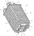
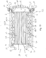
- a trained as exhaust heat exchanger 2 heat exchanger 1 is used for cooling exhaust gas by means of cooling liquid.
- the exhaust gas heat exchanger 2 has a first flow channel 12 for passing a first fluid, namely exhaust gas.
- a second flow channel 13 for passing a second fluid, namely cooling liquid, serves to transfer heat from the exhaust gas to the cooling liquid and thereby to cool the exhaust gas ( Fig. 13 ).
- the exhaust gas heat exchanger 2 is used in an arrangement, not shown for recycling and cooling of exhaust gas of an internal combustion engine to cool the exhaust gas from the engine by means of coolant of the engine and then fed again after cooling in the exhaust heat exchanger 2 a charge air duct, not shown for further combustion in a combustion chamber of the internal combustion engine.
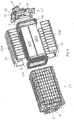
- the exhaust gas heat exchanger 2 comprises a housing 3 with a housing pot 4 and a housing cover 5 (FIG. Fig. 1 to 3 and 13 ).
- the housing 3, ie the housing pot 4 and the housing cover 5 are made of plastic and are produced by injection molding in a simple and inexpensive manner, because the housing 3 comprises only two components, namely the housing pot 4 and the housing cover 5.
- the housing 3 has housing ribs 38 on the outside.
- the housing ribs 38 serve on the one hand for the mechanical or static stiffening of the housing 3 and on the other hand to enlarge the surface of the housing 3 and thereby be able to deliver more heat to the environment of the exhaust gas heat exchanger 2.
- On the housing cover 5 are two inlet connection 31 ( Fig. 2 and 3 ) educated.
- the inlet pipe 31 thus flows through two inlet openings 15, the exhaust gas into the first flow channel 12 a.
- the exhaust gas flows from an outlet opening 16 (FIG. Fig. 1 to 3 and 13 ) again, which is thereby formed by an outlet 32.
- the housing cover 5 also has a sealing flange 34 (FIG. Fig. 3 and 13 ) on.
- the exhaust gas thus flows through the exhaust gas heat exchanger 2 in Fig. 13 from right to left.
- the two inlet openings 15 are due to the formation of cut in Fig. 13 not shown.
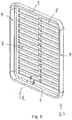
- a plurality of tubes 10 designed as flat tubes 11 are arranged in openings 8 of a first bottom 6 and a second bottom 7 (FIG. Fig. 11 and 13 ).
- the first and second floor 6, 7 further comprises a peripheral board 9 ( Fig. 6 and 10 ).
- the tubes 10 and the two plates 6, 7 are made of metal, in particular aluminum or stainless steel, and are materially connected, in particular by means of soldering, together.
- the formation of the flat tubes 11 and the two plates 6, 7 made of metal is required because through the flat tubes 11, the exhaust gas at very high temperatures, for example in the range of 600 ° to 800 ° C, is passed.
- FIG. Fig. 1 An inlet opening 17 for cooling liquid and an outlet opening 18 for cooling liquid (FIG. Fig. 1 ) educated.
- a cooling liquid line 35 ( Fig. 11 ) on.
- the cooling liquid is introduced into the interior of the housing 3.
- the introduction takes place to the effect that the exhaust gas heat exchanger 3 is a countercurrent cooler, ie, the cooling liquid flows through the exhaust gas heat exchanger 2 in an opposite direction than the exhaust gas.
- the heat exchanger 1 may also be a DC heat exchanger 1, ie, the first and second fluid flow through the heat exchanger 1 in the same direction.
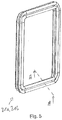
- first and second bottom 6, 7 On the board 9 of the first and second bottom 6, 7 is an elastic, consisting of plastic first and second seal 21a, 21b, respectively.
- first seal 21a and on the board 9 of the second bottom 7, the second seal 21b is arranged.
- the approximately U-shaped in cross-section seal 21a, 21b has five thickened portions 22 and four webs 23 ( FIGS. 8 and 10 ).
- the seals 21a, 21b rest on the compaction 22 on the board 9 and the first and second floor ( Fig. 10 ), so that form at the bearing surfaces of the thickenings 22 between the seal 21 a, 21 b and the board 9 and the first and second bottom 6, 7 sealing surfaces.
- a first groove 19 is present on the housing pot 4 and further on the housing 3, a first groove 19 is present.
- the first groove 19 forms to the effect that due to the geometry of the sealing flange 34 of the housing cover 5 and the housing pot 4, the first groove 19 is formed ( Fig. 13 ).
- the first groove 19 thus forms between the housing pot 4 and the housing cover 5.
- the board 9 of the first floor 6 with the first seal 21a is within the first groove 19 (FIG. Fig. 14 ) arranged. This results in a manner analogous to the sealing surfaces between the thickenings 22 and the first bottom 9 and sealing surfaces between the thickenings 22 and the housing 3, which is formed or limited in the region of the first groove 19 of the housing pot 4 and the housing cover 5. Chambers 24 thereby also form a drainage channel 26.
- cooling fluid as leakage fluid penetrates part of the sealing surfaces between seal 21a and the first floor 6 or the housing 3 fluid can flow from the chamber 24 or the drainage channel 26 through drainage openings 25 in the seal 21a, 21b from one chamber 24 into another chamber 24.
- the chamber arranged on the outside in the region of the housing 24 as a drainage channel 26 stands in connection with a desired outflow opening 27 of the housing 3.
- the housing 3 has, within or on the drainage channel 26, a multiplicity of desired outflow openings 27.
- the board 9 of the second bottom 7 is arranged in an analogous manner to the first bottom 6 in the second groove 20 of the housing 3, ie the housing pot 4.
- the sealing takes place in an analogous manner to the sealing of the rim 9 in the first groove 19.
- the housing pot 4 also has a plurality of Söllaushnetechnikö réelleen 27 and the seal 21b drainage openings 25 (FIGS. Fig. 15 ).
- an expansion gap 40 are each provided between the housing 3 and the first bottom 6 and the second bottom 7, an expansion gap 40 are each provided.
- the expansion gaps 40 allow strains of the metal flat tubes 11 and the two floors 6, 7 are compensated with respect to the housing 3 made of plastic.
- different, in particular temperature-induced strains between the housing 3 and the tubes 10 can be compensated in a simple manner.
- the exhaust gas heat exchanger 2 further comprises a flow straightener 28 made of plastic ( Fig. 2 to 4 . 11 and 13 ).
- the flow straightener 28 comprises an upper half shell 29 and a lower half shell 30.
- the flow straightener 28 has flow direction ribs 39 on the inside as well as on the outside.
- the upper half-shell 29 is by means of a tongue and groove connection ( FIGS. 11 and 12 ) is connected to the lower half-shell 30.
- the flow straightener 28 can thus be manufactured in a simple and inexpensive manner, for example by means of injection molding, with only two parts made of plastic.
- the flow straightener 28 serves to conduct the cooling liquid in the second flow channel correspondingly that the highest possible heat transfer from the exhaust gas to the cooling liquid is possible. This is made possible by the flow straightener 28 through the flow straightener ribs 39.
- the flow straightener 28 also has openings 33.
- the openings 33 serve to ensure that the cooling liquid flows through the flow straightener 28 in the section Fig. 11 can flow through each of the openings 33 both from top to bottom and from bottom to top.
- By means of the flow straightener ribs 39 is thereby achieved as uniform, in particular turbulent, flow around the flat tubes 11 by means of the cooling liquid.
- the production and installation of the exhaust gas heat exchanger 2 is particularly simple.
- the flat tubes 11 are initially only in the openings 8 of the first and second bottom 6, 7 to be arranged and then to connect in a soldering furnace cohesively by soldering.
- the housing pot 4, the housing cover 5 and the two half-shells 29 and 30 of the flow straightener 28 can thereby in a simple manner.
- Injection molding can be made by plastic. This also applies analogously to the two seals 21a and 21b. After soldering the flat tubes 11 to the two floors 6, 7, only the two seals 21a and 21b need to be pushed onto the shelf 9 of the first and second floor 6, 7 (FIG. Fig. 7 and 10 ).
- the two half-shells 29, 30 are pushed onto the flat tubes 11 and the two bottoms 6, 7 and connected to each other by means of the tongue and groove joint 36.
- the flow straightener 28 is clamped between the two floors 6, 7, so that then the interconnected components of the Abgastageübertragers 2, namely the flat tubes 11, the two floors 6, 7, the two seals 21 a, 21 b and the two half shells 29, 30th of the flow straightener 28 are simply inserted into the housing pot 4 of the housing 3.
- the housing cover 5 by means of a screw 37 ( Fig. 13 and 14 ) attached to the housing pot 4.
- the exhaust gas heat exchanger 2 can be attached to a motor vehicle or to an arrangement for returning and cooling exhaust gas of an internal combustion engine (not shown). Repair and maintenance work on the exhaust heat exchanger 2 at any time easily possible, because this only the screw 37 are open and then in a simple manner from the housing pot 4 after removing the housing cover 5 of the flow straightener 8 and the flat tubes 11 with the two floors 6, 7 can be taken out.
- the exhaust gas or charge air heat exchanger 1 according to the invention and the arrangement according to the invention for the return and cooling of exhaust gas of an internal combustion engine.
- the heat exchanger 1 only the flat tubes 11 and the two plates 6, 7 are made of aluminum and connected to one another in a material-locking manner.
- the other components of the heat exchanger 1 are made particularly simple and inexpensive by injection molding of plastic.
- the number of components of the heat exchanger 1 is small, for example, the housing 3 comprises only the housing pot 4 and the housing cover 5.
- the inlet and outlet openings 15, 16 for the exhaust gas and the housing 3 is already advantageously on the injection molded housing Inlet and outlet openings 17, 18 formed for the cooling liquid with.
- the heat exchanger 1 is thus inexpensive to manufacture and enables reliable and safe operation.
Landscapes
- Engineering & Computer Science (AREA)
- Mechanical Engineering (AREA)
- General Engineering & Computer Science (AREA)
- Physics & Mathematics (AREA)
- Thermal Sciences (AREA)
- Chemical & Material Sciences (AREA)
- Combustion & Propulsion (AREA)
- Heat-Exchange Devices With Radiators And Conduit Assemblies (AREA)
- Exhaust-Gas Circulating Devices (AREA)
Claims (12)
- Echangeur de chaleur (2) de gaz d'échappement ou d'air de suralimentation, ledit échangeur de chaleur comprenant :- un carter (3),- un premier et un second fond (6, 7) comportant des ouvertures (8),- des tubes (10) servant de premier conduit d'écoulement (12) pour la circulation d'un premier fluide, tubes dont les extrémités sont disposées dans les ouvertures (8) du premier et du second fond (6, 7),où les tubes (10) et le premier et le second fond (6, 7) sont disposés à l'intérieur du carter (3), de sorte qu'il se forme, entre le carter (3) et les tubes (10), un second conduit d'écoulement (13) servant à la circulation d'un second fluide tel qu'un liquide de refroidissement,
où au moins un interstice de dilatation (40) est formé entre le premier et / ou le second fond (6, 7) et le carter (3), pour compenser différentes dilatations se produisant entre le carter (3) et les tubes (10), et le carter (3) se compose en totalité de matière plastique et le carter (3) en matière plastique présente au moins une ouverture d'entrée et de sortie (15, 16) pour le premier fluide et au moins une ouverture d'entrée et de sortie (17, 18) pour le second fluide, et les tubes (10) et le premier et le second fond (6, 7) sont en totalité en métal, en particulier en aluminium, et les tubes (10) et le premier et le second fond (6, 7) sont assemblés les uns aux autres, par continuité de matière, en procédant par brasage, et le carter (10) est en deux parties, comprenant un pot de carter (4) et un couvercle de carter (5), où le premier et / ou le second fond (6, 7) présentent un bord circulaire (9), caractérisé en ce que le bord (9) est orienté pratiquement de façon parallèle à un axe des tubes (10), de sorte que le bord (9) forme, en direction de l'axe, une extrémité du premier et / ou du second fond (6, 7), et où le carter (3) présente, côté intérieur, une première et une seconde rainure circulaire (19, 20). - Echangeur de chaleur de gaz d'échappement ou d'air de suralimentation selon la revendication 1, caractérisé en ce que le bord (9) du premier fond (6) est disposé dans la première rainure (19), et le bord (9) du second fond (7) est disposé dans la seconde rainure (20).
- Echangeur de chaleur de gaz d'échappement ou d'air de suralimentation selon la revendication 2, caractérisé en ce qu'un premier joint d'étanchéité (21a) est disposé au niveau du bord (9) du premier fond (6), de sorte que le premier joint d'étanchéité (21a) est en contact, au niveau de la première rainure (19), avec le bord (9) du premier fond (6) et avec le carter (3).
- Echangeur de chaleur de gaz d'échappement ou d'air de suralimentation selon la revendication 2 ou 3, caractérisé en ce qu'un second joint d'étanchéité (21b) est disposé au niveau du bord (9) du second fond (7), de sorte que le second joint d'étanchéité (21b) est en contact, au niveau de la seconde rainure (20), avec le bord (9) du second fond (7) et avec le carter (3).
- Echangeur de chaleur de gaz d'échappement ou d'air de suralimentation selon la revendication 3 ou 4, caractérisé en ce que le premier et / ou le second joint d'étanchéité (21a, 21b) présente au moins deux, de préférence cinq épaississements (22) qui sont reliés les uns aux autres au moyen au moins d'une partie rétrécie (23), de préférence au moyen de trois parties rétrécies (23).
- Echangeur de chaleur de gaz d'échappement ou d'air de suralimentation selon l'une quelconque ou plusieurs des revendications 3 à 5, caractérisé en ce que le premier et / ou le second joint d'étanchéité (21a, 21b) entoure au moins en partie, en particulier en totalité, le bord (9) du premier et / ou du second fond (6, 7).
- Echangeur de chaleur de gaz d'échappement ou d'air de suralimentation selon l'une quelconque ou plusieurs des revendications 3 à 6, caractérisé en ce qu'au moins une chambre (24) est formée entre le premier et / ou le second joint d'étanchéité (21a, 21b) et le bord (9) et / ou en ce qu'au moins une chambre (24) est formée entre le premier et / ou le second joint d'étanchéité (21a, 21b) et le carter (3), au niveau de la première et / ou de la seconde rainure (19, 20) et / ou en ce que le premier et / ou le second joint d'étanchéité (21a, 21b) présente au moins une ouverture de drainage (25).
- Echangeur de chaleur de gaz d'échappement ou d'air de suralimentation selon l'une quelconque ou plusieurs des revendications précédentes, caractérisé en ce que le carter (3) présente un conduit de drainage (26) et / ou au moins une ouverture de sortie prévue (27), pour évacuer vers l'extérieur le premier et / ou le second fluide, en cas de fuites se produisant entre le premier et le second conduit d'écoulement (12, 13), et en particulier le conduit de drainage (26) et / ou l'ouverture de sortie prévue (27) débouchent dans la chambre (24) au moins au nombre de un.
- Echangeur de chaleur de gaz d'échappement ou d'air de suralimentation selon l'une quelconque ou plusieurs des revendications 1 à 8, caractérisé en ce qu'un interstice de dilatation (40) situé à l'extérieur du bord (9) et du carter (3) est formé entre le premier et / ou le second fond (6, 7) et / ou en ce qu'un interstice de dilatation (40) est formé entre l'extrémité du bord (9) du premier et / ou du second fond (6, 7) et le carter (3), et en ce que le joint d'étanchéité (21a, 21b) est disposé dans l'interstice de dilatation (40).
- Echangeur de chaleur de gaz d'échappement ou d'air de suralimentation selon l'une quelconque ou plusieurs des revendications précédentes, caractérisé en ce qu'un redresseur de flux (28) est disposé entre le carter (3) et les tubes (10).
- Echangeur de chaleur de gaz d'échappement ou d'air de suralimentation selon la revendication 10, caractérisé en ce que le redresseur de flux (28) est en deux parties, en particulier comprend deux demi-coques (29, 30), et le redresseur de flux (28) se compose de préférence au moins en partie, en particulier en totalité, de matière plastique.
- Agencement pour le recyclage et le refroidissement de gaz d'échappement d'un moteur à combustion interne, en particulier d'un moteur diesel, ledit agencement comprenant :- une conduite de gaz d'échappement, comprenant de préférence une turbine à gaz d'échappement,- une conduite d'air de suralimentation comprenant un compresseur d'air de suralimentation pouvant être entraîné de préférence par la turbine à gaz d'échappement,- une conduite de recyclage des gaz d'échappement servant à l'acheminement des gaz d'échappement depuis la conduite de gaz d'échappement jusqu'à la conduite d'air de suralimentation,- un échangeur de chaleur de gaz d'échappement servant au refroidissement des gaz d'échappement dans la conduite de recyclage des gaz d'échappement et / ou comprenant un échangeur de chaleur d'air de suralimentation servant au refroidissement de l'air de suralimentation dans la conduite d'air de suralimentation, ledit refroidissement se produisant dans la direction d'écoulement de l'air en aval du compresseur d'air de suralimentation,- de préférence un organe de commande de gaz d'échappement servant à la commande et / ou à la régulation de la quantité de gaz d'échappement pouvant être fournie, par unité de temps, par la conduite de recyclage des gaz d'échappement et / ou de préférence un organe de commande d'air de suralimentation servant à la commande et / ou à la régulation de la quantité d'air de suralimentation pouvant être fournie, par unité de temps, par la conduite d'air de suralimentation,caractérisé en ce que l'échangeur de chaleur de gaz d'échappement et / ou l'échangeur de chaleur d'air de suralimentation est conçu comme un échangeur de chaleur selon l'une quelconque ou plusieurs des revendications précédentes.
Applications Claiming Priority (1)
| Application Number | Priority Date | Filing Date | Title |
|---|---|---|---|
| DE102009043264A DE102009043264A1 (de) | 2009-09-29 | 2009-09-29 | Wärmeübertrager |
Publications (3)
| Publication Number | Publication Date |
|---|---|
| EP2302183A2 EP2302183A2 (fr) | 2011-03-30 |
| EP2302183A3 EP2302183A3 (fr) | 2014-08-06 |
| EP2302183B1 true EP2302183B1 (fr) | 2019-01-16 |
Family
ID=43414058
Family Applications (1)
| Application Number | Title | Priority Date | Filing Date |
|---|---|---|---|
| EP10179392.5A Not-in-force EP2302183B1 (fr) | 2009-09-29 | 2010-09-24 | Echangeur de chaleur pour gaz d'échappement ou pour air suralimenté |
Country Status (2)
| Country | Link |
|---|---|
| EP (1) | EP2302183B1 (fr) |
| DE (1) | DE102009043264A1 (fr) |
Families Citing this family (14)
| Publication number | Priority date | Publication date | Assignee | Title |
|---|---|---|---|---|
| DE102011080474A1 (de) | 2011-08-05 | 2013-02-07 | Behr Gmbh & Co. Kg | Wärmetauscheranordnung |
| DE102011053421A1 (de) * | 2011-09-09 | 2013-03-14 | Pierburg Gmbh | Vorprodukt eines Gehäuseteils, Innengehäuse, Wärmeübertragungsvorrichtung und Verfahren zur Herstellung eines derartigen Innengehäuses und einer derartigen Wärmeübertragungsvorrichtung |
| US9145858B2 (en) | 2012-02-29 | 2015-09-29 | Ford Global Technologies, Llc | Intake system with an integrated charge air cooler |
| DE102012204121A1 (de) * | 2012-03-15 | 2013-09-19 | Mahle International Gmbh | Ladeluftkühleinrichtung |
| DE102012214480A1 (de) | 2012-06-13 | 2013-12-19 | Eberspächer Climate Control Systems GmbH & Co. KG | Wärmetauscheranordnung |
| DE102013202056A1 (de) * | 2013-02-07 | 2014-08-07 | Mahle International Gmbh | Frischluftversorgungseinrichtung einer Brennkraftmaschine |
| DE102013202118A1 (de) * | 2013-02-08 | 2014-08-14 | Mahle International Gmbh | Frischluftanlage |
| DE102013008773B4 (de) * | 2013-05-23 | 2020-06-10 | Modine Manufacturing Company | Wärmetauscher und Verfahren zur Herstellung eines Wärmetauschers |
| JP6123484B2 (ja) | 2013-05-24 | 2017-05-10 | 株式会社デンソー | 冷媒蒸発器 |
| DE102013221151A1 (de) * | 2013-10-17 | 2015-04-23 | MAHLE Behr GmbH & Co. KG | Wärmeübertrager |
| EP3296535B1 (fr) * | 2016-09-14 | 2020-02-12 | Mahle International GmbH | Dispositif de refroidissement, notamment pour un véhicule automobile |
| DE102016011254A1 (de) | 2016-09-20 | 2018-03-22 | Modine Manufacturing Company | Bypass-Blockiervorrichtung für Wärmeübertrager |
| DE102017216819B4 (de) * | 2017-09-22 | 2021-03-11 | Hanon Systems | Abgaskühler und Abgasrückführsystem mit einem Abgaskühler |
| CN114739201B (zh) * | 2022-04-06 | 2024-04-09 | 浙江吉利控股集团有限公司 | 一种车辆的换热器总成及车辆 |
Citations (1)
| Publication number | Priority date | Publication date | Assignee | Title |
|---|---|---|---|---|
| WO2009068480A1 (fr) * | 2007-11-27 | 2009-06-04 | Valeo Termico S.A. | Echangeur de chaleur pour gaz, notamment pour les gaz d'echappement d'un moteur |
Family Cites Families (12)
| Publication number | Priority date | Publication date | Assignee | Title |
|---|---|---|---|---|
| US2512748A (en) * | 1945-02-12 | 1950-06-27 | Worthington Pump & Mach Corp | Expansion joint for heat exchangers |
| DE1812560A1 (de) * | 1968-12-04 | 1970-06-18 | Steinmueller Gmbh L & C | Waermeuebertrager mit beweglichen Rohrboeden,insbesondere einflutige Gegenstrom- oder Kreuzgegenstrom-Waermeuebertrager |
| US3548929A (en) * | 1969-10-03 | 1970-12-22 | Frank R Gross | Heat-transfer apparatus |
| DE3435093A1 (de) * | 1984-09-25 | 1986-04-03 | Süddeutsche Kühlerfabrik Julius Fr. Behr GmbH & Co KG, 7000 Stuttgart | Waermetauscher mit einem in einem gehaeuse angeordneten rohrbuendel |
| JPH06257975A (ja) * | 1993-03-08 | 1994-09-16 | Mitsubishi Electric Corp | 熱交換装置およびその放熱体 |
| DE29504526U1 (de) * | 1995-03-16 | 1996-07-18 | Autokühler GmbH & Co KG, 34369 Hofgeismar | Wärmeaustauscher, insbesondere für Kraftfahrzeuge |
| DE10218521A1 (de) | 2002-04-25 | 2003-11-06 | Behr Gmbh & Co | Abgaswärmeübertrager, insbesondere für Kraftfahrzeuge |
| DE10218729B4 (de) | 2002-04-26 | 2004-05-27 | Andawari Gmbh | Verfahren zum Authentifizieren und/oder Autorisieren von Personen |
| DE102004005518A1 (de) * | 2004-02-04 | 2005-09-01 | Meta Motoren- Und Energie-Technik Gmbh | Verfahren zum Steuern des Betriebes einer aufgeladenen Kolbenbrennkraftmaschine sowie Kolbenbrennkraftmaschine |
| DE102006051000A1 (de) * | 2005-10-26 | 2007-07-12 | Behr Gmbh & Co. Kg | Wärmetauscher, Verfahren zur Herstellung eines Wärmetauschers |
| DE102007010474A1 (de) | 2007-01-23 | 2008-07-24 | Behr Gmbh & Co. Kg | Wärmetauscher |
| DE102008002746A1 (de) * | 2007-07-11 | 2009-02-12 | Visteon Global Technologies Inc., Van Buren | Wärmetauscher für den Abgasstrang eines Kraftfahrzeugs, Verfahren zur Herstellung eines Wärmetauschers sowie Montagewerkzeug hierzu |
-
2009
- 2009-09-29 DE DE102009043264A patent/DE102009043264A1/de not_active Withdrawn
-
2010
- 2010-09-24 EP EP10179392.5A patent/EP2302183B1/fr not_active Not-in-force
Patent Citations (1)
| Publication number | Priority date | Publication date | Assignee | Title |
|---|---|---|---|---|
| WO2009068480A1 (fr) * | 2007-11-27 | 2009-06-04 | Valeo Termico S.A. | Echangeur de chaleur pour gaz, notamment pour les gaz d'echappement d'un moteur |
Also Published As
| Publication number | Publication date |
|---|---|
| EP2302183A3 (fr) | 2014-08-06 |
| DE102009043264A1 (de) | 2011-03-31 |
| EP2302183A2 (fr) | 2011-03-30 |
Similar Documents
| Publication | Publication Date | Title |
|---|---|---|
| EP2302183B1 (fr) | Echangeur de chaleur pour gaz d'échappement ou pour air suralimenté | |
| EP2715086B1 (fr) | Échangeur de chaleur | |
| EP1999423B1 (fr) | Refroidisseur de gaz d'echappement pour véhicule automobile | |
| EP3169964B1 (fr) | Échangeur de chaleur | |
| EP1682767A1 (fr) | Echangeur de chaleur | |
| EP1996892A2 (fr) | Echangeur de chaleur et procede de fabrication d'un echangeur de chaleur | |
| DE102012000875B4 (de) | Saugrohr einer Brennkraftmaschine mit einem Kühlfluidladeluftkühler | |
| EP3723246A1 (fr) | Dispositif de contrôle de la température pour un module électrique et module électrique doté d'un tel dispositif | |
| EP3056847B1 (fr) | Dispositif et procede destines a la thermoregulation d'un corps | |
| EP2037201A2 (fr) | Module d'air de suralimentation pour un moteur à combustion interne | |
| DE102005037156A1 (de) | Wärmetauscher | |
| DE102007048824B4 (de) | Wärmetauscher, insbesondere zur Abgaskühlung | |
| DE102005045103B3 (de) | Kühlvorrichtung für eine Verbrennungskraftmaschine | |
| DE102011001461A1 (de) | Abgasrückführmodul für eine Verbrennungskraftmaschine | |
| DE102008056810A1 (de) | Kühlvorrichtung für eine Verbrennungskraftmaschine | |
| EP2444615A1 (fr) | Dispositif de transport de gaz d'échappement pour un moteur à combustion interne | |
| EP2886991B1 (fr) | Caloporteur | |
| EP2218897B1 (fr) | Dispositif de recirculation de gaz d'échappement pour un moteur à combustion interne | |
| DE102010009061B4 (de) | Anordnung einer Kühlvorrichtung in einer Verbrennungskraftmaschine | |
| DE102016010393B4 (de) | Anbindungsflansch einer fluidführenden Vorrichtung und fluidführende Vorrichtung mit wenigstens einem Anbindungsflansch | |
| DE102010001635A1 (de) | Wärmeübertrager | |
| DE102010007124B4 (de) | Wärmeübertragungsvorrichtung sowie Anordnung zur Abgasrückführung mit einer derartigen Wärmeübertragungsvorrichtung | |
| DE102016115526A1 (de) | Zylinderkurbelgehäuse für eine Brennkraftmaschine mit Kunststoffgehäuse und Metall-Insert | |
| DE102014222158A1 (de) | Abgaswärmeübertrager | |
| DE102009050888A1 (de) | Wärmeübertrager |
Legal Events
| Date | Code | Title | Description |
|---|---|---|---|
| PUAI | Public reference made under article 153(3) epc to a published international application that has entered the european phase |
Free format text: ORIGINAL CODE: 0009012 |
|
| AK | Designated contracting states |
Kind code of ref document: A2 Designated state(s): AL AT BE BG CH CY CZ DE DK EE ES FI FR GB GR HR HU IE IS IT LI LT LU LV MC MK MT NL NO PL PT RO SE SI SK SM TR |
|
| AX | Request for extension of the european patent |
Extension state: BA ME RS |
|
| PUAL | Search report despatched |
Free format text: ORIGINAL CODE: 0009013 |
|
| AK | Designated contracting states |
Kind code of ref document: A3 Designated state(s): AL AT BE BG CH CY CZ DE DK EE ES FI FR GB GR HR HU IE IS IT LI LT LU LV MC MK MT NL NO PL PT RO SE SI SK SM TR |
|
| AX | Request for extension of the european patent |
Extension state: BA ME RS |
|
| RIC1 | Information provided on ipc code assigned before grant |
Ipc: F28F 9/02 20060101ALI20140630BHEP Ipc: F28F 9/00 20060101ALI20140630BHEP Ipc: F02B 29/04 20060101AFI20140630BHEP Ipc: F28D 21/00 20060101ALI20140630BHEP Ipc: F28D 7/16 20060101ALI20140630BHEP Ipc: F02M 25/07 20060101ALI20140630BHEP |
|
| 17P | Request for examination filed |
Effective date: 20150206 |
|
| RBV | Designated contracting states (corrected) |
Designated state(s): AL AT BE BG CH CY CZ DE DK EE ES FI FR GB GR HR HU IE IS IT LI LT LU LV MC MK MT NL NO PL PT RO SE SI SK SM TR |
|
| RAP1 | Party data changed (applicant data changed or rights of an application transferred) |
Owner name: MAHLE BEHR GMBH & CO. KG |
|
| 17Q | First examination report despatched |
Effective date: 20160105 |
|
| STAA | Information on the status of an ep patent application or granted ep patent |
Free format text: STATUS: EXAMINATION IS IN PROGRESS |
|
| REG | Reference to a national code |
Ref country code: DE Ref legal event code: R079 Ref document number: 502010015736 Country of ref document: DE Free format text: PREVIOUS MAIN CLASS: F02B0029040000 Ipc: F02M0026320000 |
|
| GRAP | Despatch of communication of intention to grant a patent |
Free format text: ORIGINAL CODE: EPIDOSNIGR1 |
|
| STAA | Information on the status of an ep patent application or granted ep patent |
Free format text: STATUS: GRANT OF PATENT IS INTENDED |
|
| RIC1 | Information provided on ipc code assigned before grant |
Ipc: F28F 9/00 20060101ALI20180528BHEP Ipc: F02B 29/04 20060101ALI20180528BHEP Ipc: F28F 9/02 20060101ALI20180528BHEP Ipc: F28D 7/16 20060101ALI20180528BHEP Ipc: F02M 26/32 20160101AFI20180528BHEP Ipc: F28D 21/00 20060101ALI20180528BHEP |
|
| INTG | Intention to grant announced |
Effective date: 20180702 |
|
| GRAJ | Information related to disapproval of communication of intention to grant by the applicant or resumption of examination proceedings by the epo deleted |
Free format text: ORIGINAL CODE: EPIDOSDIGR1 |
|
| STAA | Information on the status of an ep patent application or granted ep patent |
Free format text: STATUS: EXAMINATION IS IN PROGRESS |
|
| GRAR | Information related to intention to grant a patent recorded |
Free format text: ORIGINAL CODE: EPIDOSNIGR71 |
|
| GRAS | Grant fee paid |
Free format text: ORIGINAL CODE: EPIDOSNIGR3 |
|
| STAA | Information on the status of an ep patent application or granted ep patent |
Free format text: STATUS: GRANT OF PATENT IS INTENDED |
|
| INTC | Intention to grant announced (deleted) | ||
| GRAA | (expected) grant |
Free format text: ORIGINAL CODE: 0009210 |
|
| STAA | Information on the status of an ep patent application or granted ep patent |
Free format text: STATUS: THE PATENT HAS BEEN GRANTED |
|
| AK | Designated contracting states |
Kind code of ref document: B1 Designated state(s): AL AT BE BG CH CY CZ DE DK EE ES FI FR GB GR HR HU IE IS IT LI LT LU LV MC MK MT NL NO PL PT RO SE SI SK SM TR |
|
| INTG | Intention to grant announced |
Effective date: 20181207 |
|
| REG | Reference to a national code |
Ref country code: GB Ref legal event code: FG4D Free format text: NOT ENGLISH |
|
| REG | Reference to a national code |
Ref country code: CH Ref legal event code: EP Ref country code: CH Ref legal event code: PK Free format text: BERICHTIGUNGEN |
|
| REG | Reference to a national code |
Ref country code: IE Ref legal event code: FG4D Free format text: LANGUAGE OF EP DOCUMENT: GERMAN |
|
| RIC2 | Information provided on ipc code assigned after grant |
Ipc: F28D 7/16 20060101ALI20180528BHEP Ipc: F02B 29/04 20060101ALI20180528BHEP Ipc: F28F 9/02 20060101ALI20180528BHEP Ipc: F28F 9/00 20060101ALI20180528BHEP Ipc: F28D 21/00 20060101ALI20180528BHEP Ipc: F02M 26/32 20160101AFI20180528BHEP |
|
| REG | Reference to a national code |
Ref country code: DE Ref legal event code: R096 Ref document number: 502010015736 Country of ref document: DE |
|
| REG | Reference to a national code |
Ref country code: AT Ref legal event code: REF Ref document number: 1089880 Country of ref document: AT Kind code of ref document: T Effective date: 20190215 |
|
| REG | Reference to a national code |
Ref country code: NL Ref legal event code: MP Effective date: 20190116 |
|
| REG | Reference to a national code |
Ref country code: LT Ref legal event code: MG4D |
|
| PG25 | Lapsed in a contracting state [announced via postgrant information from national office to epo] |
Ref country code: NL Free format text: LAPSE BECAUSE OF FAILURE TO SUBMIT A TRANSLATION OF THE DESCRIPTION OR TO PAY THE FEE WITHIN THE PRESCRIBED TIME-LIMIT Effective date: 20190116 |
|
| PG25 | Lapsed in a contracting state [announced via postgrant information from national office to epo] |
Ref country code: FI Free format text: LAPSE BECAUSE OF FAILURE TO SUBMIT A TRANSLATION OF THE DESCRIPTION OR TO PAY THE FEE WITHIN THE PRESCRIBED TIME-LIMIT Effective date: 20190116 Ref country code: LT Free format text: LAPSE BECAUSE OF FAILURE TO SUBMIT A TRANSLATION OF THE DESCRIPTION OR TO PAY THE FEE WITHIN THE PRESCRIBED TIME-LIMIT Effective date: 20190116 Ref country code: PT Free format text: LAPSE BECAUSE OF FAILURE TO SUBMIT A TRANSLATION OF THE DESCRIPTION OR TO PAY THE FEE WITHIN THE PRESCRIBED TIME-LIMIT Effective date: 20190516 Ref country code: ES Free format text: LAPSE BECAUSE OF FAILURE TO SUBMIT A TRANSLATION OF THE DESCRIPTION OR TO PAY THE FEE WITHIN THE PRESCRIBED TIME-LIMIT Effective date: 20190116 Ref country code: SE Free format text: LAPSE BECAUSE OF FAILURE TO SUBMIT A TRANSLATION OF THE DESCRIPTION OR TO PAY THE FEE WITHIN THE PRESCRIBED TIME-LIMIT Effective date: 20190116 Ref country code: PL Free format text: LAPSE BECAUSE OF FAILURE TO SUBMIT A TRANSLATION OF THE DESCRIPTION OR TO PAY THE FEE WITHIN THE PRESCRIBED TIME-LIMIT Effective date: 20190116 Ref country code: NO Free format text: LAPSE BECAUSE OF FAILURE TO SUBMIT A TRANSLATION OF THE DESCRIPTION OR TO PAY THE FEE WITHIN THE PRESCRIBED TIME-LIMIT Effective date: 20190416 |
|
| PG25 | Lapsed in a contracting state [announced via postgrant information from national office to epo] |
Ref country code: HR Free format text: LAPSE BECAUSE OF FAILURE TO SUBMIT A TRANSLATION OF THE DESCRIPTION OR TO PAY THE FEE WITHIN THE PRESCRIBED TIME-LIMIT Effective date: 20190116 Ref country code: IS Free format text: LAPSE BECAUSE OF FAILURE TO SUBMIT A TRANSLATION OF THE DESCRIPTION OR TO PAY THE FEE WITHIN THE PRESCRIBED TIME-LIMIT Effective date: 20190516 Ref country code: LV Free format text: LAPSE BECAUSE OF FAILURE TO SUBMIT A TRANSLATION OF THE DESCRIPTION OR TO PAY THE FEE WITHIN THE PRESCRIBED TIME-LIMIT Effective date: 20190116 Ref country code: GR Free format text: LAPSE BECAUSE OF FAILURE TO SUBMIT A TRANSLATION OF THE DESCRIPTION OR TO PAY THE FEE WITHIN THE PRESCRIBED TIME-LIMIT Effective date: 20190417 Ref country code: BG Free format text: LAPSE BECAUSE OF FAILURE TO SUBMIT A TRANSLATION OF THE DESCRIPTION OR TO PAY THE FEE WITHIN THE PRESCRIBED TIME-LIMIT Effective date: 20190416 |
|
| REG | Reference to a national code |
Ref country code: DE Ref legal event code: R097 Ref document number: 502010015736 Country of ref document: DE |
|
| PG25 | Lapsed in a contracting state [announced via postgrant information from national office to epo] |
Ref country code: RO Free format text: LAPSE BECAUSE OF FAILURE TO SUBMIT A TRANSLATION OF THE DESCRIPTION OR TO PAY THE FEE WITHIN THE PRESCRIBED TIME-LIMIT Effective date: 20190116 Ref country code: IT Free format text: LAPSE BECAUSE OF FAILURE TO SUBMIT A TRANSLATION OF THE DESCRIPTION OR TO PAY THE FEE WITHIN THE PRESCRIBED TIME-LIMIT Effective date: 20190116 Ref country code: CZ Free format text: LAPSE BECAUSE OF FAILURE TO SUBMIT A TRANSLATION OF THE DESCRIPTION OR TO PAY THE FEE WITHIN THE PRESCRIBED TIME-LIMIT Effective date: 20190116 Ref country code: SK Free format text: LAPSE BECAUSE OF FAILURE TO SUBMIT A TRANSLATION OF THE DESCRIPTION OR TO PAY THE FEE WITHIN THE PRESCRIBED TIME-LIMIT Effective date: 20190116 Ref country code: AL Free format text: LAPSE BECAUSE OF FAILURE TO SUBMIT A TRANSLATION OF THE DESCRIPTION OR TO PAY THE FEE WITHIN THE PRESCRIBED TIME-LIMIT Effective date: 20190116 Ref country code: EE Free format text: LAPSE BECAUSE OF FAILURE TO SUBMIT A TRANSLATION OF THE DESCRIPTION OR TO PAY THE FEE WITHIN THE PRESCRIBED TIME-LIMIT Effective date: 20190116 Ref country code: DK Free format text: LAPSE BECAUSE OF FAILURE TO SUBMIT A TRANSLATION OF THE DESCRIPTION OR TO PAY THE FEE WITHIN THE PRESCRIBED TIME-LIMIT Effective date: 20190116 |
|
| PLBE | No opposition filed within time limit |
Free format text: ORIGINAL CODE: 0009261 |
|
| STAA | Information on the status of an ep patent application or granted ep patent |
Free format text: STATUS: NO OPPOSITION FILED WITHIN TIME LIMIT |
|
| PG25 | Lapsed in a contracting state [announced via postgrant information from national office to epo] |
Ref country code: SM Free format text: LAPSE BECAUSE OF FAILURE TO SUBMIT A TRANSLATION OF THE DESCRIPTION OR TO PAY THE FEE WITHIN THE PRESCRIBED TIME-LIMIT Effective date: 20190116 |
|
| 26N | No opposition filed |
Effective date: 20191017 |
|
| PG25 | Lapsed in a contracting state [announced via postgrant information from national office to epo] |
Ref country code: SI Free format text: LAPSE BECAUSE OF FAILURE TO SUBMIT A TRANSLATION OF THE DESCRIPTION OR TO PAY THE FEE WITHIN THE PRESCRIBED TIME-LIMIT Effective date: 20190116 |
|
| PG25 | Lapsed in a contracting state [announced via postgrant information from national office to epo] |
Ref country code: TR Free format text: LAPSE BECAUSE OF FAILURE TO SUBMIT A TRANSLATION OF THE DESCRIPTION OR TO PAY THE FEE WITHIN THE PRESCRIBED TIME-LIMIT Effective date: 20190116 |
|
| REG | Reference to a national code |
Ref country code: DE Ref legal event code: R119 Ref document number: 502010015736 Country of ref document: DE |
|
| PG25 | Lapsed in a contracting state [announced via postgrant information from national office to epo] |
Ref country code: MC Free format text: LAPSE BECAUSE OF FAILURE TO SUBMIT A TRANSLATION OF THE DESCRIPTION OR TO PAY THE FEE WITHIN THE PRESCRIBED TIME-LIMIT Effective date: 20190116 |
|
| REG | Reference to a national code |
Ref country code: CH Ref legal event code: PL |
|
| PG25 | Lapsed in a contracting state [announced via postgrant information from national office to epo] |
Ref country code: CH Free format text: LAPSE BECAUSE OF NON-PAYMENT OF DUE FEES Effective date: 20190930 Ref country code: IE Free format text: LAPSE BECAUSE OF NON-PAYMENT OF DUE FEES Effective date: 20190924 Ref country code: DE Free format text: LAPSE BECAUSE OF NON-PAYMENT OF DUE FEES Effective date: 20200401 Ref country code: LU Free format text: LAPSE BECAUSE OF NON-PAYMENT OF DUE FEES Effective date: 20190924 Ref country code: LI Free format text: LAPSE BECAUSE OF NON-PAYMENT OF DUE FEES Effective date: 20190930 |
|
| REG | Reference to a national code |
Ref country code: BE Ref legal event code: MM Effective date: 20190930 |
|
| PG25 | Lapsed in a contracting state [announced via postgrant information from national office to epo] |
Ref country code: BE Free format text: LAPSE BECAUSE OF NON-PAYMENT OF DUE FEES Effective date: 20190930 |
|
| GBPC | Gb: european patent ceased through non-payment of renewal fee |
Effective date: 20190924 |
|
| PG25 | Lapsed in a contracting state [announced via postgrant information from national office to epo] |
Ref country code: FR Free format text: LAPSE BECAUSE OF NON-PAYMENT OF DUE FEES Effective date: 20190930 Ref country code: GB Free format text: LAPSE BECAUSE OF NON-PAYMENT OF DUE FEES Effective date: 20190924 |
|
| REG | Reference to a national code |
Ref country code: AT Ref legal event code: MM01 Ref document number: 1089880 Country of ref document: AT Kind code of ref document: T Effective date: 20190924 |
|
| PG25 | Lapsed in a contracting state [announced via postgrant information from national office to epo] |
Ref country code: AT Free format text: LAPSE BECAUSE OF NON-PAYMENT OF DUE FEES Effective date: 20190924 |
|
| PG25 | Lapsed in a contracting state [announced via postgrant information from national office to epo] |
Ref country code: CY Free format text: LAPSE BECAUSE OF FAILURE TO SUBMIT A TRANSLATION OF THE DESCRIPTION OR TO PAY THE FEE WITHIN THE PRESCRIBED TIME-LIMIT Effective date: 20190116 |
|
| PG25 | Lapsed in a contracting state [announced via postgrant information from national office to epo] |
Ref country code: HU Free format text: LAPSE BECAUSE OF FAILURE TO SUBMIT A TRANSLATION OF THE DESCRIPTION OR TO PAY THE FEE WITHIN THE PRESCRIBED TIME-LIMIT; INVALID AB INITIO Effective date: 20100924 Ref country code: MT Free format text: LAPSE BECAUSE OF FAILURE TO SUBMIT A TRANSLATION OF THE DESCRIPTION OR TO PAY THE FEE WITHIN THE PRESCRIBED TIME-LIMIT Effective date: 20190116 |
|
| PG25 | Lapsed in a contracting state [announced via postgrant information from national office to epo] |
Ref country code: MK Free format text: LAPSE BECAUSE OF FAILURE TO SUBMIT A TRANSLATION OF THE DESCRIPTION OR TO PAY THE FEE WITHIN THE PRESCRIBED TIME-LIMIT Effective date: 20190116 |