EP2302186A2 - Appareil et procédé de commande de moteur - Google Patents
Appareil et procédé de commande de moteur Download PDFInfo
- Publication number
- EP2302186A2 EP2302186A2 EP10174061A EP10174061A EP2302186A2 EP 2302186 A2 EP2302186 A2 EP 2302186A2 EP 10174061 A EP10174061 A EP 10174061A EP 10174061 A EP10174061 A EP 10174061A EP 2302186 A2 EP2302186 A2 EP 2302186A2
- Authority
- EP
- European Patent Office
- Prior art keywords
- opening degree
- engine
- values
- vnt
- egr
- Prior art date
- Legal status (The legal status is an assumption and is not a legal conclusion. Google has not performed a legal analysis and makes no representation as to the accuracy of the status listed.)
- Granted
Links
Images


Classifications
-
- F—MECHANICAL ENGINEERING; LIGHTING; HEATING; WEAPONS; BLASTING
- F02—COMBUSTION ENGINES; HOT-GAS OR COMBUSTION-PRODUCT ENGINE PLANTS
- F02D—CONTROLLING COMBUSTION ENGINES
- F02D41/00—Electrical control of supply of combustible mixture or its constituents
- F02D41/0002—Controlling intake air
- F02D41/0007—Controlling intake air for control of turbo-charged or super-charged engines
-
- F—MECHANICAL ENGINEERING; LIGHTING; HEATING; WEAPONS; BLASTING
- F02—COMBUSTION ENGINES; HOT-GAS OR COMBUSTION-PRODUCT ENGINE PLANTS
- F02D—CONTROLLING COMBUSTION ENGINES
- F02D41/00—Electrical control of supply of combustible mixture or its constituents
- F02D41/0025—Controlling engines characterised by use of non-liquid fuels, pluralities of fuels, or non-fuel substances added to the combustible mixtures
- F02D41/0047—Controlling exhaust gas recirculation [EGR]
- F02D41/005—Controlling exhaust gas recirculation [EGR] according to engine operating conditions
- F02D41/0052—Feedback control of engine parameters, e.g. for control of air/fuel ratio or intake air amount
-
- F—MECHANICAL ENGINEERING; LIGHTING; HEATING; WEAPONS; BLASTING
- F02—COMBUSTION ENGINES; HOT-GAS OR COMBUSTION-PRODUCT ENGINE PLANTS
- F02D—CONTROLLING COMBUSTION ENGINES
- F02D41/00—Electrical control of supply of combustible mixture or its constituents
- F02D41/02—Circuit arrangements for generating control signals
- F02D41/04—Introducing corrections for particular operating conditions
- F02D41/10—Introducing corrections for particular operating conditions for acceleration
-
- F—MECHANICAL ENGINEERING; LIGHTING; HEATING; WEAPONS; BLASTING
- F02—COMBUSTION ENGINES; HOT-GAS OR COMBUSTION-PRODUCT ENGINE PLANTS
- F02D—CONTROLLING COMBUSTION ENGINES
- F02D41/00—Electrical control of supply of combustible mixture or its constituents
- F02D41/02—Circuit arrangements for generating control signals
- F02D41/18—Circuit arrangements for generating control signals by measuring intake air flow
-
- F—MECHANICAL ENGINEERING; LIGHTING; HEATING; WEAPONS; BLASTING
- F02—COMBUSTION ENGINES; HOT-GAS OR COMBUSTION-PRODUCT ENGINE PLANTS
- F02D—CONTROLLING COMBUSTION ENGINES
- F02D41/00—Electrical control of supply of combustible mixture or its constituents
- F02D41/02—Circuit arrangements for generating control signals
- F02D41/14—Introducing closed-loop corrections
- F02D41/1401—Introducing closed-loop corrections characterised by the control or regulation method
- F02D2041/1409—Introducing closed-loop corrections characterised by the control or regulation method using at least a proportional, integral or derivative controller
-
- F—MECHANICAL ENGINEERING; LIGHTING; HEATING; WEAPONS; BLASTING
- F02—COMBUSTION ENGINES; HOT-GAS OR COMBUSTION-PRODUCT ENGINE PLANTS
- F02D—CONTROLLING COMBUSTION ENGINES
- F02D41/00—Electrical control of supply of combustible mixture or its constituents
- F02D41/02—Circuit arrangements for generating control signals
- F02D41/14—Introducing closed-loop corrections
- F02D41/1401—Introducing closed-loop corrections characterised by the control or regulation method
- F02D2041/141—Introducing closed-loop corrections characterised by the control or regulation method using a feed-forward control element
-
- F—MECHANICAL ENGINEERING; LIGHTING; HEATING; WEAPONS; BLASTING
- F02—COMBUSTION ENGINES; HOT-GAS OR COMBUSTION-PRODUCT ENGINE PLANTS
- F02D—CONTROLLING COMBUSTION ENGINES
- F02D41/00—Electrical control of supply of combustible mixture or its constituents
- F02D41/02—Circuit arrangements for generating control signals
- F02D41/14—Introducing closed-loop corrections
- F02D41/1401—Introducing closed-loop corrections characterised by the control or regulation method
- F02D2041/1413—Controller structures or design
- F02D2041/1431—Controller structures or design the system including an input-output delay
-
- F—MECHANICAL ENGINEERING; LIGHTING; HEATING; WEAPONS; BLASTING
- F02—COMBUSTION ENGINES; HOT-GAS OR COMBUSTION-PRODUCT ENGINE PLANTS
- F02D—CONTROLLING COMBUSTION ENGINES
- F02D41/00—Electrical control of supply of combustible mixture or its constituents
- F02D41/02—Circuit arrangements for generating control signals
- F02D41/14—Introducing closed-loop corrections
- F02D41/1401—Introducing closed-loop corrections characterised by the control or regulation method
- F02D2041/1433—Introducing closed-loop corrections characterised by the control or regulation method using a model or simulation of the system
-
- F—MECHANICAL ENGINEERING; LIGHTING; HEATING; WEAPONS; BLASTING
- F02—COMBUSTION ENGINES; HOT-GAS OR COMBUSTION-PRODUCT ENGINE PLANTS
- F02D—CONTROLLING COMBUSTION ENGINES
- F02D2200/00—Input parameters for engine control
- F02D2200/02—Input parameters for engine control the parameters being related to the engine
- F02D2200/04—Engine intake system parameters
- F02D2200/0406—Intake manifold pressure
-
- Y—GENERAL TAGGING OF NEW TECHNOLOGICAL DEVELOPMENTS; GENERAL TAGGING OF CROSS-SECTIONAL TECHNOLOGIES SPANNING OVER SEVERAL SECTIONS OF THE IPC; TECHNICAL SUBJECTS COVERED BY FORMER USPC CROSS-REFERENCE ART COLLECTIONS [XRACs] AND DIGESTS
- Y02—TECHNOLOGIES OR APPLICATIONS FOR MITIGATION OR ADAPTATION AGAINST CLIMATE CHANGE
- Y02T—CLIMATE CHANGE MITIGATION TECHNOLOGIES RELATED TO TRANSPORTATION
- Y02T10/00—Road transport of goods or passengers
- Y02T10/10—Internal combustion engine [ICE] based vehicles
- Y02T10/12—Improving ICE efficiencies
-
- Y—GENERAL TAGGING OF NEW TECHNOLOGICAL DEVELOPMENTS; GENERAL TAGGING OF CROSS-SECTIONAL TECHNOLOGIES SPANNING OVER SEVERAL SECTIONS OF THE IPC; TECHNICAL SUBJECTS COVERED BY FORMER USPC CROSS-REFERENCE ART COLLECTIONS [XRACs] AND DIGESTS
- Y02—TECHNOLOGIES OR APPLICATIONS FOR MITIGATION OR ADAPTATION AGAINST CLIMATE CHANGE
- Y02T—CLIMATE CHANGE MITIGATION TECHNOLOGIES RELATED TO TRANSPORTATION
- Y02T10/00—Road transport of goods or passengers
- Y02T10/10—Internal combustion engine [ICE] based vehicles
- Y02T10/40—Engine management systems
Definitions
- This technique relates to a control technique of an engine.
- the Mass Air Flow (MAF) and Manifold Air Pressure (MAP) are controlled optimally by an intake gas control system.
- MAF Mass Air Flow
- MAP Manifold Air Pressure
- the intake gas control system of the diesel engine includes a MAP control system and MAF control system, and MAP and MAF are independently controlled each other.
- the MAP control system controls a nozzle diameter of a Variable Nozzle Turbo (VNT) to control the MAP.
- VNT Variable Nozzle Turbo
- the MAF control system controls a valve opening degree of an Exhaust Gas Recirculator (EGR) that recirculates the exhaust gas into a cylinder to control MAF.
- EGR Exhaust Gas Recirculator
- the delay of the response occurs in the transient state in which the target value itself changes.
- the MAP instantaneously changes from the state A to the state B and the disturbance suppression is carried out during the change.
- a dynamic characteristic such as the first-order time-lag, exists in a series of processes that the turbo engine speed increases by the increase of the exhaust gas pressure and the MAP finally increases.
- a conventional technique exists that the engine response is optimized by controlling an exhaust turbine supercharger during the transient time of an accelerator opening degree.
- a variable nozzle basic opening signal and a feed-forward term signal which are calculated and outputted according to a variable nozzle opening basic map and a transient map for calculating the feed-forward term of the exhaust turbine supercharger by using the engine speed and the fuel injection quantity, are confluent at a confluent circuit.
- the opening degree of the variable nozzle is held at the value before transition of the accelerator opening degree by a variable nozzle throttling delay time computing circuit using the confluent signal and an accelerator opening transient signal, and the exhaust turbine supercharger is controlled so that the optimized engine response can be achieved by delaying throttling of the variable nozzle by using a variable nozzle throttling delay signal at the transient time of the accelerator opening degree.
- a valve opening degree of the EGR is not considered.
- a conventional technique exists for a supercharged engine with an EGR device having an EGR rate feedback control system and a MAP feedback system and capable of reducing NOx and smoke in exhaust gas by conducting suitable EGR even when an engine operating state is in a transient state.
- the EGR rate feedback control system in the conventional technique calculates a target EGR rate from an engine speed, basic injection quantity of the fuel and map data, carries out PI control by using a difference between a measurement value and a calculated value, calculates basic EGR valve lift from the engine speed, the basic injection quantity of the fuel and another map data, and calculates a target EGR valve lift by adding the basic EGR valve lift to a result value of the PI control.
- the MAP feedback system calculates a target MAP from the engine speed, the basic injection quantity f the fuel and the map data, carries out the PI control by using the difference between the target MP and a measurement value of a MAP sensor, calculates a basic VNT lift from the engine speed, the basic injection quantity of the fuel and another map data, and calculates a target VNT lift by adding the basic VNT lift to a result value of the PI control.
- the map data to calculate the basic EGR valve lift and the map data to calculate the basic VNT lift are not disclosed in detail, and it is unclear what value is calculated.
- an engine control method includes:
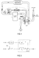
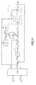
- FIG. 1 depicts an outline of a diesel engine as an engine relating to an embodiment of the invention.
- An Exhaust Gas Recirculator EGR to provide exhaust gas from an engine body 1 and a Variable Nozzle Turbo VNT to compress and provide fresh air to the engine body 1 by rotating a turbine by the pressure of the exhaust gas are coupled to the engine body 1.
- a nozzle opening degree of the VNT By adjusting a nozzle opening degree of the VNT, the rotation of the turbine of the VNT are adjusted, and a Manifold Air Pressure (MAP) measured by a MAP sensor is adjusted.
- MAP Manifold Air Pressure
- MAF Mass Air Flow
- a conventional control system for such an engine is depicted by a block diagram as depicted in FIG. 2 .
- a difference Xerr between Xref and a combination X of the measurement values of the MAF and MAP is inputted to a controller 12, and the controller 12 calculates a combination Ufb of feedback control values of the EGR valve opening degree and the VNT nozzle opening degree.
- a command value U which is a sum of Uref and Ufb, is calculated, and the command value U is inputted to a transfer function Gpn of a steady-state characteristic model of the engine body 1.
- a desired characteristic Gd is realized by compensating the transient response characteristic of the engine 1.
- Gd is represented by a first-order time-lag system having a certain time constant. The lesser the time constant is, the better the response becomes. However, because the control system may be unstable due to the influence of the noise or the like, an appropriate value is used for the time constant.
- FIG. 5 depicts an entire control system. Namely, in the entire control system, the setting values of the injection quantity Q and the engine speed RPM are inputted, and Uref and Xref, which correspond to the setting values of the injection quantity Q and engine speed RPM, are read out from the table 11 depicted in FIG. 2 . Then, a difference Xerr between Xref and the combination X of the measurement values of MAF and MAP is inputted to the controller 12, and the controller 12 calculates the combination Ufb of the feedback control values of the EGR valve opening degree and the VNT nozzle opening degree.
- a new command value U is calculated by further adding Uff, which is a result obtained by operating the newly introduced transfer function F to the injection quantity Q, to the sum of Uref and Ufb.
- the command value U is inputted into the transfer function Gpn of the steady-state characteristic model of the engine body 1.
- ⁇ X is obtained by operating Gpn to U.
- the setting value of the injection quantity Q is inputted to the transfer function Gpq of the transient response characteristic model of the engine body 1.
- Xq is obtained by operating Gpq to Q.
- the transfer function F to be set is identified from the transfer function Gd of the desired characteristic, the transfer function Gpq of the transient response characteristic of the engine body 1 and the transfer function Gpn of the steady-state characteristic of the engine body 1.
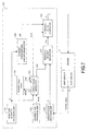
- FIG. 5 is converted to FIG. 6 .
- the setting values of the injection quantity Q and the engine speed RPM are inputted, and Uref and Xref, which correspond to the setting values of the injection quantity Q and the engine speed RPM, are read out from the same table 11 as a table in FIG. 2 .
- the difference Xerr between Xref and the combination X of the measurement values of the MAF and MAP is inputted to the controller 12, and the controller 12 calculates a combination Ufb (also called feedback amount) of the feedback control values of the EGR valve opening degree and the VNT nozzle opening degree. Furthermore, a sum of Uref and Ufb is calculated.
- a first intermediate output Xq1 is obtained by operating the newly introduced transfer function Gd to the setting value of the injection quantity Q.
- a second intermediate output Xq2 is obtained by operating the transfer function Gpq corresponding to the transient response characteristic of the engine body 1 to the setting value of the injection quantity Q.
- a third intermediate output Xq3 is calculated as a difference between the first intermediate output Xq1 and the second intermediate output Xq2, and a dynamic feedforward amount Uff is calculated by operating inverse conversion 1 / Gpn of the transfer function Gpn corresponding to the steady-state characteristic of the engine body 1 to the third intermediate output Xq3.
- a new command value U is calculated by adding Uref, Ufb and Uff.
- the command value U is inputted to the transfer function Gpn of the steady-state characteristic model of the engine body 1.
- ⁇ X is obtained by operating Gpn to the command value U.
- Gpn is represented by a following expression.
- ⁇ X t A p * ⁇ X ⁇ t - 1 + B p * U t
- a value, which varies according to U[t] is added to a value depending on ⁇ X[t-1], which is a value before one unit time.
- Ap and Bp are matrices to which the steady-state characteristic of the actual engine body 1 is reflected.
- a p A p ⁇ 11 A p ⁇ 12 A p ⁇ 21 A p ⁇ 22
- B p B p ⁇ 11 B p ⁇ 12 B p ⁇ 21 B p ⁇ 22
- Gpq is represented by a following expression.
- X ⁇ q ⁇ 2 t A q * X ⁇ q ⁇ 2 ⁇ t - 1 + B q * Q t X
- Aq and Bq are matrices to which the transient response characteristic of the actual engine body 1 is reflected.
- Gd is represented by a following expression.
- X ⁇ q ⁇ 1 t A d * X ⁇ q ⁇ 1 ⁇ t - 1 + B d * Q t
- Ad and Bd are matrices corresponding to the desired characteristics.
- a d A d ⁇ 11 A d ⁇ 12 A d ⁇ 21 A d ⁇ 22
- B d B d ⁇ 11 B d ⁇ 12 B d ⁇ 21 B d ⁇ 22
- an engine control apparatus 100 relating to this embodiment has a configuration as depicted in FIG. 7 .
- the engine body 1 includes the MAP sensor 2 and the MAF sensor 3.
- the setting values of the injection quantity and engine speed are values set in response to an instruction from a driver or the like, and provided to the engine control apparatus 100 from the outside.
- an injection quantity measurement unit and engine speed measurement unit may be provided and the setting values may be provided from those units.
- the engine control apparatus 100 includes (a) an injection quantity obtaining unit 101 to obtain the setting value of the injection quantity Q; (b) an engine speed obtaining unit 102 to obtain the setting value of the engine speed RPM; (c) a senor value obtaining unit 103 to obtain a combination X of the measurement values of the MAF and the MAP from the MAP sensor 5 and the MAF sensor 6; (d) a target table 104 in which Uref and Xref are registered in association with the values of the injection quantity and engine speed; (e) a target value generator 105 to accept the setting value of the injection quantity Q outputted from the injection quantity obtaining unit 101 and the setting value of the engine speed RPM outputted from the engine speed obtaining unit 102 and to read out corresponding Uref and Xref from the target value table 104; (f) a dynamic feedforward amount generator 106 to accept the setting value of the injection quantity Q outputted from the injection quantity obtaining unit 101 and to calculate the feed forward amount Uff by carrying out calculations described later; (
- the target value generator 105 generates the target values Xref [t] and Uref[t], which correspond to the setting value Q[t] of the injection quantity and the setting value RPM[t] of the engine speed, by reading out them from the target value table 104 (step S5).
- the feedback amount Ufb[t] is a value generated by the same controller 12 as the conventional one, the detailed explanation is omitted.
- the dynamic feedforward amount generator 106 generates the dynamic feedforward amount Uff [t] by using the setting value Q[t] of the injection quantity from the injection quantity obtaining unit 101 (step S9).
- Uff [t] g(Q[t]) is obtained, and g(Q[t]) represents calculations represented by the expressions (2) to (5).
- the command value generator 108 outputs the command value U[t] to the engine body 1 (step S13), and the engine body 1 adjusts the valve opening degree of the EGR valve and the nozzle opening degree of the VNT according to the command value U[t].
- step S15 the processing returns to the step S3 until the operation of the engine body 1 stops.
- the transient response characteristic of the engine body 1 is defined as a characteristic, which causes the output value Xq to vary according to the injection quantity Q.
- the transient response characteristic of the engine body 1 can be modeled as a characteristic, which causes the output value Xq to vary according to Xref, as depicted in FIG. 9 .
- a difference Xerr between Xref and the combination X of the measurement values of the MAF and MAP is inputted into the controller 12, and the controller 12 calculates the combination Ufb of the feedback control values of the EGR valve opening degree and the VNT nozzle opening degree.
- the command value U which is a sum of Uref and Ufb, is calculated, and the command value U is inputted into the transfer function Gpn of the steady-state characteristic of the engine body 1.
- ⁇ X is obtained by operating Gpn to U.
- Xq is obtained by operating Gpq2 to Xref.
- the output of the transfer function F2 is further added to a sum of Ufb and Uref to adjust the command value U.
- control is carried out so that the combination X of the measurement values of the MAF and MAP becomes desired values.
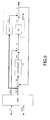
- the entire control system relating to this embodiment is depicted in FIG. 10 .
- the setting values of the injection quantity Q and the engine speed RPM are inputted, and Uref and Xref, which correspond to the setting values of the injection quantity Q and engine speed RPM, are read out from the same table 11 as a table in FIG. 9 .
- a difference Xerr between Xref and the combination X of the measurement values of MAF and MAP is inputted to the controller 12, and the controller 12 calculates the combination Ufb of the feedback control values of the EGR valve opening degree and the VNT nozzle opening degree.
- a new command value U is calculated by adding Uff, which is a result obtained by operating a newly introduced transfer function F2 to Xref, to the sum of Uref and Ufb.
- the command value U is inputted to the transfer function Gpn of the steady-state characteristic model of the engine body 1.
- the ⁇ X is obtained by operating Gpn to U.
- Xref is inputted to the transfer function Gpq2 of the transient response characteristic model of the engine body 1.
- Xq is obtained by operating Gpq2 to Xref.
- F2 is represented similarly to the first embodiment.
- F ⁇ 2 Gd ⁇ 2 - Gpq ⁇ 2 / Gpn
- the transfer function F2 to be set is identified from the transfer function Gd2 of the desired characteristic, the transfer function Gpq2 of the transient response characteristic of the engine body 1 and the transfer function Gpn of the steady-state characteristic.
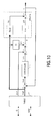
- FIG. 10 is converted to FIG. 11 .
- Uref and Xref which correspond to the setting values of the injection quantity Q and the engine speed RPM, are read out from the same table 11 as a table in FIG. 9 .
- a difference Xerr between the measurement values of the MAF and MAP is inputted to the same controller 12 as a controller in FIG. 9 , and the controller 12 calculates the combination Ufb (also called "feedback amount") of the feedback control values of the EGR valve opening degree and the VNT nozzle opening degree.
- Ufb also called "feedback amount”
- a first intermediate output Xq1 is obtained by operating the newly introduced transfer function Gd2 to Xref.
- a second intermediate output Xq2 is obtained by operating the transfer function Gpq2 corresponding to the transient response characteristic of the engine body 1 to Xref.
- a third intermediate output Xq3 is calculated as a difference between the first intermediate output Xq1 and the second intermediate output Xq2, and a dynamic feedforward amount Uff is calculated by operating inverse conversion 1/Gpn of the transfer function Gpn corresponding to the steady-state characteristic of the engine body 1 to the third intermediate output Xq3.
- a third intermediate output Xq3 is calculated as a difference between the first intermediate output Xq1 and the second intermediate output Xq2, and a dynamic feedforward amount Uff is calculated by operating inverse conversion 1/Gpn of the transfer function Gpn corresponding to the steady-state characteristic of the engine body 1 to the intermediate output Xq3.
- a new command value U is calculated by adding Uref, Ufb and Uff.
- the command value U is inputted to the transfer function Gpn of the steady-state characteristic model of the engine body 1.
- ⁇ X is obtained by operating Gpn to the command value U.
- Gpn is represented by the expression (1), similarly to the first embodiment.
- Gpq2 is represented by a following expression.
- Xq ⁇ 2 t A q * Xq ⁇ 2 ⁇ t - 1 + B q ⁇ 2 * Xref t
- a value, which varies according to Xref[t] is added to a value depending on Xq2[t-1], which is a value before one unit time.
- Aq and Bq2 are matrices to which the transient characteristic of the actual engine body 1 is reflected.
- B q ⁇ 2 B q ⁇ 211 B q ⁇ 212 B q ⁇ 221 B q ⁇ 222
- Gd2 is represented by a following expression.
- Xq ⁇ 1 t A d * Xq ⁇ 1 ⁇ t - 1 + B d ⁇ 2 * Xref t
- Ad and Bd are matrices corresponding to the desired characteristics.
- B d ⁇ 2 B d ⁇ 211 B d ⁇ 212 B d ⁇ 221 B d ⁇ 222
- an engine control apparatus 200 relating to this embodiment has a configuration as depicted in FIG. 12 .
- the same reference numbers are attached to the same elements as the first embodiments.
- the engine body 1 includes the MAP sensor 2 and the MAF sensor 3.
- the setting values of the injection quantity Q and engine speed RPM are values set in response to an instruction from a driver or the like, and provided to the engine control apparatus 200 from the outside.
- an injection quantity measurement unit and engine speed measurement unit may be provided and the setting values may be provided from those units.
- the engine control apparatus 200 includes (a) an injection quantity obtaining unit 101 to obtain the setting value of the injection quantity Q; (b) an engine speed obtaining unit 102 to obatain the setting value of the engine speed RPM; (c) a senor value obtaining unit 103 to obtain a combination X of the measurement values of the MAF and the MAP from the MAP sensor 2 and the MAF sensor 3; (d) a target table 104 in which Uref and Xref are registered in association with the values of the injection quantity and engine speed; (e) a target value generator 105 to accept the setting value of the injection quantity Q outputted from the injection quantity obtaining unit 101 and the setting value of the engine speed RPM outputted from the engine speed obtaining unit 102 and to read out corresponding Uref and Xref from the target value table 104; (f) a dynamic feedforward amount generator 206 to accept the Xref outputted from the target value generator 105 and to calculate the feedforward amount Uff by carrying out calculations described later; (
- the target value generator 105 generates the target values Xref [t] and Uref[t], which correspond to the setting value Q[t] of the injection quantity and the setting value RPM[t] of the engine speed, by reading out them from the target value table 104 (step S25).
- the feedback amount Ufb[t] is a value generated by the same controller 12 as the conventional one, the detailed explanation is omitted.
- the dynamic feedforward amount generator 206 generates the dynamic feedforward amount Uff[t] by using Xref from the target value generator 105 (step S29).
- Uff[t] g2(Xref[t]) is obtained, and g2 (Xref[t]) represents calculations represented by the expressions (4) to (7).
- the command value generator 108 outputs the command value U[t] to the engine body 1 (step S33), and the engine body 1 adjusts the valve opening degree of the EGR valve and the nozzle opening degree of the VNT according to the command value U[t].
- step S35 the processing returns to the step S23 until the operation of the engine body 1 stops.
- FIG. 14 An example of an effect of the embodiments of this technique will be explained by using FIGs. 14 to 16 .
- the injection quantity Q is changed similarly even in case of using the conventional technique and even in case of using this embodiment.
- the target value of the MAF changes in time base.
- the measurement value of the MAF cannot follow the target value well.
- the embodiment when the embodiment is carried out, the measurement value of the MAF can almost follow the target value.
- FIG. 16 depicts time change of the valve opening degree of the EGR valve, and it can be grasped that the control values are different between the conventional art and the embodiments.
- a large change of the valve opening degree occurs at a time when the target value of the MAF begins to change, and accordingly the followingness to the target value of the MAF is improved and the high-speed response is realized.
- the engine is not limited to the diesel engine, and this technique can be applied to the engine having EGR and VNT.
- the engine control apparatuses as depicted in FIGs. 7 and 12 are computer apparatuses. That is, a Random Access memory (RAM) 2501, a processor 2503, a Read Only Memory (ROM) 2507 and sensors 2515 are connected through a bus 2519 as shown in FIG. 17 .
- a control program for carrying out the processing in the embodiment (and an Operating System (OS) if it exists) is stored in the ROM 2507, and when executed by the processor 2503, they are read out from the ROM 2507 to the RAM 2501.
- the processor 2503 controls the sensors (MAP sensor 2 and MAF sensor 3. According to circumstances, injection quantity measurement unit and engine speed measurement unit), and obtains measurement values.
- intermediate processing data is stored in the RAM 2501.
- the processor 2503 may include the ROM 2507, and may further include the RAM 2501.
- the control program for carrying out the aforementioned processing may be distributed by a computer-readable storage removable disk in which the control program is recorded, and the control program may be written into the ROM 2507 by a ROM writer.
- the hardware such as the processor 2503 and RAM 2501 and the ROM 2507 and the control program (and OS if it exists) systematically cooperate with each other, so that various functions as described above in details are realized.
- the first calculating may include: (b1) calculating first values of the nozzle opening degree of the VNT and the valve opening degree of the EGR based on a first model of the predetermined transient response characteristic, wherein an output of the first model varies according to either of the setting value of the injection quantity and target values of the MAF and the MAP, which correspond to the setting values of the injection quantity and the engine speed; (b2) calculating second values of the nozzle opening degree of the VNT and the valve opening degree of the EGR based on a second model of the transient response characteristic of the engine, wherein an output of the second model varies according to either of the setting value of the injection quantity and target values of the MAF and the MAP, which correspond to the setting values of the injection quantity and the engine speed; and (b3) calculating, the dynamic feedforward amount for the nozzle opening degree of the VNT and the valve opening degree of the EGR, based on a third model for removing influence of a steady-state characteristic of the engine for a difference between the first and second values.
- the predetermined transient characteristic can be realized.
- the aforementioned predetermined transient response characteristic may have a first-order time-lag characteristic having a predetermined time constant. By appropriately setting the time constant, it becomes possible to conduct stable high-speed response.
- this method may further include reading out the target values of the MAP and the MAF, which correspond to the setting values of the injection quantity and the engine speed, from a table in which target values of the MAP and the MAF are registered in association with values of the injection quantity and the engine speed.
- a table may be stored in a memory, and the read target values may be calculated without using the table.
- This method may further include reading out the target values of the valve opening degree of the EGR and the nozzle opening degree of the VNT, which correspond to the setting values of the injection quantity and the engine speed, from a table in which target values of the valve opening degree of the EGR and the nozzle opening degree of the VNT are registered in association with values of the injection quantity and the engine speed.
- a table may be stored in a memory, and the read target values may be calculated without using the table.
- This engine control apparatus as depicted in FIG. 18 includes: (A) a data obtaining unit to obtain a setting value of an injection quantity to an engine having an Exhaust Gas Recirculator (EGR) and a Variable Nozzle Turbo (VNT), a setting value of an engine speed, a measurement value of a Manifold Air Pressure (MAP) of the engine and a measurement value of a Mass Air Flow (MAF) of the engine; (B) a dynamic feedforward amount calculation unit to calculate, for a nozzle opening degree of the VNT and a valve opening degree of the EGR, dynamic feedforward amounts for realizing a predetermined transient response characteristic by compensating a transient response characteristic of the engine, which responds according to either of the setting value of the injection quantity and target values of the MAF and the MAP, which correspond to the setting values of the injection quantity and the engine speed; and (C) a command value calculation unit to calculate command values of the nozzle opening degree of the VNT and the valve opening degree of the EGR from control amounts of the valve opening
Landscapes
- Engineering & Computer Science (AREA)
- Chemical & Material Sciences (AREA)
- Combustion & Propulsion (AREA)
- Mechanical Engineering (AREA)
- General Engineering & Computer Science (AREA)
- Output Control And Ontrol Of Special Type Engine (AREA)
- Combined Controls Of Internal Combustion Engines (AREA)
- Electrical Control Of Air Or Fuel Supplied To Internal-Combustion Engine (AREA)
- Exhaust-Gas Circulating Devices (AREA)
Applications Claiming Priority (1)
| Application Number | Priority Date | Filing Date | Title |
|---|---|---|---|
| JP2009225532A JP5249898B2 (ja) | 2009-09-29 | 2009-09-29 | エンジン制御プログラム、方法及び装置 |
Publications (3)
| Publication Number | Publication Date |
|---|---|
| EP2302186A2 true EP2302186A2 (fr) | 2011-03-30 |
| EP2302186A3 EP2302186A3 (fr) | 2014-08-20 |
| EP2302186B1 EP2302186B1 (fr) | 2016-08-31 |
Family
ID=43414774
Family Applications (1)
| Application Number | Title | Priority Date | Filing Date |
|---|---|---|---|
| EP10174061.1A Active EP2302186B1 (fr) | 2009-09-29 | 2010-08-25 | Appareil et procédé de commande de moteur |
Country Status (3)
| Country | Link |
|---|---|
| US (1) | US8615997B2 (fr) |
| EP (1) | EP2302186B1 (fr) |
| JP (1) | JP5249898B2 (fr) |
Cited By (2)
| Publication number | Priority date | Publication date | Assignee | Title |
|---|---|---|---|---|
| EP2716893A4 (fr) * | 2011-05-26 | 2015-12-09 | Toyota Motor Co Ltd | Appareil de commande pour moteur à combustion interne |
| CN111241649A (zh) * | 2018-11-12 | 2020-06-05 | 宝沃汽车(中国)有限公司 | 发动机瞬态响应能力的分析方法及装置 |
Families Citing this family (10)
| Publication number | Priority date | Publication date | Assignee | Title |
|---|---|---|---|---|
| JP5229402B2 (ja) * | 2009-12-21 | 2013-07-03 | 富士通株式会社 | エンジン制御プログラム、方法及び装置 |
| JP5364610B2 (ja) * | 2010-02-09 | 2013-12-11 | 三菱重工業株式会社 | 内燃機関の排ガス再循環制御装置 |
| JP5829431B2 (ja) * | 2011-05-23 | 2015-12-09 | 富士通株式会社 | 目標値算出方法及び装置 |
| JP5972597B2 (ja) * | 2012-02-21 | 2016-08-17 | 三菱重工業株式会社 | Egr制御装置およびegr制御装置を備えたエンジン |
| JP6307842B2 (ja) * | 2013-11-11 | 2018-04-11 | 富士通株式会社 | エンジン制御装置、方法及びプログラム |
| JP6077483B2 (ja) * | 2014-03-26 | 2017-02-08 | 本田技研工業株式会社 | 制御装置 |
| US10360321B2 (en) * | 2015-03-02 | 2019-07-23 | Fujitsu Limited | Model generation method and information processing apparatus |
| US10161345B2 (en) * | 2016-01-15 | 2018-12-25 | Achates Power, Inc. | Control of airflow in a uniflow-scavenged, two-stroke cycle, opposed-piston engine during transient operation |
| CN112539113B (zh) * | 2020-11-30 | 2023-01-06 | 潍柴动力股份有限公司 | 一种空气系统控制方法及装置 |
| CN116971884A (zh) * | 2023-08-15 | 2023-10-31 | 中国第一汽车股份有限公司 | 一种发动机转速调整方法、装置、设备及存储介质 |
Family Cites Families (14)
| Publication number | Priority date | Publication date | Assignee | Title |
|---|---|---|---|---|
| US5771867A (en) * | 1997-07-03 | 1998-06-30 | Caterpillar Inc. | Control system for exhaust gas recovery system in an internal combustion engine |
| JP3493981B2 (ja) * | 1997-10-24 | 2004-02-03 | 日産自動車株式会社 | Egr制御装置付内燃機関の過給圧制御装置 |
| US6076353A (en) * | 1999-01-26 | 2000-06-20 | Ford Global Technologies, Inc. | Coordinated control method for turbocharged diesel engines having exhaust gas recirculation |
| JP4221865B2 (ja) * | 2000-01-31 | 2009-02-12 | いすゞ自動車株式会社 | Egr装置付き過給式エンジン |
| CN1195154C (zh) * | 2000-10-05 | 2005-03-30 | 日产自动车株式会社 | 增压器的控制 |
| JP3471744B2 (ja) | 2000-11-17 | 2003-12-02 | 日野自動車株式会社 | 排気タービン過給機の制御方法及び装置 |
| AU2002343384A1 (en) * | 2002-09-19 | 2004-04-08 | Detroit Diesel Corporation | Method for controlling an engine with vgt and egr systems |
| JP2005214153A (ja) | 2004-02-02 | 2005-08-11 | Nissan Diesel Motor Co Ltd | 内燃機関の吸入空気量制御装置及び制御方法 |
| US7591135B2 (en) * | 2004-12-29 | 2009-09-22 | Honeywell International Inc. | Method and system for using a measure of fueling rate in the air side control of an engine |
| DE102006022148B4 (de) * | 2006-05-12 | 2019-05-09 | Bayerische Motoren Werke Aktiengesellschaft | Verfahren zur Regelung der einer Brennkraftmaschine zuzuführenden Gesamt-Luftmasse |
| US20080078176A1 (en) * | 2006-10-02 | 2008-04-03 | International Engine Intellectual Property Company | Strategy for control of recirculated exhaust gas to null turbocharger boost error |
| FR2911635B1 (fr) * | 2007-01-24 | 2009-10-23 | Peugeot Citroen Automobiles Sa | Moteur thermique equipe d'un turbocompresseur et de deux circuits de recirculation des gaz d'echappement de type haute pression et basse pression. |
| US8010276B2 (en) * | 2009-08-31 | 2011-08-30 | International Engine Intellectual Property Company, Llc | Intake manifold oxygen control |
| JP5333120B2 (ja) * | 2009-09-25 | 2013-11-06 | 富士通株式会社 | エンジン制御プログラム、方法及び装置 |
-
2009
- 2009-09-29 JP JP2009225532A patent/JP5249898B2/ja not_active Expired - Fee Related
-
2010
- 2010-08-25 EP EP10174061.1A patent/EP2302186B1/fr active Active
- 2010-09-22 US US12/887,927 patent/US8615997B2/en not_active Expired - Fee Related
Non-Patent Citations (1)
| Title |
|---|
| None |
Cited By (3)
| Publication number | Priority date | Publication date | Assignee | Title |
|---|---|---|---|---|
| EP2716893A4 (fr) * | 2011-05-26 | 2015-12-09 | Toyota Motor Co Ltd | Appareil de commande pour moteur à combustion interne |
| CN111241649A (zh) * | 2018-11-12 | 2020-06-05 | 宝沃汽车(中国)有限公司 | 发动机瞬态响应能力的分析方法及装置 |
| CN111241649B (zh) * | 2018-11-12 | 2023-11-07 | 北汽福田汽车股份有限公司 | 发动机瞬态响应能力的分析方法及装置 |
Also Published As
| Publication number | Publication date |
|---|---|
| EP2302186B1 (fr) | 2016-08-31 |
| EP2302186A3 (fr) | 2014-08-20 |
| JP2011074793A (ja) | 2011-04-14 |
| US8615997B2 (en) | 2013-12-31 |
| JP5249898B2 (ja) | 2013-07-31 |
| US20110077837A1 (en) | 2011-03-31 |
Similar Documents
| Publication | Publication Date | Title |
|---|---|---|
| EP2302186B1 (fr) | Appareil et procédé de commande de moteur | |
| US8560206B2 (en) | Engine control apparatus and method | |
| KR101539019B1 (ko) | 터보차지되는 엔진 시스템에서 다중 통로들을 통한 배기가스 재순환 제어 | |
| US8082091B2 (en) | Method for controlling a turbocharger using a physical model of the turbocharger speed | |
| EP1024264B1 (fr) | Méthode de contrôle d'un moteur diesel turbochargé avec recirculation de gaz d'échappement | |
| CN105275637B (zh) | 多变量低压排气再循环控制 | |
| JP6434285B2 (ja) | 過給システムの制御装置 | |
| US11098662B2 (en) | Compressor override control | |
| US8437946B2 (en) | Intake system control device and method | |
| CN103233825B (zh) | 二级可调增压控制系统的控制方法 | |
| JP5347676B2 (ja) | 内燃機関の制御方法及び制御装置 | |
| US8666636B2 (en) | Control apparatus for internal combustion engine with supercharger | |
| US20220186660A1 (en) | Boost pressure control for electrically assisted turbochargers | |
| CN111206995A (zh) | 用于控制增压系统的方法 | |
| US9347401B2 (en) | Lambda feedback control for robust particulate emissions performance | |
| JP5584570B2 (ja) | エンジン制御プログラム及び装置 | |
| JP6141959B2 (ja) | 学習及び線形化を伴う可変容量タービンベーン制御システム | |
| JPS6130136B2 (fr) | ||
| US7412965B1 (en) | Exhaust control system for an internal combustion engine | |
| Koli et al. | Nonlinear model predictive control of dual loop-exhaust gas recirculation in a turbocharged spark ignited engine | |
| JP2017020357A (ja) | 内燃機関の制御装置 | |
| US12523185B2 (en) | Power determination apparatus and power determination method | |
| JP2015010548A (ja) | エンジンの制御装置 | |
| JP5584531B2 (ja) | エンジン制御プログラム及び装置 | |
| CN116517706A (zh) | 一种基于模型的航空发动机燃油控制系统动态抗饱和方法及装置 |
Legal Events
| Date | Code | Title | Description |
|---|---|---|---|
| PUAI | Public reference made under article 153(3) epc to a published international application that has entered the european phase |
Free format text: ORIGINAL CODE: 0009012 |
|
| AK | Designated contracting states |
Kind code of ref document: A2 Designated state(s): AL AT BE BG CH CY CZ DE DK EE ES FI FR GB GR HR HU IE IS IT LI LT LU LV MC MK MT NL NO PL PT RO SE SI SK SM TR |
|
| AX | Request for extension of the european patent |
Extension state: BA ME RS |
|
| PUAL | Search report despatched |
Free format text: ORIGINAL CODE: 0009013 |
|
| AK | Designated contracting states |
Kind code of ref document: A3 Designated state(s): AL AT BE BG CH CY CZ DE DK EE ES FI FR GB GR HR HU IE IS IT LI LT LU LV MC MK MT NL NO PL PT RO SE SI SK SM TR |
|
| AX | Request for extension of the european patent |
Extension state: BA ME RS |
|
| RIC1 | Information provided on ipc code assigned before grant |
Ipc: F02D 41/14 20060101ALI20140711BHEP Ipc: F02D 41/00 20060101AFI20140711BHEP Ipc: F02D 41/10 20060101ALI20140711BHEP Ipc: F02D 41/18 20060101ALI20140711BHEP |
|
| 17P | Request for examination filed |
Effective date: 20150114 |
|
| RBV | Designated contracting states (corrected) |
Designated state(s): AL AT BE BG CH CY CZ DE DK EE ES FI FR GB GR HR HU IE IS IT LI LT LU LV MC MK MT NL NO PL PT RO SE SI SK SM TR |
|
| 17Q | First examination report despatched |
Effective date: 20150720 |
|
| GRAP | Despatch of communication of intention to grant a patent |
Free format text: ORIGINAL CODE: EPIDOSNIGR1 |
|
| INTG | Intention to grant announced |
Effective date: 20160330 |
|
| GRAS | Grant fee paid |
Free format text: ORIGINAL CODE: EPIDOSNIGR3 |
|
| GRAA | (expected) grant |
Free format text: ORIGINAL CODE: 0009210 |
|
| AK | Designated contracting states |
Kind code of ref document: B1 Designated state(s): AL AT BE BG CH CY CZ DE DK EE ES FI FR GB GR HR HU IE IS IT LI LT LU LV MC MK MT NL NO PL PT RO SE SI SK SM TR |
|
| REG | Reference to a national code |
Ref country code: CH Ref legal event code: EP Ref country code: GB Ref legal event code: FG4D |
|
| REG | Reference to a national code |
Ref country code: IE Ref legal event code: FG4D |
|
| REG | Reference to a national code |
Ref country code: DE Ref legal event code: R096 Ref document number: 602010035943 Country of ref document: DE |
|
| REG | Reference to a national code |
Ref country code: AT Ref legal event code: REF Ref document number: 825189 Country of ref document: AT Kind code of ref document: T Effective date: 20161015 |
|
| REG | Reference to a national code |
Ref country code: LT Ref legal event code: MG4D |
|
| REG | Reference to a national code |
Ref country code: NL Ref legal event code: MP Effective date: 20160831 |
|
| REG | Reference to a national code |
Ref country code: AT Ref legal event code: MK05 Ref document number: 825189 Country of ref document: AT Kind code of ref document: T Effective date: 20160831 |
|
| PG25 | Lapsed in a contracting state [announced via postgrant information from national office to epo] |
Ref country code: NO Free format text: LAPSE BECAUSE OF FAILURE TO SUBMIT A TRANSLATION OF THE DESCRIPTION OR TO PAY THE FEE WITHIN THE PRESCRIBED TIME-LIMIT Effective date: 20161130 Ref country code: LT Free format text: LAPSE BECAUSE OF FAILURE TO SUBMIT A TRANSLATION OF THE DESCRIPTION OR TO PAY THE FEE WITHIN THE PRESCRIBED TIME-LIMIT Effective date: 20160831 Ref country code: HR Free format text: LAPSE BECAUSE OF FAILURE TO SUBMIT A TRANSLATION OF THE DESCRIPTION OR TO PAY THE FEE WITHIN THE PRESCRIBED TIME-LIMIT Effective date: 20160831 Ref country code: FI Free format text: LAPSE BECAUSE OF FAILURE TO SUBMIT A TRANSLATION OF THE DESCRIPTION OR TO PAY THE FEE WITHIN THE PRESCRIBED TIME-LIMIT Effective date: 20160831 |
|
| PG25 | Lapsed in a contracting state [announced via postgrant information from national office to epo] |
Ref country code: GR Free format text: LAPSE BECAUSE OF FAILURE TO SUBMIT A TRANSLATION OF THE DESCRIPTION OR TO PAY THE FEE WITHIN THE PRESCRIBED TIME-LIMIT Effective date: 20161201 Ref country code: SE Free format text: LAPSE BECAUSE OF FAILURE TO SUBMIT A TRANSLATION OF THE DESCRIPTION OR TO PAY THE FEE WITHIN THE PRESCRIBED TIME-LIMIT Effective date: 20160831 Ref country code: AT Free format text: LAPSE BECAUSE OF FAILURE TO SUBMIT A TRANSLATION OF THE DESCRIPTION OR TO PAY THE FEE WITHIN THE PRESCRIBED TIME-LIMIT Effective date: 20160831 Ref country code: NL Free format text: LAPSE BECAUSE OF FAILURE TO SUBMIT A TRANSLATION OF THE DESCRIPTION OR TO PAY THE FEE WITHIN THE PRESCRIBED TIME-LIMIT Effective date: 20160831 Ref country code: ES Free format text: LAPSE BECAUSE OF FAILURE TO SUBMIT A TRANSLATION OF THE DESCRIPTION OR TO PAY THE FEE WITHIN THE PRESCRIBED TIME-LIMIT Effective date: 20160831 Ref country code: LV Free format text: LAPSE BECAUSE OF FAILURE TO SUBMIT A TRANSLATION OF THE DESCRIPTION OR TO PAY THE FEE WITHIN THE PRESCRIBED TIME-LIMIT Effective date: 20160831 |
|
| PG25 | Lapsed in a contracting state [announced via postgrant information from national office to epo] |
Ref country code: EE Free format text: LAPSE BECAUSE OF FAILURE TO SUBMIT A TRANSLATION OF THE DESCRIPTION OR TO PAY THE FEE WITHIN THE PRESCRIBED TIME-LIMIT Effective date: 20160831 Ref country code: RO Free format text: LAPSE BECAUSE OF FAILURE TO SUBMIT A TRANSLATION OF THE DESCRIPTION OR TO PAY THE FEE WITHIN THE PRESCRIBED TIME-LIMIT Effective date: 20160831 |
|
| PG25 | Lapsed in a contracting state [announced via postgrant information from national office to epo] |
Ref country code: PL Free format text: LAPSE BECAUSE OF FAILURE TO SUBMIT A TRANSLATION OF THE DESCRIPTION OR TO PAY THE FEE WITHIN THE PRESCRIBED TIME-LIMIT Effective date: 20160831 Ref country code: SK Free format text: LAPSE BECAUSE OF FAILURE TO SUBMIT A TRANSLATION OF THE DESCRIPTION OR TO PAY THE FEE WITHIN THE PRESCRIBED TIME-LIMIT Effective date: 20160831 Ref country code: BE Free format text: LAPSE BECAUSE OF FAILURE TO SUBMIT A TRANSLATION OF THE DESCRIPTION OR TO PAY THE FEE WITHIN THE PRESCRIBED TIME-LIMIT Effective date: 20160831 Ref country code: CZ Free format text: LAPSE BECAUSE OF FAILURE TO SUBMIT A TRANSLATION OF THE DESCRIPTION OR TO PAY THE FEE WITHIN THE PRESCRIBED TIME-LIMIT Effective date: 20160831 Ref country code: DK Free format text: LAPSE BECAUSE OF FAILURE TO SUBMIT A TRANSLATION OF THE DESCRIPTION OR TO PAY THE FEE WITHIN THE PRESCRIBED TIME-LIMIT Effective date: 20160831 Ref country code: SM Free format text: LAPSE BECAUSE OF FAILURE TO SUBMIT A TRANSLATION OF THE DESCRIPTION OR TO PAY THE FEE WITHIN THE PRESCRIBED TIME-LIMIT Effective date: 20160831 Ref country code: BG Free format text: LAPSE BECAUSE OF FAILURE TO SUBMIT A TRANSLATION OF THE DESCRIPTION OR TO PAY THE FEE WITHIN THE PRESCRIBED TIME-LIMIT Effective date: 20161130 Ref country code: PT Free format text: LAPSE BECAUSE OF FAILURE TO SUBMIT A TRANSLATION OF THE DESCRIPTION OR TO PAY THE FEE WITHIN THE PRESCRIBED TIME-LIMIT Effective date: 20170102 |
|
| REG | Reference to a national code |
Ref country code: DE Ref legal event code: R097 Ref document number: 602010035943 Country of ref document: DE |
|
| PG25 | Lapsed in a contracting state [announced via postgrant information from national office to epo] |
Ref country code: IT Free format text: LAPSE BECAUSE OF FAILURE TO SUBMIT A TRANSLATION OF THE DESCRIPTION OR TO PAY THE FEE WITHIN THE PRESCRIBED TIME-LIMIT Effective date: 20160831 |
|
| PLBE | No opposition filed within time limit |
Free format text: ORIGINAL CODE: 0009261 |
|
| STAA | Information on the status of an ep patent application or granted ep patent |
Free format text: STATUS: NO OPPOSITION FILED WITHIN TIME LIMIT |
|
| 26N | No opposition filed |
Effective date: 20170601 |
|
| PG25 | Lapsed in a contracting state [announced via postgrant information from national office to epo] |
Ref country code: SI Free format text: LAPSE BECAUSE OF FAILURE TO SUBMIT A TRANSLATION OF THE DESCRIPTION OR TO PAY THE FEE WITHIN THE PRESCRIBED TIME-LIMIT Effective date: 20160831 |
|
| REG | Reference to a national code |
Ref country code: CH Ref legal event code: PL |
|
| PG25 | Lapsed in a contracting state [announced via postgrant information from national office to epo] |
Ref country code: MC Free format text: LAPSE BECAUSE OF FAILURE TO SUBMIT A TRANSLATION OF THE DESCRIPTION OR TO PAY THE FEE WITHIN THE PRESCRIBED TIME-LIMIT Effective date: 20160831 |
|
| PG25 | Lapsed in a contracting state [announced via postgrant information from national office to epo] |
Ref country code: CH Free format text: LAPSE BECAUSE OF NON-PAYMENT OF DUE FEES Effective date: 20170831 Ref country code: LI Free format text: LAPSE BECAUSE OF NON-PAYMENT OF DUE FEES Effective date: 20170831 |
|
| REG | Reference to a national code |
Ref country code: FR Ref legal event code: ST Effective date: 20180430 |
|
| REG | Reference to a national code |
Ref country code: IE Ref legal event code: MM4A |
|
| PG25 | Lapsed in a contracting state [announced via postgrant information from national office to epo] |
Ref country code: LU Free format text: LAPSE BECAUSE OF NON-PAYMENT OF DUE FEES Effective date: 20170825 |
|
| PG25 | Lapsed in a contracting state [announced via postgrant information from national office to epo] |
Ref country code: IE Free format text: LAPSE BECAUSE OF NON-PAYMENT OF DUE FEES Effective date: 20170825 |
|
| PG25 | Lapsed in a contracting state [announced via postgrant information from national office to epo] |
Ref country code: FR Free format text: LAPSE BECAUSE OF NON-PAYMENT OF DUE FEES Effective date: 20170831 |
|
| PG25 | Lapsed in a contracting state [announced via postgrant information from national office to epo] |
Ref country code: MT Free format text: LAPSE BECAUSE OF NON-PAYMENT OF DUE FEES Effective date: 20170825 |
|
| PG25 | Lapsed in a contracting state [announced via postgrant information from national office to epo] |
Ref country code: AL Free format text: LAPSE BECAUSE OF FAILURE TO SUBMIT A TRANSLATION OF THE DESCRIPTION OR TO PAY THE FEE WITHIN THE PRESCRIBED TIME-LIMIT Effective date: 20160831 |
|
| PG25 | Lapsed in a contracting state [announced via postgrant information from national office to epo] |
Ref country code: HU Free format text: LAPSE BECAUSE OF FAILURE TO SUBMIT A TRANSLATION OF THE DESCRIPTION OR TO PAY THE FEE WITHIN THE PRESCRIBED TIME-LIMIT; INVALID AB INITIO Effective date: 20100825 |
|
| PG25 | Lapsed in a contracting state [announced via postgrant information from national office to epo] |
Ref country code: CY Free format text: LAPSE BECAUSE OF NON-PAYMENT OF DUE FEES Effective date: 20160831 |
|
| PG25 | Lapsed in a contracting state [announced via postgrant information from national office to epo] |
Ref country code: MK Free format text: LAPSE BECAUSE OF FAILURE TO SUBMIT A TRANSLATION OF THE DESCRIPTION OR TO PAY THE FEE WITHIN THE PRESCRIBED TIME-LIMIT Effective date: 20160831 |
|
| PG25 | Lapsed in a contracting state [announced via postgrant information from national office to epo] |
Ref country code: TR Free format text: LAPSE BECAUSE OF FAILURE TO SUBMIT A TRANSLATION OF THE DESCRIPTION OR TO PAY THE FEE WITHIN THE PRESCRIBED TIME-LIMIT Effective date: 20160831 |
|
| PG25 | Lapsed in a contracting state [announced via postgrant information from national office to epo] |
Ref country code: IS Free format text: LAPSE BECAUSE OF FAILURE TO SUBMIT A TRANSLATION OF THE DESCRIPTION OR TO PAY THE FEE WITHIN THE PRESCRIBED TIME-LIMIT Effective date: 20161231 |
|
| PGFP | Annual fee paid to national office [announced via postgrant information from national office to epo] |
Ref country code: DE Payment date: 20240702 Year of fee payment: 15 |
|
| PGFP | Annual fee paid to national office [announced via postgrant information from national office to epo] |
Ref country code: GB Payment date: 20240701 Year of fee payment: 15 |
|
| REG | Reference to a national code |
Ref country code: DE Ref legal event code: R119 Ref document number: 602010035943 Country of ref document: DE |