EP2302193B1 - Brennstofferwärmungsvorrichtung - Google Patents
Brennstofferwärmungsvorrichtung Download PDFInfo
- Publication number
- EP2302193B1 EP2302193B1 EP10181306A EP10181306A EP2302193B1 EP 2302193 B1 EP2302193 B1 EP 2302193B1 EP 10181306 A EP10181306 A EP 10181306A EP 10181306 A EP10181306 A EP 10181306A EP 2302193 B1 EP2302193 B1 EP 2302193B1
- Authority
- EP
- European Patent Office
- Prior art keywords
- fuel
- heater
- case
- heating device
- heater housing
- Prior art date
- Legal status (The legal status is an assumption and is not a legal conclusion. Google has not performed a legal analysis and makes no representation as to the accuracy of the status listed.)
- Not-in-force
Links
- 239000000446 fuel Substances 0.000 title claims abstract description 575
- 238000010438 heat treatment Methods 0.000 title claims abstract description 153
- 238000009834 vaporization Methods 0.000 claims abstract description 4
- 230000008016 vaporization Effects 0.000 claims abstract description 4
- 238000002347 injection Methods 0.000 claims description 64
- 239000007924 injection Substances 0.000 claims description 64
- 238000002485 combustion reaction Methods 0.000 claims description 16
- 239000007788 liquid Substances 0.000 abstract description 14
- 239000012808 vapor phase Substances 0.000 abstract description 7
- 238000011144 upstream manufacturing Methods 0.000 description 23
- LFQSCWFLJHTTHZ-UHFFFAOYSA-N Ethanol Chemical compound CCO LFQSCWFLJHTTHZ-UHFFFAOYSA-N 0.000 description 10
- 230000004323 axial length Effects 0.000 description 6
- 230000033001 locomotion Effects 0.000 description 5
- 230000001133 acceleration Effects 0.000 description 3
- 238000005485 electric heating Methods 0.000 description 3
- 239000000203 mixture Substances 0.000 description 3
- 230000000717 retained effect Effects 0.000 description 2
- 230000002123 temporal effect Effects 0.000 description 2
- 230000004913 activation Effects 0.000 description 1
- 230000001154 acute effect Effects 0.000 description 1
- 230000004075 alteration Effects 0.000 description 1
- 239000004020 conductor Substances 0.000 description 1
- 239000000498 cooling water Substances 0.000 description 1
- 238000010586 diagram Methods 0.000 description 1
- 230000002349 favourable effect Effects 0.000 description 1
- 239000007791 liquid phase Substances 0.000 description 1
- 238000012986 modification Methods 0.000 description 1
- 230000004048 modification Effects 0.000 description 1
- 230000002028 premature Effects 0.000 description 1
- 230000002035 prolonged effect Effects 0.000 description 1
- 230000000630 rising effect Effects 0.000 description 1
Images


Classifications
-
- F—MECHANICAL ENGINEERING; LIGHTING; HEATING; WEAPONS; BLASTING
- F02—COMBUSTION ENGINES; HOT-GAS OR COMBUSTION-PRODUCT ENGINE PLANTS
- F02M—SUPPLYING COMBUSTION ENGINES IN GENERAL WITH COMBUSTIBLE MIXTURES OR CONSTITUENTS THEREOF
- F02M53/00—Fuel-injection apparatus characterised by having heating, cooling or thermally-insulating means
- F02M53/02—Fuel-injection apparatus characterised by having heating, cooling or thermally-insulating means with fuel-heating means, e.g. for vaporising
-
- F—MECHANICAL ENGINEERING; LIGHTING; HEATING; WEAPONS; BLASTING
- F02—COMBUSTION ENGINES; HOT-GAS OR COMBUSTION-PRODUCT ENGINE PLANTS
- F02M—SUPPLYING COMBUSTION ENGINES IN GENERAL WITH COMBUSTIBLE MIXTURES OR CONSTITUENTS THEREOF
- F02M31/00—Apparatus for thermally treating combustion-air, fuel, or fuel-air mixture
- F02M31/02—Apparatus for thermally treating combustion-air, fuel, or fuel-air mixture for heating
- F02M31/12—Apparatus for thermally treating combustion-air, fuel, or fuel-air mixture for heating electrically
- F02M31/125—Fuel
-
- F—MECHANICAL ENGINEERING; LIGHTING; HEATING; WEAPONS; BLASTING
- F02—COMBUSTION ENGINES; HOT-GAS OR COMBUSTION-PRODUCT ENGINE PLANTS
- F02M—SUPPLYING COMBUSTION ENGINES IN GENERAL WITH COMBUSTIBLE MIXTURES OR CONSTITUENTS THEREOF
- F02M55/00—Fuel-injection apparatus characterised by their fuel conduits or their venting means; Arrangements of conduits between fuel tank and pump F02M37/00
- F02M55/02—Conduits between injection pumps and injectors, e.g. conduits between pump and common-rail or conduits between common-rail and injectors
- F02M55/025—Common rails
-
- F—MECHANICAL ENGINEERING; LIGHTING; HEATING; WEAPONS; BLASTING
- F02—COMBUSTION ENGINES; HOT-GAS OR COMBUSTION-PRODUCT ENGINE PLANTS
- F02M—SUPPLYING COMBUSTION ENGINES IN GENERAL WITH COMBUSTIBLE MIXTURES OR CONSTITUENTS THEREOF
- F02M63/00—Other fuel-injection apparatus having pertinent characteristics not provided for in groups F02M39/00 - F02M57/00 or F02M67/00; Details, component parts, or accessories of fuel-injection apparatus, not provided for in, or of interest apart from, the apparatus of groups F02M39/00 - F02M61/00 or F02M67/00; Combination of fuel pump with other devices, e.g. lubricating oil pump
- F02M63/02—Fuel-injection apparatus having several injectors fed by a common pumping element, or having several pumping elements feeding a common injector; Fuel-injection apparatus having provisions for cutting-out pumps, pumping elements, or injectors; Fuel-injection apparatus having provisions for variably interconnecting pumping elements and injectors alternatively
- F02M63/0225—Fuel-injection apparatus having a common rail feeding several injectors ; Means for varying pressure in common rails; Pumps feeding common rails
-
- Y—GENERAL TAGGING OF NEW TECHNOLOGICAL DEVELOPMENTS; GENERAL TAGGING OF CROSS-SECTIONAL TECHNOLOGIES SPANNING OVER SEVERAL SECTIONS OF THE IPC; TECHNICAL SUBJECTS COVERED BY FORMER USPC CROSS-REFERENCE ART COLLECTIONS [XRACs] AND DIGESTS
- Y02—TECHNOLOGIES OR APPLICATIONS FOR MITIGATION OR ADAPTATION AGAINST CLIMATE CHANGE
- Y02T—CLIMATE CHANGE MITIGATION TECHNOLOGIES RELATED TO TRANSPORTATION
- Y02T10/00—Road transport of goods or passengers
- Y02T10/10—Internal combustion engine [ICE] based vehicles
- Y02T10/12—Improving ICE efficiencies
Definitions
- the present invention relates to a fuel heating device that is provided upstream of a fuel injection device, such as a fuel injection valve, of an internal combustion engine to heat the fuel before being supplied to the fuel injection device.
- a fuel injection device such as a fuel injection valve
- an electric heating device is provided in a fuel supply pipe that leads to the fuel injection device to allow the heat of the electric heating device to be transferred to the fuel flowing along the surface of the heat emitting portion of the electric heating device, but the heat may not be uniformly transferred to the fuel, and a significant amount of cold fuel may be supplied to the fuel injection device depending on the operating condition of the engine. In such a case, the engine may not start up in an adequately stable manner.
- Japanese patent laid open publication No. 05-26130 discloses a fuel heating device in which a heater having an elongated heat emitting portion is provided in a heating region defined immediately upstream of a fuel injection valve, and the fuel is allowed to flow along the length of the heat emitting portion of the heater before being supplied to the fuel injection valve.
- the heat provided by the heater may cause a part of the fuel to be vaporized, and the heater may be exposed to the vapor phase of the fuel.
- the fuel may not be efficiently heated, and the fuel may fail to be properly pressurized owing to the presence of the fuel vapor.
- the exposure of the heater to the vapor phase may even cause a premature failure of the heating wire in the heater.
- Internal combustion engines in particular for automotive uses, are typically provided with a plurality of cylinders.
- a fuel injection valve is provided for each cylinder, and a fuel delivery pipe having a circular cross section distributes the fuel pressurized by a fuel pump to the different fuel injection valves.
- the fuel injection valves are typically provided along the length of the fuel delivery pipe, and this may cause an unevenness in the amounts of fuel that the different fuel injection valves receive.
- a fuel heating device provided with a plurality of heating units that correspond to different cylinders of a multiple cylinder engine
- fuel is distributed to the different heating units via a horizontally extending fuel distribution pipe or other forms of conduits.
- the fuel distribution pipe is normally filled with liquid fuel, but the activation of the heating units may cause fuel vapor to migrate into the fuel distribution pipe.
- a mixture of liquid fuel and vapor fuel coexist in the fuel distribution pipe where the liquid fuel fills the lower part of the fuel distribution pipe while the fuel vapor occupies a space above the upper surface of the liquid fuel.
- Japanese UM laid open publication No. 01-74361 proposes to form a downwardly projecting bulge in the part of the fuel distribution pipe adjacent to the inlet end of each fuel injection valve so that the liquid fuel may be available for each fuel injection valve even when the upper surface of the liquid fuel tilts with respect to the axial line of the fuel distribution pipe.
- the warm part of the fuel rises upward so that the lower part of each downwardly projecting bulge is normally occupied by the cold part of the fuel. Therefore, the cold fuel, instead of the properly heated fuel, may be preferentially supplied to the fuel injection valve.
- the fuel distribution pipe is tilted from a horizontal orientation, and the warmer fuel is collected in the higher end of the fuel distribution pipe while the colder fuel is collected in the lower end of the fuel distribution pipe.
- the temperature of the fuel supplied to each fuel injection valve may varying from one fuel injection valve to another, and this may cause an unstable operation of the engine.
- WO 2009/009846 discloses a fuel heating device provided between a fuel supply passage communicating with a fuel source and a fuel injection device for injecting fuel into a combustion chamber of an internal combustion engine, comprising a heater housing defining a heating chamber, and including a bottom wall, an inlet opening 2.6 provided in a lower part of the heater housing and an outlet opening 2.2 provided in an upper part of the heater housing diametrically opposite to the inlet opening, and a heater member including a heat emitting portion received in a middle part of the heating chamber.
- the fuel is introduced from the communication orifice 26 provided in a lower part of the heating chamber, and is expelled from the outlet 4a provided in an upper part of the heating chamber. Therefore, again, the fuel flow is generally directed upward.
- a primary object of the present invention is to provide a fuel heating device that can prevent the exposure of the heater to the vapor phase of the fuel.
- a second object of the present invention is to provide a fuel heating device that ensures an efficient heating of the fuel at all times.
- a third object of the present invention is to provide a fuel heating device for a multiple cylinder engine that ensures an even distribution of fuel to the different cylinders.
- a fourth object of the present invention is to provide a fuel heating device for a multiple cylinder engine that can distribute fuel to different cylinders at a uniform temperature.
- the fuel heating device is provided between a fuel supply passage communicating with a fuel source and a fuel injection device for injecting fuel into a combustion chamber of an internal combustion engine, comprising: a heater housing defining a heating chamber therein, and including a bottom wall, an upper inlet opening provided in an upper part of the heater housing and an outlet opening provided in a lower part of the heater housing diametrically opposite to the inlet opening; and a heater member including a heat emitting portion received in a middle part of the heating chamber.
- the inlet opening is provided in an upper part of the fuel housing, bubbles that may be created by the vaporization of the fuel heated by the heater member is allowed to rise upward and then escape out of the inlet opening.
- the bubbles that have returned to the fuel supply passage are cooled by fresh fuel, and condense to liquid state once again. Therefore, the heater housing and fuel supply passage are kept free from the presence of fuel vapor, and the fuel therein can be pressurized by a fuel pump to a proper level at all times. Also, the presence of fuel vapor in the heating chamber is controlled so that the heater member is prevented from being exposed to the vapor phase of the fuel.
- the inlet opening and outlet opening are provided at difference elevations, a circulating flow of fuel is produced in the fuel chamber, and this contributes to the uniform heating of the fuel in the fuel chamber. This can be enhanced even further if the bottom wall is given with a rounded or otherwise smooth surface.
- the heater housing includes an upper side wall slanted with respect to a horizontal plane, and the upper inlet opening is formed in a part of the upper side wall at a higher elevation than a center of the heat emitting portion of the heater member, the bubbles are allowed to travel along the slanted upper side wall so that the movement thereof toward the fuel inlet opening is favorably promoted.
- the heater housing further includes a lower inlet opening provided in a lower part of the upper side wall on a same side of the heater housing as the upper inlet opening.
- the fuel supply passage is partly defined by a fuel case attached to an upper side wall of the heater housing, and having a back wall encompassing both the upper and lower inlet openings, and a pair of outlet ports formed in the back wall so as to align with the upper and lower inlet openings.
- a relatively cold part of the fuel in the fuel supply passage is preferentially admitted into the heating chamber from the lower inlet opening, and this contributes to the uniform heating of the fuel across the fuel supply passage and heating chamber.
- a circulation flow is particularly enhanced if the fuel housing has a cylindrical shape having a central axial line slanted with respect to a vertical plumb line and a hemispherical bottom wall.
- the upper inlet opening has a greater opening area than the lower inlet opening.
- relatively cold fuel is introduced into the heating chamber via the lower inlet opening but also relatively warm fuel is introduce into the heating chamber via the upper inlet opening so that the overall heating efficiency by the heater member can be improved.
- the heat emitting portion of the heater member comprises a rod-shaped portion which extends along the axial line of the heater housing and terminates at a small distance from the bottom wall of the heater housing.
- the heater member heats the fuel in the heating chamber, and creates an upward flow of the fuel. This combined with the creation of bubbles ensures that the bubbles reach the upper inlet opening, and that a circulating convection flow is promoted in the heating chamber.
- the fuel heating device may comprise a plurality of heater housings, a fuel case elongated in an axial direction thereof and provided with a plurality of fuel outlet ports communicating with inlet openings of the corresponding heater housings and at least one fuel inlet port provided at an equal distance from each of the corresponding fuel outlet ports.
- the fuel from the at least one fuel inlet port is distributed evenly to the associated fuel outlet ports in terms of flow rate and pressure.
- the evenly distributed fuel is heated by each heater member evenly for each cylinder.
- a pair of fuel outlet ports are provided in the fuel case for each fuel inlet port. If there are four or more cylinders, there may be two or more inlet ports. In such a case, a tournament flow system may be provided for the fuel supply passage so that an even distribution of fuel from a common source to different cylinders may be ensured.
- the fuel outlet ports of the fuel case may be placed at a higher elevation than the fuel inlet ports thereof.
- the fresh cold fuel admitted from the fuel inlet port pushes the fuel already received in the fuel case and warmed by heat conduction from the heater housing to be pushed upward toward the fuel outlet port so that the warmer part of the fuel is preferentially pushed into each heating chamber. Therefore, the heating efficiency of the heater member can be improved, and the dissipation of heat from the fuel case can be minimized.
- the fuel inlet ports are preferably provided in a lower part of the fuel case so that the fuel flow may occur over the entire height of the fuel case so that very little part of the fuel remains or stagnates in a lower part of the fuel case. This also contributes to the efficient heating of the fuel.
- the fuel case includes a first to fourth outlet ports arranged along the axial line of the fuel case in that order, a first inlet port at a same distance from the first and second outlet ports and a second inlet port at a same distance from the third and fourth outlet ports, an outer section of the fuel case between the first and second outlet ports having a greater cross sectional area than a central section of the fuel case between the second and third outlet ports.
- the fuel case is disposed so as to extend horizontally, and a plurality of upwardly protruding humps each defining a locally enlarged internal volume of the fuel case are provided along the axial line thereof so as to correspond to the different heater housings, each fuel outlet port of the fuel case being provided in an upper part of the corresponding hump. Therefore, the fuel heated by the heat conducted from the heater member rises upward in the fuel case, and is collected in the upper part of each hump where the fuel outlet port is located. Therefore, the warmer fuel is preferentially forwarded to each heating chamber so that the fuel efficiency of the fuel heating device can be improved.
- the warmer fuel is collected in the upper parts of the humps, even when the vehicle is subjected to an acceleration due to cornering or accelerating movements or when the vehicle is tilted due to a slanted road surface, the warmer fuel is retained in the upper parts of the humps, and even those heating chambers communicating with a lower part of the fuel case are allowed to receive a warmer part of the fuel so that the engine can be operated in a stable manner even in a cold condition.
- a distance between central axial lines of the two central humps may be greater than a distance between axial lines of each outer hump and adjacent central hump.
- FIG. 1 a first embodiment of the fuel heating device of the present invention is described in the following.
- the vertical and horizontal directions in Figure 2 substantially coincide with the actual horizontal direction and vertical direction, respectively.
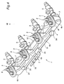
- FIG. 1 illustrates a part of a fuel supply system 1 of an inline, four-cylinder internal combustion engine using ethanol or a mixture containing ethanol for the fuel.
- This fuel supply system 1 includes, for each cylinder, a fuel heating unit 3 for heating the fuel supplied by a common fuel supply pipe 2, and a fuel injection valve 5 provided adjacent to an intake port of the corresponding cylinder for injecting the fuel heated by the fuel heating unit 3 into a corresponding combustion chamber of the engine.
- each fuel injection valve 5 extends at a 45 degree angle with respect to a horizontal plane, but may also extend at any other oblique angles.
- the fuel supply system 1 further comprises a fuel supply pipe 2 which includes an upstream part 2a and a pair of downstream parts 2c branching out from the upstream part 2a via a branching connector 2b.
- the two downstream parts 2c extend in tandem to each other, and in parallel to the cylinder row of the engine.
- the upstream part 2a also extends in parallel with the cylinder row except for the part thereof connected to the branching connector 2b.
- the downstream parts 2c are equal in length so that the upstream part 2a is connected to a middle point of a single linear pipe (downstream parts 2c) via the branching connector 2b in appearance.
- the downstream ends of the downstream parts 2c are connected to a fuel case 4 that extends in parallel with the cylinder row and having a rectangular cross section which is elongated in a direction perpendicular to the axial lines of the fuel injection valves 4 whereas the fuel supply pipe 2 is made of a metallic pipe member having a circular cross section.
- the fuel case 4 extends so as to encompass the four fuel heating units 3, and are provided with four sets of outlet ports that are connected to the different fuel heating units 3 as will be described hereinafter.
- the fuel supply pipe 2 extends generally in parallel with the cylinder row, but the downstream end of the upstream part 2a joins the branching connector extends at a 90 degree angle to the cylinder row.
- the downstream end of each downstream part 2c of the fuel supply pipe 2 is connected to the fuel case 4 via an elbow connector 2d having an inlet port directed in parallel with the cylinder row and an outlet port directed perpendicular to the cylinder row.
- the upstream end of the fuel supply pipe 2 is connected to a fuel pump not shown in the drawings.
- the fuel pump When the ignition switch is turned from the ACC position to the IG position, the fuel pump is activated, and fuel under a prescribed pressure is supplied to the fuel supply pipe 2.
- the fuel fed into the upstream part 2a of the fuel supply pipe 2 is split into two equal parts which are then forwarded to two axially separated parts of the fuel case 4.
- the two equal parts are equal to each other in terms of flow rate, pressure, temperature and velocity components.
- Each fuel heating unit 3 is attached to the lower oblique surface of the fuel case 4 where a corresponding fuel outlet is formed or to the downstream end of the fuel case 4.
- the fuel heating unit 3 includes a resistive heater 8 which is configured to heat the fuel received in the fuel heating unit 3.
- An ECU (electronic control unit) not shown in the drawings controls the supply of electric current from an onboard battery to the heater 8 by a duty ratio control according to the temperature of the cooling water and other data.
- the fuel heating units 3 are activated upon pressing of an engine start button not shown in the drawings, and a preheating of the fuel is performed at the same time.
- the fuel injection valves start injecting fuel into the combustion chambers, and the engine is started. Once the engine is started, the fuel heating units 3 continue the heating of the fuel in a post-start mode until the need for heating the fuel ends.
- Each fuel injection valve 5 is connected to the downstream end of the corresponding fuel heating unit 3.
- the fuel injection valve 5 is incorporated with a solenoid valve which is controlled by an ECU, and is configured to inject a prescribed amount of fuel into the combustion chamber of the engine at a prescribed timing by operating the solenoid valve in a corresponding manner.
- All of the fuel heating units 3 and fuel injection valves 5 are jointly mounted on a common base plate 10 so that the assembling of the fuel heating units 3 and fuel injection valves 5 to the engine may be simplified, and the positional precision of the fuel injection valves 5 with respect to the engine may be ensured.
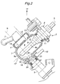
- each fuel heating unit 3 is provided between the fuel case 4 and the corresponding fuel injection valve 5, and comprises a heater housing 7 defining a heating chamber 6 therein.
- the heating chamber 6 receives the working end of the heater 8 therein.
- the heater housings 7 are formed independently from each other and from the fuel case 4. However, if desired, the heater housings 7 may be formed integrally with the fuel case 4 by suitably forming bulges in the fuel case 4.
- Each heater housing 7 is given with a substantially cylindrical shape whose axial line A is tilted with respect to the horizontal direction, for instance by 45 degrees. More specifically, the axial length of the heater housing 7 is substantially greater than the outer diameter thereof.
- the upper axial end of the heater housing 7 is provided with an opening 11 for receiving the heater 8.
- the lower axial end of the heater housing 7 is formed with a hemispherical bottom wall 17.
- the bottom wall 17 may be shaped approximately hemispherical as long as a smooth fuel flow is enabled.
- the heater 8 comprises a rod-shaped heater member 9 in a free end thereof (or the working end thereof) including a heat emitting portion 9h.
- the heater member 9 is inserted into the heating chamber 6 while the base end of the heater 8 closes the opening 11.
- the heater member 9 extends centrally in the heating chamber 6 along the axial line A thereof, and the free end 9a thereof is spaced from the bottom wall 17 of the heater housing 7.
- the heat emitting portion 9h is located in the free end 9a of the heater member 9.
- the heat emitting portion 9h is essentially formed by a resistive wire which generates heat when electric current is conducted through the resistive wire.
- the heat emitting portion 9h may extend from the free end 9a thereof over a large part of the axial length of the heater member, such as 70 to 80% of the axial length thereof. In other words, the heat emitting portion 9a of the heater member 9 is limited to a part of the length thereof received within the heating chamber 6.
- An upper side wall 12 of the heater housing 7 located above the heat emitting portion 9h faces the upper lateral side of the heat emitting portion 9h with a part-cylindrical slanted surface.
- the upper side wall 12 is provided with a pair of circular inlet openings 13 and 14 arranged along an upper ridge line 15 of the upper side wall 12 of the heater housing 7.
- Each point of the ridge line 15 may be defined as a highest point of each circumferential line of the heater housing 7.
- the upper inlet opening 13 is provided in an uppermost part of the upper ridge line 15 with respect to the axial direction of the heater housing 7.
- the lower inlet opening 14 is provided in a lowermost part of the upper ridge line 15 with respect to the axial direction of the heater housing 7.
- the upper inlet opening 13 is located above the heat emitting portion 9h of the heater member 9, and the lower inlet opening 14 is located at a substantially same elevation as a middle part of the heat emitting portion 9h.
- the opening area of the upper opening 13 is greater than that of the lower opening 14.
- a lower side wall 16 of the heater housing 7 located below the heat emitting portion 9h faces the lower lateral side of the heat emitting portion 9h with a part-cylindrical slanted surface.
- the hemispherical bottom wall 17 of the heater housing 7 the free end 9a of the heater member 9 with a concave surface thereof.
- the lower side wall 16 is formed with a circular outlet opening 18 located in a lowermost part of a lower trough bottom 19 of the lower side wall 16 of the heater housing 7.
- Each point of the lower trough bottom 19 may be defined as a lowest point of each circumferential line of the heater housing 7. Therefore, the outlet opening 18 is located lower than a middle point of the heat emitting portion 9h, and diametrically opposite to the inlet openings 13 and 14.
- the base plate 10 is formed with a through hole 20 that aligns with the outlet opening 18 of the heater housing 7.
- the fuel injection valve 5 is mounted on the base plate 10 in such a manner that a fuel inlet hole 21 of the fuel injection valve 5 formed in an axial end thereof aligns with the through hole 20, and the axial line B of the fuel injection valve 5 extends perpendicularly to the axial line A of the heater housing 7.
- the axial line B of the fuel injection valve 5 is at a 45 degree angle with respect to the horizontal plane, and passes through the center of the heater housing 7.
- the axial line B of the fuel injection valve 5 aligns with the lower inlet opening 14 and outlet opening 18, and is offset from the upper inlet opening 13 along the central axial line A of the heater housing 7. Also, the axial lines of the fuel injection valve 5, upper inlet opening 13, lower inlet opening 14 and outlet opening 18 for each cylinder are all located on a common plane.
- the fuel case 4 is provided with four humps 4a in an upper part thereof so as to correspond to the different cylinders and hence to the different fuel heating units 3.
- the humps 4a are defined by the obliquely upwardly protruding upper wall of the fuel case 4, and provide locally enlarged internal volumes.
- the fuel case 4 is thus provided with two inlet ports and four sets of outlet ports.
- Each set of outlet ports include a pair of outlet ports aligning with the upper inlet opening 13 and lower inlet opening 14 of the corresponding heater housing 7.
- the fuel supply pipe 2 and fuel case 4 jointly form a tournament flow system that evenly distributes the fuel fed from the upstream part 2a of the fuel supply 2 to the four sets of fuel outlet ports of the fuel case 4 for the four different cylinders by splitting the flow at the branch connector 2b and elbow connectors 2d.
- each fuel inlet port of the fuel case 4 is located at an equal distance from the two adjacent sets fuel outlet ports so that the fuel flow from the upstream part 2a of the fuel supply 2 is split evenly between the two downstream parts 2c, and the fuel flow from each downstream part 2c is split evenly between the two inlet ports of the fuel case 4.
- the cross sectional area of the outer section 4b of the fuel case 4 between one of the outer humps 4a and adjacent central hump 4a is equal to that between the other outer hump 4a and adjacent central hump 4a, and the cross sectional area of the outer section 4b of the fuel case 4 between each outer hump 4a and adjacent central hump 4a is greater than that of the central section 4c between the two central humps 4a.
- the fuel supply system 1 is disposed such that the fuel case 4 extends horizontally during normal use, and the cross sectional area of the central section 4c is smaller than those of the outer sections 4b, the fuel introduced from each inlet port is substantially exclusively and evenly forwarded to the two sets of adjacent outlet ports.
- the central section 4c is longer than that of the outer sections 4b, and this also contributes to directing the fuel introduced from each inlet port substantially exclusively to the two adjacent sets of outlet ports.
- the fuel case 4 has a continuous interior which is common to all of the fuel heating units 3, and has a corresponding large volume. This also contributes to the even distribution of the fuel to the four fuel heating units 3 by avoiding temporal depletion of fuel for the fuel injection valves 5.
- the mode of operation of the fuel heating unit 3 of the illustrated embodiment is described in the following with reference to Figures 3a and 3b .
- the ignition switch Prior to the heating of the fuel, the ignition switch is changed from the ACC position to the IG position, and the fuel of a prescribed pressure is supplied to the heating chamber 6. At this time, air may be trapped in a part of the fuel heating unit 3, in particular in upper parts of the heating chamber 6 and the fuel case 4 which are higher than the upper inlet opening 13.
- the bubbles that have rises along the ridge line 15 are eventually expelled from the upper inlet opening 13 to the fuel case 4.
- the displaced volume in the heating chamber 6 is made up for by an inflow of fuel from the fuel case 4 via the lower inlet opening 14. This promotes the flow of the warmed fuel from the heating chamber 6 into the fuel case 4 via the upper inlet opening 13, and the flow of the cold fuel from the fuel case 4 into the heating chamber via the lower inlet opening 14 so that the counter clockwise convection flow across the fuel case 4 and heating chamber 6 as shown Figure 3b is promoted.
- the overall temperature of the fuel in the heating chamber 6 is controlled, and the generation of bubbles is avoided.
- the fuel vapor is a poor conductor of heat as compared to the liquid fuel. Also, the temperature of the fuel is kept uniform over the entire heating chamber 6, and this also contributes to the efficient heating of the fuel.
- the bubbles that are forwarded to the fuel case 4 is favorably cooled by the liquid fuel of a relatively low temperature that is stored in the fuel case 4, and are allowed to condense into liquid fuel. Therefore, the amount of fuel vapor that may be present in the fuel case 4 can be minimized, and this allows the fuel to be properly pressurized.
- the counter clockwise convection flow is amplified, and the exchange of fuel between the fuel case 4 and heating chamber 6 is actively performed so that the a uniform temperature distribution across the fuel case 4 and heating chamber 6 can be achieved.
- a gas component that may be present in the heating chamber 6 can be quickly removed to the fuel case 4 so that the presence of gas or bubbles in the heating chamber 6 can be minimized.
- the cold fuel in the fuel case 4 can be readily admitted into the heating chamber 6 so that the fuel in the fuel case 4 and heating chambers 6 is generally warmed, and this contributes to the favorable control of the temperature in the heating chambers 6.
- the fuel in the heater housing 6 is forwarded to each fuel injection valve 5 to be injected into the corresponding combustion chamber, and the fuel corresponding in amount to that injected by the fuel injection valve 5 is supplied from the fuel case 4 to the heating chamber 6.
- the opening area of the upper inlet opening 13 is greater than that of the lower inlet opening 14, the fuel from the fuel case 4 is at least partly admitted into the heating chamber 6 via the upper inlet opening 13. Therefore, the relatively warm fuel located in the upper part of the fuel case 4 is preferentially forwarded to the heating chamber 6, and this contributes to the improvement in the efficiency of heating the fuel.
- the outlet opening 18 of the heater housing 7 is located on the opposite side of the inlet openings 13 and 14 with respect to the heat emitting portion 9h, the fuel that has flowed into the heating chamber 6 via the inlet openings 13 and 14 is heated by the heat emitting portion 9h before leaving the heating chamber 6 from the outlet opening 18 without fail.
- the outlet opening 18 is located lower than the middle point of the heat emitting portion 9h of the heater member 9, the bubbles that may be produced in the heating chamber 6 are prevented from being expelled from the outlet opening 18, and hence from being forwarded to the fuel injection valve 5.
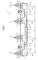
- FIGS. 4 to 6 show a second embodiment of the present invention.
- the parts corresponding to those of the first embodiment are denoted with like numerals without repeating the description of such parts.
- the engine again consists of an inline, four-cylinder internal combustion engine using ethanol or a mixture containing ethanol for the fuel.
- the fuel supply system 1 for this engine comprises, for each cylinder, a fuel injection valve 5 for injecting fuel into the intake port of the corresponding cylinder and a fuel heating unit 3 connected to an upstream end of the fuel injection valve 5.
- the fuel supply system 1 further comprises a fuel supply pipe 2 which includes an upstream part 2a and a pair of downstream parts 2c branching out from the upstream part 2a via a branching connector 2b.
- the two downstream parts 2c extend in tandem to each other, and in parallel to the cylinder row of the engine.
- the upstream part 2a also extends in parallel with the cylinder row except for the part thereof connected to the branching connector 2b.
- the downstream parts 2c are equal in length so that the upstream part 2a is connected to a middle point of a single linear pipe (downstream parts 2c) via the branching connector 2b in appearance.
- the downstream ends of the downstream parts 2c are connected to a fuel case 4 that extends in parallel with the cylinder row and having a vertically elongated rectangular cross section whereas the fuel supply pipe 2 is made of a metallic pipe member having a circular cross section.
- the fuel case 4 extends so as to encompass the four fuel heating units 3, and are provided with outlet ports 4o that are connected to the different fuel heating units 3 as will be described hereinafter.
- the fuel supply pipe 2 extends generally in parallel with the cylinder row, but the downstream end of the upstream part 2a joins the branching connector extends at a 90 degree angle to the cylinder row.
- the downstream end of each downstream part 2c of the fuel supply pipe 2 is connected to the fuel case 4 via an elbow connector 2d having an inlet port directed in parallel with the cylinder row and an outlet port directed perpendicular to the cylinder row.
- the upstream end of the fuel supply pipe 2 is connected to a fuel pump not shown in the drawings.
- the fuel pump When the ignition switch is turned from the ACC position to the IG position, the fuel pump is activated, and fuel under a prescribed pressure is supplied to the fuel supply pipe 2.
- the fuel fed into the upstream part 2a of the fuel supply pipe 2 is split into two equal parts which are then forwarded to two axially separated parts of the fuel case 4.
- the two equal parts are equal to each other in terms of flow rate, pressure, temperature and velocity components.
- the fuel case 4 is provided with a front wall 4f and a back wall 4g which are both planar and in parallel to each other so that a chamber having a vertically elongated rectangular cross section is defined therebetween.
- This chamber is given with a relatively large volume so that the fuel supplied from the fuel supply pipe 2 via two inlet ports 4i thereof is distributed to the heating chambers 6 evenly in terms of flow rate and temperature.
- the fuel case 4 is provided with four humps 4a in an upper wall thereof so as to correspond to the different cylinders and hence to the different fuel heating units 3.
- the humps 4a are defined by the upwardly protruding upper wall of the fuel case 4, and provide locally enlarged internal volumes.
- the axial lines 7X of the four heater housings 7 are arranged at an equal interval and in parallel to each other.
- the central axial lines 4aX of the two central humps 4a are slightly offset from the corresponding heater housing axial lines 7X in an outward direction thereby defining a central section 4c of the fuel case 4 having a relatively long axial length
- the central axial lines 4aX of the two outer humps 4a are slightly offset from the corresponding heater housing axial lines 7X in an inward direction thereby defining a pair of outer sections 4b having a relatively short axial length.
- the distance L1 between the axial lines 4aX of the two central humps 4a is greater than the distance L2 between the axial lines 4aX of each outer hump 4a and adjacent central hump 4a.
- the branch connector 2b is fixedly attached to the front wall 4f at an axially central position of the fuel case 4 or centrally between the two central humps 4a.
- Each elbow connector 2d is fixedly attached to the front wall 4f centrally between the corresponding outer hump 4a and the adjacent central hump 4a. As illustrated in Figure 6 , each elbow connector 2d communicates the downstream part of the fuel supply pipe 2c with the interior of the fuel case 4 via an inlet port 4i formed in the front wall 4f of the fuel case 4.
- the two inlet ports 4i are formed in a lower part of the front wall 4f at a same elevation.
- the fuel supply pipe 2 and fuel case 4 jointly form a tournament flow system that evenly distributes the fuel fed from the upstream part 2a of the fuel supply 2 to the four fuel outlet ports 4o of the fuel case 4 by splitting the flow at the branch connector 2b and elbow connectors 2d.
- each fuel inlet port 4i of the fuel case 4 is located at an equal distance from the two adjacent fuel outlet ports 4o so that the fuel flow from the upstream part 2a of the fuel supply 2 is split evenly between the two downstream parts 2c, and the fuel flow from each downstream part 2c is split evenly between the two inlet ports 4i of the fuel case 4.
- the cross sectional area of the outer section 4b of the fuel case 4 between one of the outer humps 4a and adjacent central hump 4a is equal to that between the other outer hump 4a and adjacent central hump 4a, and the cross sectional area of the outer section 4b of the fuel case 4 between each outer hump 4a and adjacent central hump 4a is greater than that of the central section 4c between the two central humps 4a.
- the fuel supply system 1 is disposed such that the fuel case 4 extends horizontally during normal use, and the cross sectional area of the central section 4c is smaller than those of the outer sections 4b, the fuel introduced from each inlet port 4i is substantially exclusively and evenly forwarded to the two adjacent outlet ports 4o.
- the central section 4c is longer than that of the outer sections 4b, and this also contributes to directing the fuel introduced from each inlet port 4i substantially exclusively to the two adjacent outlet ports 4o.
- the fuel case 4 has a continuous interior which is common to all of the fuel heating units 3, and has a corresponding large volume. This also contributes to the even distribution of the fuel to the four fuel heating units 3 by avoiding temporal depletion of fuel for the fuel injection valves 5.
- the heater housing 7 of each fuel heating unit 3 has a substantially cylindrical shape, and is attached to the back wall 4g of the fuel case 4 so that the cylindrical heater housings 7 oppose the corresponding humps 4a of the fuel case 4.
- Each heater housing 7 has a hemispherical bottom wall, and the axial length of the heater housing 7 is substantially greater than the outer diameter thereof.
- the heater housing 7 internally defines a heating chamber 6, and is provided with a fuel inlet 13 aligning with the outlet port 4o of the fuel case 4 and a fuel outlet 18 for forwarding fuel to the corresponding fuel injection valve 5.
- the upper end of the heater housing 7 is provided with an opening 11 for receiving the heater 8 which is similar to that of the first embodiment.
- Each fuel injection valve 5 is axially elongated, and is provided adjacent to an intake port of the corresponding cylinder of the engine. As shown in Figures 4 and 6 , the heater housing 7 and fuel injection valve 5 are connected to each other via a base plate 10 which commonly supports the heater housings 7 and fuel injection valves 5 so that the assembling of the fuel supply system 1 to the engine is simplified.
- the base plate 10 is formed with through holes 20 that align with the respective fuel outlets 18 of the fuel housing 7.
- Each fuel injection valve 5 is provided with an inlet 21 that communicates with the heating chamber 6 via the fuel outlet 18 of the heater housing 7 and through hole 20 of the base plate 10.
- the fuel injection valve 5 is incorporated with a solenoid valve which is controlled by an ECU, and is configured to inject a prescribed amount of fuel into the combustion chamber of the engine at a prescribed timing by operating the solenoid valve in a corresponding manner.
- the fuel inlet 13 is provided in an upper end of a cylindrical side wall 19 of the heater housing 7 that defines a side of the heating chamber 6, and the fuel outlet 18 is provided in a lower part of the side wall 19.
- Each fuel injection valve 5 is disposed horizontally such that the axial line 5X of the fuel injection valve 5 extends horizontally, or perpendicularly to the axial line 7X of the heater housing 7.
- the fuel inlet 13 and fuel outlet 18 are located on diametrically opposite sides of the side wall 19 of the heater housing 7, and are vertically offset from each other, with the fuel inlet 13 being located higher than the fuel outlet 18.
- the axial lines of the fuel inlet 13, fuel outlet 18 and heater housing 8 are located on a common plane.
- each of the fuel heating units 3 as the heat emitting portion 9h is heated, the fuel surrounding the heat emitting portion 9h is heated, and rises upward in the heating chamber 6.
- the cold fuel introduced from the fuel inlet 13 initially flows horizontally, and then flows downward. As a result, a vertical convection flow is generated in the heating chamber 6.
- bubbles fuel vapor
- the bubbles are then cooled by the cold fuel flowing into the heater chamber 6 from the fuel inlet 13, and return to the liquid phase. Even if the bubbles fail to be liquefied in the heating chamber 6 and pass by the fuel inlet 13, the bubbles reach the upper end of the heater chamber 6.
- the bubbles that have collected in the upper part of the heater member 9 are eventually liquefied by the cold fuel constantly introduced into the heater chamber 6.
- the heat emitting portion 9h is prevented from being exposed to the vapor phase of the fuel. Because the fuel outlet 18 is provided not only diametrically opposite to the fuel inlet 13 but also at a lower elevation than the fuel inlet 13, the bubbles are prevented from being forwarded to the fuel injection valve 5, and this allows the engine to be operated in a stable manner.
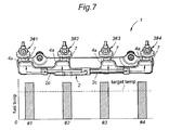
- the fuel in the heater housing 7 is heated by the heater member 9, the heat is also transferred to the interior of the fuel case 4 via heat conduction and via a flow of heated fuel from the heating chamber 6 into the fuel case 4.
- the fuel adjacent to the back wall 4g tends to be warmer than the fuel in other parts of the fuel case 4, and the warmed fuel rises upward. Therefore, the fuel adjacent to the outlet port 4o is particularly warmer than the fuel in other parts of the fuel case 4.
- the inlet port 4i is located lower than the outlet port 4o, the fuel introduced from the downstream part 2c of the fuel supply pipe 2 pushes up the fuel in the fuel case 4, and the warmer fuel is forced toward the outlet port 4o as indicated by arrows in Figure 7 .
- the relatively warm part of the fuel in the fuel case 4 is preferentially expelled from the outlet port 4o and supplied to the fuel injection valve 5 via the heating chamber 6. Therefore, the heat loss from the fuel case 4 is minimized, and the heating efficiency of the heater 8 can be maximized. In other words, the fuel in the fuel housing 7 can be efficiently heated, and the fuel supplied to the fuel injection valves 5 can he heated to a prescribed level under all conditions.
- the inlet ports 4i of the fuel case 4 are provided in a lower part thereof, the fuel in the lower part of the fuel case 4 pushes up the fuel in the remaining part of the fuel case 4, and very little part of the fuel stays in the fuel case 4 for any prolonged period of time.
- the fuel that is introduced into the fuel case 4 from each of the two inlet ports 4i thereof is evenly distributed between the corresponding two heating chambers 6 and hence between the corresponding two fuel injection valves.
- the four fuel injection valves 5 consume a substantially equal amount of fuel. Therefore, as illustrated in Figure 8 , the fuel is heated uniformly by the heater 8 so that the fuel of substantially the same temperature can be supplied to the different fuel injection valves 5, and this ensures a stable operation of the engine.
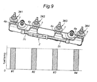
- the fuel supply system 1 is disposed such that the fuel case 4 extends horizontally during normal use, and the fuel case 4 is provided with four upwardly protruding humps 4a so as to correspond to the different fuel heating units 3, even when the fuel case 4 is tilted such that an axial end of the fuel case 4 is raised relative to the other axial end of the fuel case 4 as illustrated in Figure 9 because of a sharp cornering of the vehicle or other causes, the warm fuel is retained in each of the humps 4a, and the supply of warm fuel even to those fuel injection valves 5 brought to lower elevations is not interrupted. Therefore, supply of warm fuel to all of the fuel injection valves 5 is maintained at all times.
- the fuel was split into two parts at the branch connector and elbow connector, respectively, but may also be split into three or more parts.
- the number of inlet ports of the fuel case may not be limited to two but may also be three or other numbers depending on the number of cylinders and other factors.
- the foregoing embodiments were applied to an engine using a fuel containing ethanol, but is equally applicable to other engines using other fuels such as light oil, gasoline or other liquid fuels.
- the engine also may not be limited to a four-cylinder engine, but may also be applied to inline engines having a fewer or larger number of cylinders and V-engines having any number of cylinders.
- the heater housings 7 of the foregoing embodiment were each given with a cylindrical shape having a circular cross section, but may also be given with other shapes such as cubic, prismatic, spherical or the like.
- a fuel heating device comprises a heater housing (7) including a bottom wall (17), an upper inlet opening (13) provided in an upper part of the heater housing and an outlet opening (18) provided in a lower part of the heater housing diametrically opposite to the inlet opening, and a heater member (9) including a heat emitting portion (9h) received in a middle part of a heating chamber (6) defined by the heater housing.
- a heater housing including a bottom wall (17), an upper inlet opening (13) provided in an upper part of the heater housing and an outlet opening (18) provided in a lower part of the heater housing diametrically opposite to the inlet opening, and a heater member (9) including a heat emitting portion (9h) received in a middle part of a heating chamber (6) defined by the heater housing.
- the heater housing and fuel supply passage are kept free from the presence of fuel vapor, and the fuel therein can be pressurized by a fuel pump to a proper level at all times. Also, the presence of fuel vapor in the heating chamber is controlled so that the heater member is prevented from being exposed to the vapor phase of the fuel.
Landscapes
- Engineering & Computer Science (AREA)
- Chemical & Material Sciences (AREA)
- Combustion & Propulsion (AREA)
- Mechanical Engineering (AREA)
- General Engineering & Computer Science (AREA)
- Fuel-Injection Apparatus (AREA)
- Feeding And Controlling Fuel (AREA)
- Wick-Type Burners And Burners With Porous Materials (AREA)
Claims (14)
- Kraftstoffheizvorrichtung, die zwischen einem mit einer Kraftstoffquelle verbundenen Kraftstoffzufuhrkanal (2) und einer Kraftstoffeinspritzvorrichtung (5) zum Einspritzen von Kraftstoff in eine Brennkammer eines Verbrennungsmotors vorgesehen ist, umfassend:ein Heizergehäuse (7), das darin eine Heizkammer (6) definiert; undein Heizelement (9), das einen Wärmeabgabeabschnitt (9h) enthält, der in einem Mittelteil der Heizkammer (6) aufgenommen ist;wobei das Heizergehäuse (7) eine Bodenwand (17) und eine in einem oberen Teil des Heizergehäuses vorgesehene obere Einlassöffnung (13) enthält,dadurch gekennzeichnet, dass es erlaubt, dass Blasen, die durch die Verdampfung des von dem Heizelement (9) erwärmten Kraftstoffs erzeugt werden, aufwärts steigen und dann durch die Einlassöffnung (13) entweichen, sowie eine Auslassöffnung (18) in einem unteren Teil des Heizergehäuses (7) diametral gegenüber der Einlassöffnung (13) vorgesehen ist.
- Die Kraftstoffheizvorrichtung nach Anspruch 1, worin das Heizergehäuse (7) eine obere Seitenwand (12) enthält, die in Bezug auf eine horizontale Ebene geneigt ist, und die obere Einlassöffnung (13) in einem Teil der oberen Seitenwand (12) auf einem höheren Niveau als einer Mitte des Wärmeabgabeabschnitts (9h) des Heizelements (9) ausgebildet ist.
- Die Heizvorrichtung nach Anspruch 2, worin das Heizergehäuse (7) ferner eine untere Einlassöffnung (14) enthält, die in einem unteren Teil der oberen Seitenwand (12) an der gleichen Seite des Heizergehäuses (7) wie die obere Einlassöffnung (13) vorgesehen ist.
- Die Kraftstoffheizvorrichtung nach Anspruch 3, worin die obere Einlassöffnung (13) eine größere Öffnungsfläche als die untere Einlassöffnung (12) hat.
- Die Kraftstoffheizvorrichtung nach Anspruch 3, worin das Kraftstoffgehäuse (7) eine zylindrische Form hat, die eine in Bezug auf eine vertikale Lotlinie schräge Achsmittellinie (A) und eine halbkugelförmige Bodenwand (17) aufweist.
- Die Kraftstoffheizvorrichtung nach Anspruch 5, worin der Wärmeabgabeabschnitt (9h) des Heizelements (9) einen stangenförmigen Abschnitt aufweist, der sich entlang der Achslinie (A) des Heizergehäuses (7) erstreckt und mit geringem Abstand von der Bodenwand (17) des Heizergehäuses (7) endet.
- Die Kraftstoffheizvorrichtung nach Anspruch 5, die ferner ein Kraftstoffgehäuse (4) aufweist, das an einer oberen Seitenwand (12) des Heizergehäuses (7) angebracht ist und eine Rückwand (4g) aufweist, die sowohl die oberen als auch unteren Einlassöffnungen (12, 13) umgibt, sowie ein Paar von Auslassöffnungen, die in der Rückwand (4g) so ausgebildet sind, so dass sie mit den oberen und unteren Einlassöffnungen (13, 14) fluchten.
- Die Kraftstoffheizvorrichtung nach Anspruch 1, worin die Kraftstoffheizvorrichtung umfasst: eine Mehrzahl von Heizergehäusen (7), ein Kraftstoffgehäuse (4), das in seiner Achsrichtung länglich ist und mit einer Mehrzahl von Kraftstoffauslassöffnungen (4o), die mit Einlassöffnungen der entsprechenden Heizergehäuse (7) in Verbindung stehen, und zumindest einer Kraftstoffeinlassöffnung (4i), die mit gleichem Abstand von jeder der entsprechenden Kraftstoffauslassöffnungen vorgesehen ist, versehen ist.
- Die Kraftstoffheizvorrichtung nach Anspruch 8, worin ein Paar von Kraftstoffauslassöffnungen (4o) in dem Kraftstoffgehäuse (4) für jede Kraftstoffeinlassöffnung (4i) vorgesehen ist.
- Die Kraftstoffheizvorrichtung nach Anspruch 9, worin ein Kraftstoffgehäuse (4) so angeordnet ist, dass es sich horizontal erstreckt, und eine Mehrzahl von nach oben vorstehenden Höckern (4a), die jeweils ein örtlich erweitertes Innenvolumen des Kraftstoffgehäuses (4) definieren, entlang deren Achslinie vorgesehen sind, so dass sie den verschiedenen Heizergehäusen (7) entsprechen, wobei jede Kraftstoffauslassöffnung (4o) des Kraftstoffgehäuses (4) in einem oberen Teil des entsprechenden Höckers (4a) vorgesehen ist.
- Die Kraftstoffheizvorrichtung nach Anspruch 10, worin der Motor vier Zylinder in Reihe aufweist und ein Abstand zwischen den Achsmittellinien der zwei mittleren Höcker größer ist als ein Abstand zwischen Achslinien und jedem äußeren Höcker und einem benachbarten mittleren Höcker.
- Die Kraftstoffheizvorrichtung nach Anspruch 8, worin das Kraftstoffgehäuse (4) enthält: erste bis vierte Auslassöffnungen, die entlang der Achslinie des Kraftstoffgehäuses in dieser Reihenfolge angeordnet sind, eine erste Einlassöffnung mit gleichem Abstand von den ersten und zweiten Auslassöffnungen und eine zweite Einlassöffnung mit gleichem Abstand von den dritten und vierten Auslassöffnungen, wobei ein äußerer Abschnitt des Kraftstoffgehäuses zwischen den ersten und zweiten Auslassöffnungen eine größere Querschnittsfläche hat als ein Mittelabschnitt des Kraftstoffgehäuses zwischen den zweiten und dritten Auslassöffnungen.
- Die Kraftstoffheizvorrichtung nach Anspruch 8, worin die Kraftstoffauslassöffnungen auf höherem Niveau als die Kraftstoffeinlassöffnungen angeordnet sind.
- Die Kraftstoffheizvorrichtung nach Anspruch 8, worin die Kraftstoffeinlassöffnungen in einem unteren Teil des Kraftstoffgehäuses vorgesehen sind.
Applications Claiming Priority (3)
| Application Number | Priority Date | Filing Date | Title |
|---|---|---|---|
| JP2009224725A JP5180173B2 (ja) | 2009-09-29 | 2009-09-29 | 燃料加熱装置 |
| JP2009224729A JP5303418B2 (ja) | 2009-09-29 | 2009-09-29 | 燃料供給装置 |
| JP2009224727A JP5303417B2 (ja) | 2009-09-29 | 2009-09-29 | 燃料供給装置 |
Publications (2)
| Publication Number | Publication Date |
|---|---|
| EP2302193A1 EP2302193A1 (de) | 2011-03-30 |
| EP2302193B1 true EP2302193B1 (de) | 2012-02-15 |
Family
ID=43502039
Family Applications (1)
| Application Number | Title | Priority Date | Filing Date |
|---|---|---|---|
| EP10181306A Not-in-force EP2302193B1 (de) | 2009-09-29 | 2010-09-28 | Brennstofferwärmungsvorrichtung |
Country Status (4)
| Country | Link |
|---|---|
| US (1) | US8584655B2 (de) |
| EP (1) | EP2302193B1 (de) |
| AT (1) | ATE545779T1 (de) |
| BR (1) | BRPI1010395A2 (de) |
Families Citing this family (3)
| Publication number | Priority date | Publication date | Assignee | Title |
|---|---|---|---|---|
| DE102014215434A1 (de) * | 2014-08-05 | 2016-02-11 | Mahle International Gmbh | Kraftstoffheizeinrichtung |
| BR102019027845A2 (pt) | 2019-12-26 | 2021-07-06 | Robert Bosch Limitada | sistema e método de gerenciamento de temperatura de combustível injetado em motores de combustão interna |
| BR102019027843A2 (pt) * | 2019-12-26 | 2021-07-06 | Robert Bosch Limitada | sistema e método de gerenciamento de temperatura de combustível injetado em motores de combustão interna |
Family Cites Families (8)
| Publication number | Priority date | Publication date | Assignee | Title |
|---|---|---|---|---|
| US4342303A (en) * | 1980-09-15 | 1982-08-03 | Mccord Robert L | Fuel vaporizer and carburetor preheater system |
| DE3767260D1 (de) | 1986-09-25 | 1991-02-14 | Ganser Hydromag | Kraftstoffeinspritzventil. |
| JPS6474361A (en) | 1987-09-16 | 1989-03-20 | Nippon Pillar Packing | Structure of gland packing box |
| JPH0526130A (ja) | 1991-07-19 | 1993-02-02 | Ngk Spark Plug Co Ltd | ヒータ付燃料供給装置 |
| JPWO2003008796A1 (ja) | 2001-07-16 | 2004-11-11 | 臼井国際産業株式会社 | 燃料圧力脈動抑制システム |
| WO2006130938A1 (en) | 2005-06-06 | 2006-12-14 | Robert Bosch Limitada | A fuel-heating assembly and method for the pre-heating of fuel of an internal combustion engine |
| BRPI0703129B1 (pt) | 2007-07-19 | 2016-12-20 | Bosch Do Brasil | galeria de combustível |
| US8047182B2 (en) * | 2008-02-13 | 2011-11-01 | Millenium Industries | Fuel delivery system for heating fuel therein |
-
2010
- 2010-09-28 AT AT10181306T patent/ATE545779T1/de active
- 2010-09-28 EP EP10181306A patent/EP2302193B1/de not_active Not-in-force
- 2010-09-28 US US12/892,346 patent/US8584655B2/en not_active Expired - Fee Related
- 2010-09-29 BR BRPI1010395-3A patent/BRPI1010395A2/pt not_active Application Discontinuation
Also Published As
| Publication number | Publication date |
|---|---|
| US20110073080A1 (en) | 2011-03-31 |
| ATE545779T1 (de) | 2012-03-15 |
| US8584655B2 (en) | 2013-11-19 |
| EP2302193A1 (de) | 2011-03-30 |
| BRPI1010395A2 (pt) | 2013-05-14 |
Similar Documents
| Publication | Publication Date | Title |
|---|---|---|
| US4601275A (en) | Fuel rail | |
| JP3743281B2 (ja) | 内燃機関の燃料供給装置 | |
| ES2257535T3 (es) | Sistema de alimentacion de combustible. | |
| EP2302193B1 (de) | Brennstofferwärmungsvorrichtung | |
| US8100114B2 (en) | Fuel vaporizer for fuel injected engines | |
| KR20040023801A (ko) | 연료 공급 시스템 | |
| EP2194261B1 (de) | Mit axialem Erhitzervorrichtungslayout ausgestatteter Kraftstoffverteiler zur Motor-Kaltstartoperation mit Ethanol | |
| US8534260B2 (en) | Fuel supply system | |
| JP5303418B2 (ja) | 燃料供給装置 | |
| JP6107521B2 (ja) | 燃料レール | |
| WO2017156541A1 (en) | Fuel vaporizer system with fuel injection | |
| US6843238B2 (en) | Cold start fuel control system | |
| KR200178341Y1 (ko) | 연료 미세분사장치 | |
| CA2768974A1 (en) | Fuel economizer fuel vapor system for internal combustion engine | |
| JP5180173B2 (ja) | 燃料加熱装置 | |
| US9273645B2 (en) | Fluid heating device and vehicle fuel system using the same | |
| US8020537B2 (en) | Fuel economizer fuel vapor system for internal combustion engine | |
| JP5303417B2 (ja) | 燃料供給装置 | |
| JP2012082775A (ja) | 内燃機関の燃料供給装置 | |
| BR102013030510B1 (pt) | Aparelho de aquecimento de fluido | |
| US11378001B2 (en) | Electronic fuel injection type diesel engine | |
| US4201168A (en) | Intake manifold for engine | |
| JP2005325690A (ja) | Lpg用レギュレータ | |
| JP4099770B2 (ja) | 燃料噴射式内燃機関の燃料加熱装置 | |
| JP2022186094A (ja) | エンジンシステム |
Legal Events
| Date | Code | Title | Description |
|---|---|---|---|
| PUAI | Public reference made under article 153(3) epc to a published international application that has entered the european phase |
Free format text: ORIGINAL CODE: 0009012 |
|
| 17P | Request for examination filed |
Effective date: 20100928 |
|
| AK | Designated contracting states |
Kind code of ref document: A1 Designated state(s): AL AT BE BG CH CY CZ DE DK EE ES FI FR GB GR HR HU IE IS IT LI LT LU LV MC MK MT NL NO PL PT RO SE SI SK SM TR |
|
| AX | Request for extension of the european patent |
Extension state: BA ME RS |
|
| 17Q | First examination report despatched |
Effective date: 20110328 |
|
| GRAP | Despatch of communication of intention to grant a patent |
Free format text: ORIGINAL CODE: EPIDOSNIGR1 |
|
| GRAS | Grant fee paid |
Free format text: ORIGINAL CODE: EPIDOSNIGR3 |
|
| GRAA | (expected) grant |
Free format text: ORIGINAL CODE: 0009210 |
|
| AK | Designated contracting states |
Kind code of ref document: B1 Designated state(s): AL AT BE BG CH CY CZ DE DK EE ES FI FR GB GR HR HU IE IS IT LI LT LU LV MC MK MT NL NO PL PT RO SE SI SK SM TR |
|
| REG | Reference to a national code |
Ref country code: CH Ref legal event code: EP Ref country code: GB Ref legal event code: FG4D |
|
| REG | Reference to a national code |
Ref country code: IE Ref legal event code: FG4D |
|
| REG | Reference to a national code |
Ref country code: AT Ref legal event code: REF Ref document number: 545779 Country of ref document: AT Kind code of ref document: T Effective date: 20120315 |
|
| REG | Reference to a national code |
Ref country code: DE Ref legal event code: R096 Ref document number: 602010000859 Country of ref document: DE Effective date: 20120405 |
|
| REG | Reference to a national code |
Ref country code: NL Ref legal event code: VDEP Effective date: 20120215 |
|
| LTIE | Lt: invalidation of european patent or patent extension |
Effective date: 20120215 |
|
| PG25 | Lapsed in a contracting state [announced via postgrant information from national office to epo] |
Ref country code: HR Free format text: LAPSE BECAUSE OF FAILURE TO SUBMIT A TRANSLATION OF THE DESCRIPTION OR TO PAY THE FEE WITHIN THE PRESCRIBED TIME-LIMIT Effective date: 20120215 Ref country code: IS Free format text: LAPSE BECAUSE OF FAILURE TO SUBMIT A TRANSLATION OF THE DESCRIPTION OR TO PAY THE FEE WITHIN THE PRESCRIBED TIME-LIMIT Effective date: 20120615 Ref country code: LT Free format text: LAPSE BECAUSE OF FAILURE TO SUBMIT A TRANSLATION OF THE DESCRIPTION OR TO PAY THE FEE WITHIN THE PRESCRIBED TIME-LIMIT Effective date: 20120215 Ref country code: NL Free format text: LAPSE BECAUSE OF FAILURE TO SUBMIT A TRANSLATION OF THE DESCRIPTION OR TO PAY THE FEE WITHIN THE PRESCRIBED TIME-LIMIT Effective date: 20120215 Ref country code: NO Free format text: LAPSE BECAUSE OF FAILURE TO SUBMIT A TRANSLATION OF THE DESCRIPTION OR TO PAY THE FEE WITHIN THE PRESCRIBED TIME-LIMIT Effective date: 20120515 |
|
| PG25 | Lapsed in a contracting state [announced via postgrant information from national office to epo] |
Ref country code: LV Free format text: LAPSE BECAUSE OF FAILURE TO SUBMIT A TRANSLATION OF THE DESCRIPTION OR TO PAY THE FEE WITHIN THE PRESCRIBED TIME-LIMIT Effective date: 20120215 Ref country code: FI Free format text: LAPSE BECAUSE OF FAILURE TO SUBMIT A TRANSLATION OF THE DESCRIPTION OR TO PAY THE FEE WITHIN THE PRESCRIBED TIME-LIMIT Effective date: 20120215 Ref country code: BE Free format text: LAPSE BECAUSE OF FAILURE TO SUBMIT A TRANSLATION OF THE DESCRIPTION OR TO PAY THE FEE WITHIN THE PRESCRIBED TIME-LIMIT Effective date: 20120215 Ref country code: PL Free format text: LAPSE BECAUSE OF FAILURE TO SUBMIT A TRANSLATION OF THE DESCRIPTION OR TO PAY THE FEE WITHIN THE PRESCRIBED TIME-LIMIT Effective date: 20120215 Ref country code: PT Free format text: LAPSE BECAUSE OF FAILURE TO SUBMIT A TRANSLATION OF THE DESCRIPTION OR TO PAY THE FEE WITHIN THE PRESCRIBED TIME-LIMIT Effective date: 20120615 Ref country code: GR Free format text: LAPSE BECAUSE OF FAILURE TO SUBMIT A TRANSLATION OF THE DESCRIPTION OR TO PAY THE FEE WITHIN THE PRESCRIBED TIME-LIMIT Effective date: 20120516 |
|
| REG | Reference to a national code |
Ref country code: AT Ref legal event code: MK05 Ref document number: 545779 Country of ref document: AT Kind code of ref document: T Effective date: 20120215 |
|
| PG25 | Lapsed in a contracting state [announced via postgrant information from national office to epo] |
Ref country code: CY Free format text: LAPSE BECAUSE OF FAILURE TO SUBMIT A TRANSLATION OF THE DESCRIPTION OR TO PAY THE FEE WITHIN THE PRESCRIBED TIME-LIMIT Effective date: 20120215 |
|
| PG25 | Lapsed in a contracting state [announced via postgrant information from national office to epo] |
Ref country code: RO Free format text: LAPSE BECAUSE OF FAILURE TO SUBMIT A TRANSLATION OF THE DESCRIPTION OR TO PAY THE FEE WITHIN THE PRESCRIBED TIME-LIMIT Effective date: 20120215 Ref country code: SE Free format text: LAPSE BECAUSE OF FAILURE TO SUBMIT A TRANSLATION OF THE DESCRIPTION OR TO PAY THE FEE WITHIN THE PRESCRIBED TIME-LIMIT Effective date: 20120215 Ref country code: EE Free format text: LAPSE BECAUSE OF FAILURE TO SUBMIT A TRANSLATION OF THE DESCRIPTION OR TO PAY THE FEE WITHIN THE PRESCRIBED TIME-LIMIT Effective date: 20120215 Ref country code: SI Free format text: LAPSE BECAUSE OF FAILURE TO SUBMIT A TRANSLATION OF THE DESCRIPTION OR TO PAY THE FEE WITHIN THE PRESCRIBED TIME-LIMIT Effective date: 20120215 Ref country code: CZ Free format text: LAPSE BECAUSE OF FAILURE TO SUBMIT A TRANSLATION OF THE DESCRIPTION OR TO PAY THE FEE WITHIN THE PRESCRIBED TIME-LIMIT Effective date: 20120215 Ref country code: DK Free format text: LAPSE BECAUSE OF FAILURE TO SUBMIT A TRANSLATION OF THE DESCRIPTION OR TO PAY THE FEE WITHIN THE PRESCRIBED TIME-LIMIT Effective date: 20120215 |
|
| PG25 | Lapsed in a contracting state [announced via postgrant information from national office to epo] |
Ref country code: SK Free format text: LAPSE BECAUSE OF FAILURE TO SUBMIT A TRANSLATION OF THE DESCRIPTION OR TO PAY THE FEE WITHIN THE PRESCRIBED TIME-LIMIT Effective date: 20120215 Ref country code: IT Free format text: LAPSE BECAUSE OF FAILURE TO SUBMIT A TRANSLATION OF THE DESCRIPTION OR TO PAY THE FEE WITHIN THE PRESCRIBED TIME-LIMIT Effective date: 20120215 |
|
| PLBE | No opposition filed within time limit |
Free format text: ORIGINAL CODE: 0009261 |
|
| STAA | Information on the status of an ep patent application or granted ep patent |
Free format text: STATUS: NO OPPOSITION FILED WITHIN TIME LIMIT |
|
| 26N | No opposition filed |
Effective date: 20121116 |
|
| PG25 | Lapsed in a contracting state [announced via postgrant information from national office to epo] |
Ref country code: AT Free format text: LAPSE BECAUSE OF FAILURE TO SUBMIT A TRANSLATION OF THE DESCRIPTION OR TO PAY THE FEE WITHIN THE PRESCRIBED TIME-LIMIT Effective date: 20120215 |
|
| REG | Reference to a national code |
Ref country code: DE Ref legal event code: R097 Ref document number: 602010000859 Country of ref document: DE Effective date: 20121116 |
|
| PG25 | Lapsed in a contracting state [announced via postgrant information from national office to epo] |
Ref country code: ES Free format text: LAPSE BECAUSE OF FAILURE TO SUBMIT A TRANSLATION OF THE DESCRIPTION OR TO PAY THE FEE WITHIN THE PRESCRIBED TIME-LIMIT Effective date: 20120526 Ref country code: MC Free format text: LAPSE BECAUSE OF NON-PAYMENT OF DUE FEES Effective date: 20120930 |
|
| REG | Reference to a national code |
Ref country code: IE Ref legal event code: MM4A |
|
| REG | Reference to a national code |
Ref country code: FR Ref legal event code: ST Effective date: 20130531 |
|
| PG25 | Lapsed in a contracting state [announced via postgrant information from national office to epo] |
Ref country code: BG Free format text: LAPSE BECAUSE OF FAILURE TO SUBMIT A TRANSLATION OF THE DESCRIPTION OR TO PAY THE FEE WITHIN THE PRESCRIBED TIME-LIMIT Effective date: 20120515 Ref country code: IE Free format text: LAPSE BECAUSE OF NON-PAYMENT OF DUE FEES Effective date: 20120928 |
|
| PG25 | Lapsed in a contracting state [announced via postgrant information from national office to epo] |
Ref country code: FR Free format text: LAPSE BECAUSE OF NON-PAYMENT OF DUE FEES Effective date: 20121001 |
|
| PG25 | Lapsed in a contracting state [announced via postgrant information from national office to epo] |
Ref country code: AL Free format text: LAPSE BECAUSE OF FAILURE TO SUBMIT A TRANSLATION OF THE DESCRIPTION OR TO PAY THE FEE WITHIN THE PRESCRIBED TIME-LIMIT Effective date: 20120215 Ref country code: MT Free format text: LAPSE BECAUSE OF FAILURE TO SUBMIT A TRANSLATION OF THE DESCRIPTION OR TO PAY THE FEE WITHIN THE PRESCRIBED TIME-LIMIT Effective date: 20120215 |
|
| PG25 | Lapsed in a contracting state [announced via postgrant information from national office to epo] |
Ref country code: TR Free format text: LAPSE BECAUSE OF FAILURE TO SUBMIT A TRANSLATION OF THE DESCRIPTION OR TO PAY THE FEE WITHIN THE PRESCRIBED TIME-LIMIT Effective date: 20120215 |
|
| PG25 | Lapsed in a contracting state [announced via postgrant information from national office to epo] |
Ref country code: LU Free format text: LAPSE BECAUSE OF NON-PAYMENT OF DUE FEES Effective date: 20120928 Ref country code: SM Free format text: LAPSE BECAUSE OF FAILURE TO SUBMIT A TRANSLATION OF THE DESCRIPTION OR TO PAY THE FEE WITHIN THE PRESCRIBED TIME-LIMIT Effective date: 20120215 |
|
| REG | Reference to a national code |
Ref country code: DE Ref legal event code: R084 Ref document number: 602010000859 Country of ref document: DE Effective date: 20140430 |
|
| PG25 | Lapsed in a contracting state [announced via postgrant information from national office to epo] |
Ref country code: HU Free format text: LAPSE BECAUSE OF FAILURE TO SUBMIT A TRANSLATION OF THE DESCRIPTION OR TO PAY THE FEE WITHIN THE PRESCRIBED TIME-LIMIT Effective date: 20100928 |
|
| REG | Reference to a national code |
Ref country code: CH Ref legal event code: PL |
|
| GBPC | Gb: european patent ceased through non-payment of renewal fee |
Effective date: 20140928 |
|
| PG25 | Lapsed in a contracting state [announced via postgrant information from national office to epo] |
Ref country code: LI Free format text: LAPSE BECAUSE OF NON-PAYMENT OF DUE FEES Effective date: 20140930 Ref country code: CH Free format text: LAPSE BECAUSE OF NON-PAYMENT OF DUE FEES Effective date: 20140930 Ref country code: GB Free format text: LAPSE BECAUSE OF NON-PAYMENT OF DUE FEES Effective date: 20140928 Ref country code: MK Free format text: LAPSE BECAUSE OF FAILURE TO SUBMIT A TRANSLATION OF THE DESCRIPTION OR TO PAY THE FEE WITHIN THE PRESCRIBED TIME-LIMIT Effective date: 20120215 |
|
| PGFP | Annual fee paid to national office [announced via postgrant information from national office to epo] |
Ref country code: DE Payment date: 20150922 Year of fee payment: 6 |
|
| REG | Reference to a national code |
Ref country code: DE Ref legal event code: R119 Ref document number: 602010000859 Country of ref document: DE |
|
| PG25 | Lapsed in a contracting state [announced via postgrant information from national office to epo] |
Ref country code: DE Free format text: LAPSE BECAUSE OF NON-PAYMENT OF DUE FEES Effective date: 20170401 |