EP2302201B1 - Pumpe-System mit Rückgewinnung von Energie - Google Patents
Pumpe-System mit Rückgewinnung von Energie Download PDFInfo
- Publication number
- EP2302201B1 EP2302201B1 EP10181357.4A EP10181357A EP2302201B1 EP 2302201 B1 EP2302201 B1 EP 2302201B1 EP 10181357 A EP10181357 A EP 10181357A EP 2302201 B1 EP2302201 B1 EP 2302201B1
- Authority
- EP
- European Patent Office
- Prior art keywords
- pump
- turbine
- impellers
- pressurization
- axial thrust
- Prior art date
- Legal status (The legal status is an assumption and is not a legal conclusion. Google has not performed a legal analysis and makes no representation as to the accuracy of the status listed.)
- Not-in-force
Links
- 238000011084 recovery Methods 0.000 title description 26
- XLYOFNOQVPJJNP-UHFFFAOYSA-N water Substances O XLYOFNOQVPJJNP-UHFFFAOYSA-N 0.000 claims description 46
- ZZUFCTLCJUWOSV-UHFFFAOYSA-N furosemide Chemical compound C1=C(Cl)C(S(=O)(=O)N)=CC(C(O)=O)=C1NCC1=CC=CO1 ZZUFCTLCJUWOSV-UHFFFAOYSA-N 0.000 claims description 37
- 239000012528 membrane Substances 0.000 claims description 21
- 238000001223 reverse osmosis Methods 0.000 claims description 21
- 239000002351 wastewater Substances 0.000 claims description 4
- 238000010612 desalination reaction Methods 0.000 description 12
- 239000013535 sea water Substances 0.000 description 9
- 230000009467 reduction Effects 0.000 description 7
- 239000012535 impurity Substances 0.000 description 5
- 239000004696 Poly ether ether ketone Substances 0.000 description 4
- 230000008859 change Effects 0.000 description 4
- 238000004891 communication Methods 0.000 description 4
- 238000005461 lubrication Methods 0.000 description 4
- 238000012423 maintenance Methods 0.000 description 4
- 239000000463 material Substances 0.000 description 4
- 238000000034 method Methods 0.000 description 4
- 230000002093 peripheral effect Effects 0.000 description 4
- 229920002530 polyetherether ketone Polymers 0.000 description 4
- 230000008569 process Effects 0.000 description 4
- 150000003839 salts Chemical class 0.000 description 4
- 238000013461 design Methods 0.000 description 3
- 239000012530 fluid Substances 0.000 description 3
- 230000007246 mechanism Effects 0.000 description 3
- 239000012466 permeate Substances 0.000 description 3
- 230000008901 benefit Effects 0.000 description 2
- 238000005516 engineering process Methods 0.000 description 2
- 230000002349 favourable effect Effects 0.000 description 2
- 230000035515 penetration Effects 0.000 description 2
- 230000001105 regulatory effect Effects 0.000 description 2
- 239000011347 resin Substances 0.000 description 2
- 229920005989 resin Polymers 0.000 description 2
- 238000007789 sealing Methods 0.000 description 2
- 230000003068 static effect Effects 0.000 description 2
- 230000001133 acceleration Effects 0.000 description 1
- 230000008878 coupling Effects 0.000 description 1
- 238000010168 coupling process Methods 0.000 description 1
- 238000005859 coupling reaction Methods 0.000 description 1
- 230000001419 dependent effect Effects 0.000 description 1
- 238000007599 discharging Methods 0.000 description 1
- 230000035622 drinking Effects 0.000 description 1
- 210000004907 gland Anatomy 0.000 description 1
- 230000006872 improvement Effects 0.000 description 1
- 238000009434 installation Methods 0.000 description 1
- 239000007788 liquid Substances 0.000 description 1
- 239000000314 lubricant Substances 0.000 description 1
- 230000004044 response Effects 0.000 description 1
- 238000012546 transfer Methods 0.000 description 1
Images
Classifications
-
- F—MECHANICAL ENGINEERING; LIGHTING; HEATING; WEAPONS; BLASTING
- F03—MACHINES OR ENGINES FOR LIQUIDS; WIND, SPRING, OR WEIGHT MOTORS; PRODUCING MECHANICAL POWER OR A REACTIVE PROPULSIVE THRUST, NOT OTHERWISE PROVIDED FOR
- F03B—MACHINES OR ENGINES FOR LIQUIDS
- F03B3/00—Machines or engines of reaction type; Parts or details peculiar thereto
- F03B3/02—Machines or engines of reaction type; Parts or details peculiar thereto with radial flow at high-pressure side and axial flow at low-pressure side of rotors, e.g. Francis turbines
-
- F—MECHANICAL ENGINEERING; LIGHTING; HEATING; WEAPONS; BLASTING
- F04—POSITIVE - DISPLACEMENT MACHINES FOR LIQUIDS; PUMPS FOR LIQUIDS OR ELASTIC FLUIDS
- F04D—NON-POSITIVE-DISPLACEMENT PUMPS
- F04D13/00—Pumping installations or systems
- F04D13/02—Units comprising pumps and their driving means
- F04D13/04—Units comprising pumps and their driving means the pump being fluid driven
-
- F—MECHANICAL ENGINEERING; LIGHTING; HEATING; WEAPONS; BLASTING
- F05—INDEXING SCHEMES RELATING TO ENGINES OR PUMPS IN VARIOUS SUBCLASSES OF CLASSES F01-F04
- F05B—INDEXING SCHEME RELATING TO WIND, SPRING, WEIGHT, INERTIA OR LIKE MOTORS, TO MACHINES OR ENGINES FOR LIQUIDS COVERED BY SUBCLASSES F03B, F03D AND F03G
- F05B2220/00—Application
- F05B2220/60—Application making use of surplus or waste energy
- F05B2220/602—Application making use of surplus or waste energy with energy recovery turbines
-
- F—MECHANICAL ENGINEERING; LIGHTING; HEATING; WEAPONS; BLASTING
- F05—INDEXING SCHEMES RELATING TO ENGINES OR PUMPS IN VARIOUS SUBCLASSES OF CLASSES F01-F04
- F05B—INDEXING SCHEME RELATING TO WIND, SPRING, WEIGHT, INERTIA OR LIKE MOTORS, TO MACHINES OR ENGINES FOR LIQUIDS COVERED BY SUBCLASSES F03B, F03D AND F03G
- F05B2220/00—Application
- F05B2220/62—Application for desalination
-
- Y—GENERAL TAGGING OF NEW TECHNOLOGICAL DEVELOPMENTS; GENERAL TAGGING OF CROSS-SECTIONAL TECHNOLOGIES SPANNING OVER SEVERAL SECTIONS OF THE IPC; TECHNICAL SUBJECTS COVERED BY FORMER USPC CROSS-REFERENCE ART COLLECTIONS [XRACs] AND DIGESTS
- Y02—TECHNOLOGIES OR APPLICATIONS FOR MITIGATION OR ADAPTATION AGAINST CLIMATE CHANGE
- Y02B—CLIMATE CHANGE MITIGATION TECHNOLOGIES RELATED TO BUILDINGS, e.g. HOUSING, HOUSE APPLIANCES OR RELATED END-USER APPLICATIONS
- Y02B10/00—Integration of renewable energy sources in buildings
- Y02B10/50—Hydropower in dwellings
-
- Y—GENERAL TAGGING OF NEW TECHNOLOGICAL DEVELOPMENTS; GENERAL TAGGING OF CROSS-SECTIONAL TECHNOLOGIES SPANNING OVER SEVERAL SECTIONS OF THE IPC; TECHNICAL SUBJECTS COVERED BY FORMER USPC CROSS-REFERENCE ART COLLECTIONS [XRACs] AND DIGESTS
- Y02—TECHNOLOGIES OR APPLICATIONS FOR MITIGATION OR ADAPTATION AGAINST CLIMATE CHANGE
- Y02E—REDUCTION OF GREENHOUSE GAS [GHG] EMISSIONS, RELATED TO ENERGY GENERATION, TRANSMISSION OR DISTRIBUTION
- Y02E10/00—Energy generation through renewable energy sources
- Y02E10/20—Hydro energy
Definitions
- the present invention relates to a pump system having an energy recovery apparatus used in, e.g., a seawater desalination plant to recover power from energy of concentrated water.
- a pump system as described in the preamble portion of patent claim 1 has been known from IT 1272453 B .
- seawater desalination plants The market for seawater desalination plants is expected to expand because of, e.g., a growing worldwide need for water and water shortage due to climate change. Water supplied from seawater desalination plants is important for infrastructure. Therefore, reduction of desalination cost and maintenance of water quality for drinking are desirable. Particularly in the reduction of the desalination cost, higher efficiency is desirable for reduction in plant cost and running cost of a reverse osmosis membrane pressurization pump that consumes about fifty percent of electrical energy supplied to the plant.
- reverse osmosis membrane pressurization pumps have a discharge quantity of 600 to 3, 000 m 3 /h, a net pump head of 550 to 740 m, and a pump shaft power of 1,000 to 6,000 kW.
- the reverse osmosis membrane pressurization pumps use multistage centrifugal diffuser pumps.
- Pelton turbines are used in the energy recovery apparatus using concentrated water. As discussed in JP 6-210140 A , in the usage of energy of concentrated water, an output shaft of the Pelton turbine is coupled to a main shaft of a motor driving a pressurization pump to use rotational energy recovered by the Pelton turbine as part of driving force for the pressurization pump. In such a way, energy saving for the pressurization pump is achieved.
- An amount and pressure of the concentrated water is about 300 to 1,800 m 3 /h
- the head is 500 to 700 m
- its energy is about 500 to 3,600 kW, which is large to reach about 40 to 60 percent of the pressurization pump driving force.
- IT 272452 B discloses a pump system having an energy recover apparatus, the pump system comprising a pressurization pump; and a hydro turbine used for the energy recover apparatus, the energy recover apparatus recovering energy from high-pressure concentrated waste water to use the energy as driving force for the pressurization pump when raw water pressurized by the pressurization pump is filtered by a reverse osmosis membrane, the hydro turbine having multistage turbine impellers coaxial with a rotation shaft of the pressurization pump, the turbine impellers being disposed opposite pump impellers of the pressurization pump.
- the present invention is a pump system having an energy recovery apparatus which recovers energy from high-pressure concentrated waste water through a reverse osmosis membrane to use the energy as driving force for the pressurization pump when raw water pressurized by a pressurization pump is filtered by the reverse osmosis membrane.
- the energy recovery apparatus uses a hydro turbine having multistage turbine impellers coaxial with a rotation shaft of the pressurization pump. The turbine impellers are disposed opposite pump impellers of the pressurization pump.
- the pump system having the energy recovery apparatus includes an axial thrust support device which supports an axial thrust of the turbine impellers and an axial thrust of the pump impellers.
- the pressurization pump and the hydro turbine are disposed to position an inlet side (low pressure side) of the pressurization pump and an outlet side (low pressure side) of the hydro turbine adjacent one another.
- the rotation shaft for the pressurization pump and hydro turbine is supported by a radial submerged bearing.
- the axial thrust support device is an axial thrust balancing device using a balancing disc.
- an end of the rotation shaft for the pressurization pump and hydro turbine has a non-seal structure using an end cover.
- a pressurization pump and an energy recovery apparatus are integrated to obtain compactness and higher efficiency.
- a multistage turbine is used as the energy recovery apparatus. Accordingly, unlike a Pelton turbine, not only a pump portion but a turbine portion do not need to be mounted higher than a liquid level for discharging water, and a height of a mounting surface for the apparatus can be made low. As a result, it becomes easier to ensure capability of an inlet of the pump.
- an amount of desalination is favorably equal to or over 5,000 to 10,000 m 3 /day per a single row (per one reverse osmosis membrane pressurization pump) as an applicable plant size.
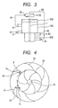
- FIG. 3 shows a pressurization pump 100 using a centrifugal pump, a Francis turbine 200 (hydro turbine) as an energy recovery apparatus disposed below the pressurization pump 100 to recover power energy, a rotation shaft 1 common to the pressurization pump 100 and hydro turbine 200, an axial thrust support device 300 for supporting the axial thrust of rotation of both the pump and turbine, and a high-pressure reverse osmosis membrane unit 50 for removing impurity from raw water including impurity such as salt through an osmosis membrane process.
- a pressurization pump 100 using a centrifugal pump a Francis turbine 200 (hydro turbine) as an energy recovery apparatus disposed below the pressurization pump 100 to recover power energy
- a rotation shaft 1 common to the pressurization pump 100 and hydro turbine 200
- an axial thrust support device 300 for supporting the axial thrust of rotation of both the pump and turbine
- a high-pressure reverse osmosis membrane unit 50 for removing impurity from raw water including impurity such as salt through an os
- the rotation shaft 1 rotates, raw water 51 including impurity such as salt is drawn from a pump inlet 3, discharged from an outlet 8, and supplied to the high-pressure reverse osmosis membrane unit 50.
- the high-pressure reverse osmosis membrane unit 50 applies a reverse osmosis membrane process to the raw water 51 including impurity such as salt, and discharges permeate water 52 from which impurity such as salt has been removed.
- high-pressure concentrated water 53 which has been left by the reverse osmosis membrane process, is supplied to a turbine inlet of the turbine 200, and recovered as part of energy for driving (rotating) this turbine. Concentrated water 54 from which energy has been recovered in the turbine section is then discarded from a turbine outlet 36 outside the system.
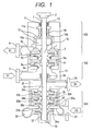
- Embodiment 1 of the pump system of the present invention is explained in reference to a cross section of Fig. 1 .
- the rotation shaft 1 common to the centrifugal pressurization pump 100 and Francis turbine 200 is a vertical shaft
- the pressurization pump 100 is disposed above the Francis turbine (hydro turbine) 200 which recovers energy
- the axial thrust support device 300 supports an axial thrust acting on pump impellers of the pressurization pump 100 and an axial thrust acting on turbine impellers of the hydro turbine 200.
- the rotation shaft 1 is a rotation shaft common to the pressurization pump 100, turbine 200, and axial thrust support device 300, and described as a shaft 1a in the pressurization pump and as a shaft 1b in the turbine.
- the pressurization pump 100 includes, in a pump casing 13, two stages of centrifugal impellers 4a (first stage pump impeller) and 4b (second stage pump impeller), and diffusers 5a and 5b disposed to respective peripheral outlets of the pump impellers 4a and 4b.
- the pump inlet 3 in communication with the impeller 4a is provided to a lower portion of the casing 13.
- the outlet 8 in communication with the impeller 4b is provided to an upper portion of the casing 13.
- a static fluid path 6 having a square bracket shape connects between the first and second stage impellers.
- Return vanes 6a are disposed radially from the shaft center in the radial direction to straighten a flow to the next stage impeller.
- multistage pump impellers (two stage impellers in this Embodiment) are provided to a pump, a net pump head of which is high to be about 500 to 800 m.
- Pump driving power is applied to the pump rotation shaft 1a via a shaft coupling 2 from, e.g., an electric motor (not shown).
- the pressurization pump 100 draws the seawater 51 as raw water from the inlet 3.
- a pressure of the seawater 51 is raised at the first and second stage pump impellers 4a and 4b.
- the diffusers 5a and 5b change kinetic energy of the flow to pressure energy.
- the seawater 51 flows from the first stage to second stage through the static fluid path 6 having a square bracket shape, and the flow to the next stage is straightened by the return vanes 6a.
- the flow which has come out of the second stage impeller 4b is gathered to a concentric space 7 via the diffuser 5b, and discharged from the outlet 8.
- the pump shaft 1a is supported radially by a bearing 9a disposed to a lower end of the pump inlet 3 and an upper bearing 9b of the pump shaft 1a.
- These bearings are submerged bearings formed of a self-lubricating material (for example, a Poly-Ether-Ether-Ketone (PEEK) resin material).
- PEEK Poly-Ether-Ether-Ketone
- Each bearing can function as a bearing by a property of the self-lubricating material and by lubrication of a self lubricant.
- a great downward axial thrust generated in the pump impellers 4a and 4b at the time of rotation of the pump is balanced by an automatic axial thrust balancing device 10 not to act the axial thrust on a thrust bearing 11.
- the thrust bearing 11 may be a bearing for supporting a self-weight of the pump rotor when the pump is at rest.
- a ball bearing is used as the thrust bearing 11, an inner ring of the ball bearing is secured to the shaft 1, and the outer ring is fitted movably in the axial direction.
- a stationary stopper 11a on a lower side of a case of the bearing supports the self-weight of the pump rotor via the ball bearing 11.
- a shaft seal for a penetration portion of the pump shaft 1a to the atmosphere a leakage flow largely depressurized from a discharge pressure of the pump through the automatic axial thrust balancing device 10 is sealed by a shaft seal 12 such as a gland seal. The leakage flow is returned to the pump inlet 3 via piping (not shown).
- the axial thrust support device 300 includes the axial thrust balancing device 10 and thrust bearing 11, and is provided to an upper portion of the rotation shaft 1 in the pump casing 13.
- Equation 1 Ns shows a hydro turbine specific speed
- N shows hydro turbine revolutions per minute (rpm)
- Q shows Hydro turbine flow rate (m 3 /min)
- H shows an effective head (m).
- rpm hydro turbine revolutions per minute
- m Hydro turbine flow rate
- m Hydro turbine flow rate
- H an effective head
- the turbine impellers including a turbine impeller 34a (the first stage turbine impeller), a turbine impeller 34b (the second stage turbine impeller), and a turbine impeller 34c (the third stage turbine impeller), are coaxially disposed within the turbine casing 39 opposite the pump impellers 4a and 4b (facing the impellers to each other).
- Guide vanes 33a (the first stage guide vanes), 33b (the second stage guide vanes), and 33c (the third stage guide vanes) are disposed to respective guide portions to the turbine impellers to straighten a fluid flow flowing to each turbine impeller 34 and to regulate a direction of the flow.
- a water path 35 is interposed between each stage to provide return vanes 35a and return vanes 35b.
- the return vanes prevent the flow which has come out of each turbine impeller from swirling, and straighten the flow.
- the turbine inlet 31 in communication with the turbine impeller 34a is disposed to a lower portion of the casing 39.
- the turbine outlet 36 in communication with the turbine impeller 34c is disposed to an upper portion of the casing 39.
- the turbine 200 is mounted below the pressurization pump 100 to position the pump inlet 3 of the pump casing 13 and the turbine outlet 36 of the turbine casing 39 adjacently to one another. In such a way, a specific seal mechanism is unnecessary for a connection portion between the pump inlet 3 of the pressurization pump 100 and the turbine outlet 36 of the turbine 200, because the pump inlet 3 and the turbine outlet 36 are both on the low pressure side and have a low differential pressure therebetween.
- the water 53 is straightened and a direction of the flow of the water 53 is regulated.
- the water 53 flows into the first stage impeller 34a to change energy of one third of the effective head into mechanical power.
- the water 53 flows through the return vanes 35a and water path 35 and flows into the second stage impeller 34b through the second stage guide vanes 33b.
- the water 53 flows through the return vanes 35b and water path 35 and flows into the third stage impeller 34c through the third stage guide vanes 33b.
- the energy of the effective head is changed at the third stage impeller 34 c , the water 53 is discharged from the turbine outlet 36 outside the turbine.
- Equation 2 D C ⁇ 2 ⁇ gH N 60 ⁇ ⁇
- Equation 2 D shows an outer diameter of a turbine impeller, C shows a peripheral velocity coefficient of a turbine impeller (dimensionless number) , H shows an effective head per one stage (m), and N shows revolutions per minute (rpm) of a turbine impeller.
- An axial thrust F is calculable by Equation (3). Equation 3 F ⁇ n ⁇ ⁇ 4 ⁇ D 2 ⁇ ⁇ ⁇ gH
- Equation 3 F shows an axial thrust (N), n shows the number of hydro turbine stages, ⁇ shows a density (kg/m 3 ) of seawater, g shows a gravitational acceleration (m/s2), and H shows an effective head per one hydro turbine stage. Since the number of the stages of the turbine impellers is greater than that of the pressurization pump, an effective head per one turbine impeller is smaller than a net pump head per one stage of the pump. At the same time, given that a peripheral velocity coefficient of the turbine impeller is usually smaller than that of the pump impeller, an outer diameter of the turbine impeller is smaller than that of the pump impeller. Therefore, as shown in Equation (3), since the turbine and pump are generally the same in (n*H), an axial thrust of the turbine 200 is smaller than an outer diameter of the pump impeller due to an outer diameter of the turbine impeller.
- a downward axial thrust of the pump impeller is partially cancelled by an upward axial thrust of the turbine impeller, and thus becomes smaller.
- This remaining axis thrust which has been made smaller, can be balanced by the axial thrust balancing device 10 of the pump.
- the turbine shaft 1b is supported by a bearing 37 on a lower end of the turbine shaft 1b and a pump bearing 9a.
- these bearings are submerged bearings as well as the bearings 9a and 9b of the pump, a bearing lubrication device is unnecessary to achieve easy downsizing and maintenance of the system.
- a flow rate of the concentrated water 53 in the turbine 200 is obtained by subtracting a reverse osmosis membrane permeate flow from a pump water supply, namely about forty to sixty percent of the pump water supply, and smaller than the pump water supply.
- a flow direction (angle) of each guide vane is regulated.
- Fig. 4 is a view explaining relationship between an angle of each turbine guide vane 33 relative to the turbine impeller 34 and an angle of each diffuser 5 of the pump.
- the diffusers 5 (only part of which is shown) are shown on the assumption that the same impeller as the pump impeller is used as the turbine impeller 34.
- relationship between these angles is ⁇ t ⁇ p.
- the concentrated water is guided to the turbine impeller 34 generally at a right angle to transfer energy efficiently even when an amount of the concentrated water guided to the turbine guide vanes 33 is small. Therefore, a specific speed of the turbine impeller can maintain higher than that of the pump impeller to recover energy efficiently.
- the multistage centrifugal pump as the pressurization pump for the reverse osmosis membrane and the multistage Francis hydro turbine as the concentrated water energy recovery apparatus and by positioning their impellers on a single shaft opposite each other, the compact, efficient, reliable, efficient, high-reliability, low-cost pump system having the energy recovery apparatus is realizable.
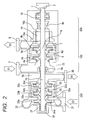
- Embodiment 2 is explained in reference to Fig. 2 .
- Embodiment 2 is different from Embodiment 1 only in that a rotation shaft is horizontal and an axial thrust support device includes a balance drum 14 and a thrust bearing 15.
- the balance drum 14 supports axial thrusts of the pump and hydro turbine by use of a difference of pressures respectively acting on front and back surfaces 14a and 14b of the drum 14. In comparison with the axial thrust balancing device of Embodiment 1, the balance drum 14 has no automatic regulation function. Therefore, it is difficult to balance the axial thrusts completely. The remaining thrust is supported by the thrust bearing 15.
- Embodiment 1 since the axial thrust of the hydro turbine impellers and pump impellers is partially canceled to become small, the same advantage as Embodiment 1 is provided in which an outer diameter of the balance drum 14 can be designed small and leakage loss can be reduced.
- the thrust bearing 15 uses a material (for example, a Poly-Ether-Ether-Ketone resin (PEEK)) having self-lubricating function, a lubrication device is unnecessary, reducing a cost of the bearing device. Therefore, also in Embodiment 2, like in Embodiment 1, a compact, efficient, reliable, low-cost pump system having a power recovery apparatus can be provided.
- the vertical shaft structure uses the balancing disc device
- the horizontal shaft structure uses the balance drum and the thrust bearing, but the vertical shaft structure may use the balance drum and the thrust bearing, and the horizontal shaft structure may use the balancing disc device.
- the focus of the present invention is to provide a reliable, low-cost axial thrust support device which supports axial thrusts of the pump and hydro turbine and which is shared by the pump and hydro turbine.
- the above embodiments are applicable for a pump, which is the heart of, for example, a desalination plant using a reverse osmosis membrane.
- Particularly the embodiments can provide a pump having an energy recovery apparatus preferable for a large capacity desalination plant.
Landscapes
- Engineering & Computer Science (AREA)
- Mechanical Engineering (AREA)
- General Engineering & Computer Science (AREA)
- Chemical & Material Sciences (AREA)
- Combustion & Propulsion (AREA)
- Separation Using Semi-Permeable Membranes (AREA)
- Structures Of Non-Positive Displacement Pumps (AREA)
- Hydraulic Turbines (AREA)
- Other Liquid Machine Or Engine Such As Wave Power Use (AREA)
Claims (6)
- Pumpensystem mit einer Energierückgewinnungsvorrichtung, wobei das Pumpensystem aufweist:eine Druckerzeugungspumpe (100) mit einem Gehäuse (13) mit einem Einlass (3), undeine Wasserturbine (200), die als die Energierückgewinnungsvorrichtung verwendet wird, wobei die Wasserturbine (200) ein Gehäuse (39) mit einem Auslass aufweist, wobei die Energierückgewinnungsvorrichtung Energie von unter hohem Druck stehendem konzentrierten Abwasser rückgewinnt, um die Energie als Antriebskraft für die Druckerzeugungspumpe (100) zu nutzen, wenn Brauchwasser (51), das durch die Druckerzeugungspumpe (100) druckbeauf schlagt wird, mit einer Umkehrosmosemembran (50) gefiltert wird,wobei die Wasserturbine (200) mehrstufige Turbinenschaufelräder (34a, 34b, 34c) aufweist, die koaxial zu einer Welle (1) der Druckerzeugungspumpe (100) angeordnet sind, wobei die Turbinenschaufelräder (34a, 34b, 34c) gegenüber den Pumpenschaufelrädern (4a, 4b) der Druckerzeugungspumpe (100) angeordnet sind,dadurch gekennzeichnet, dassdie Wasserturbine (200) unterhalb der Druckerzeugungspumpe (100) montiert ist, um den Pumpeneinlass (13) angrenzend an den Turbinenauslass (36) zu positionieren, und wobei die Anzahl der Stufen der Schaufelräder (34a, 34b, 34c) der Wasserturbine (200) wenigstens gleich oder größer als die Anzahl der Schaufelräder der Pumpe (100) gewählt ist.
- Pumpensystem nach Anspruch 1, das ferner eine Axialschubaufnahmevorrichtung (300) aufweist, die einen axialen Schub der Turbinenschaufelräder (34a, 34b, 34c) und einen axialen Schub der Pumpenschaufelräder (4a, 4b) aufnimmt.
- Pumpensystem nach Anspruch 1 oder 2, wobei die Druckerzeugungspumpe (100) und die Wasserturbine (200) so angeordnet sind, dass eine Einlassseite (Niederdruckseite) der Druckerzeugungspumpe (100) und eine Auslassseite (Niederdruckseite) der Wasserturbine (200) benachbart zueinander angeordnet sind.
- Pumpensystem nach einem der Ansprüche 1 bis 3,
wobei die Welle (1) für die Druckerzeugungspumpe (100) und die Wasserturbine (200) von einem eingetauchten Radiallager (11) getragen wird. - Pumpensystem nach Anspruch 2,
wobei die Axialschubaufnahmevorrichtung (300) eine Axialschubausgleichsvorrichtung (10) ist, die eine Ausgleichsscheibe verwendet. - Pumpensystem nach einem der Ansprüche 1 bis 5,
wobei ein Ende der Welle (1) für die Druckerzeugungspumpe (100) und die Wasserturbine (200) einen nicht abgedichteten Aufbau aufweist, der eine Endabdeckung (38) verwendet.
Applications Claiming Priority (1)
| Application Number | Priority Date | Filing Date | Title |
|---|---|---|---|
| JP2009224873A JP5344697B2 (ja) | 2009-09-29 | 2009-09-29 | エネルギー回収装置を備えたポンプ |
Publications (4)
| Publication Number | Publication Date |
|---|---|
| EP2302201A2 EP2302201A2 (de) | 2011-03-30 |
| EP2302201A3 EP2302201A3 (de) | 2013-03-13 |
| EP2302201B1 true EP2302201B1 (de) | 2014-04-02 |
| EP2302201B8 EP2302201B8 (de) | 2014-05-14 |
Family
ID=42984461
Family Applications (1)
| Application Number | Title | Priority Date | Filing Date |
|---|---|---|---|
| EP10181357.4A Not-in-force EP2302201B8 (de) | 2009-09-29 | 2010-09-28 | Pumpe-System mit Rückgewinnung von Energie |
Country Status (4)
| Country | Link |
|---|---|
| EP (1) | EP2302201B8 (de) |
| JP (1) | JP5344697B2 (de) |
| KR (1) | KR101222384B1 (de) |
| CN (1) | CN102032194A (de) |
Families Citing this family (28)
| Publication number | Priority date | Publication date | Assignee | Title |
|---|---|---|---|---|
| IT1399881B1 (it) * | 2010-05-11 | 2013-05-09 | Nuova Pignone S R L | Configurazione di tamburo di bilanciamento per rotori di compressore |
| CN102734042B (zh) * | 2011-04-05 | 2015-04-15 | 张意立 | 一种两层双蜗壳能量传递执行器 |
| CN102312840A (zh) * | 2011-09-02 | 2012-01-11 | 南方泵业股份有限公司 | 一种高压多级离心泵 |
| CN102374101A (zh) * | 2011-09-26 | 2012-03-14 | 江苏合得合能环保科技发展有限公司 | 一种防爆水力增压泵 |
| CN103306879A (zh) * | 2013-07-09 | 2013-09-18 | 江苏风盛海水淡化科技有限公司 | 机电一体化式透平式能量回收装置总成 |
| WO2015023636A1 (en) * | 2013-08-13 | 2015-02-19 | Schlumberger Canada Limited | Electric submersible pump with fluid coupling |
| ITCO20130069A1 (it) * | 2013-12-18 | 2015-06-19 | Nuovo Pignone Srl | Compressore centrifugo multistadio |
| CN104179629B (zh) * | 2014-08-31 | 2016-05-04 | 张意立 | 一种卡箍锌合金氧化铝压力转换机泵 |
| CN104179628B (zh) * | 2014-08-31 | 2016-05-04 | 张意立 | 一种焊接头钛合金氮化硅压力交换器 |
| CN104190257B (zh) * | 2014-08-31 | 2016-01-13 | 张意立 | 一种内螺纹铬合金氧化锆能量再用机泵 |
| EP3009181A1 (de) * | 2014-09-29 | 2016-04-20 | Sulzer Management AG | Umkehrosmosesystem |
| JP6420701B2 (ja) * | 2015-03-24 | 2018-11-07 | 株式会社荏原製作所 | ポンプ |
| JP2017048718A (ja) * | 2015-09-02 | 2017-03-09 | 株式会社日立産機システム | 水車一体型ポンプ及び水蓄熱空調設備 |
| NO20151169A1 (en) * | 2015-09-11 | 2017-03-13 | Qrrnt As | A system for treating a liquid medium by reverse osmosis |
| CN105736393B (zh) * | 2016-01-28 | 2019-08-20 | 杭州大路实业有限公司 | 一种电动和汽轮双驱动的循环水泵 |
| CN105604955A (zh) * | 2016-01-29 | 2016-05-25 | 上海福思特流体机械有限公司 | 一种立式两级离心煤浆泵 |
| CN105735424A (zh) * | 2016-03-10 | 2016-07-06 | 池泉 | 一种给水系统 |
| WO2018148542A1 (en) | 2017-02-09 | 2018-08-16 | Bergstrom Robert A | Brine dispersal system |
| US10801512B2 (en) | 2017-05-23 | 2020-10-13 | Vector Technologies Llc | Thrust bearing system and method for operating the same |
| US11085457B2 (en) | 2017-05-23 | 2021-08-10 | Fluid Equipment Development Company, Llc | Thrust bearing system and method for operating the same |
| CN107237758B (zh) * | 2017-07-19 | 2024-02-27 | 赛腾机电科技(常州)有限公司 | 液力增压和余压回收装置 |
| CN109340105B (zh) * | 2018-10-21 | 2025-05-30 | 张玉新 | 海水淡化高压泵 |
| CN109469629A (zh) * | 2018-12-08 | 2019-03-15 | 烟台龙港泵业股份有限公司 | 一种带能量回收透平的高压泵 |
| CN110080989A (zh) * | 2019-05-20 | 2019-08-02 | 大连深蓝泵业有限公司 | 同轴式对称布置多级液力透平直驱泵及其使用方法 |
| CN110469536A (zh) * | 2019-07-19 | 2019-11-19 | 河北科技大学 | 透平增压泵润滑结构 |
| CN110469513A (zh) * | 2019-07-19 | 2019-11-19 | 河北科技大学 | 透平增压泵 |
| CN112392730A (zh) * | 2020-01-22 | 2021-02-23 | 陈科 | 一种带轴开中分便拆结构的化工泵 |
| CN112814918B (zh) * | 2020-12-30 | 2023-01-20 | 东方电气集团东方汽轮机有限公司 | 一种立式汽轮给水泵同轴一体转子结构 |
Family Cites Families (15)
| Publication number | Priority date | Publication date | Assignee | Title |
|---|---|---|---|---|
| US4230564A (en) * | 1978-07-24 | 1980-10-28 | Keefer Bowie | Rotary reverse osmosis apparatus and method |
| JPS60159301A (ja) * | 1984-01-27 | 1985-08-20 | Mitsubishi Heavy Ind Ltd | ポンプ及び動力回収タ−ビン装置 |
| DE3510160A1 (de) * | 1985-03-21 | 1986-09-25 | Hellmut 7923 Königsbronn Weinrich | Druckwasserversorgungsanlage zur wasserentsalzung |
| JPS6291693A (ja) * | 1985-10-16 | 1987-04-27 | Nikkiso Co Ltd | 動力回収形キヤンドモ−タポンプ |
| JP3121164B2 (ja) * | 1993-01-19 | 2000-12-25 | オルガノ株式会社 | 膜分離装置 |
| CN1050103C (zh) * | 1993-03-05 | 2000-03-08 | 北京市西城区新开通用试验厂 | 用于海船的数控海水淡化装置 |
| KR940022953U (ko) * | 1993-03-31 | 1994-10-20 | 다단원심펌프의 축추력 평형장치 | |
| IT1272452B (it) * | 1993-05-25 | 1997-06-23 | Lowara Spa | Apparecchiatura costituita da pompa multistadio e turbina assialmente integrate, particolarmente adatta per il recupero di energia nei processi di trattamento per osmosi inversa delle acque di scarico industriali e simili |
| MX245299B (en) * | 1998-02-27 | 2007-04-24 | Large tube assemblies for reverse osmosis | |
| JP2000145681A (ja) * | 1998-11-10 | 2000-05-26 | Ebara Corp | 水車駆動ターボポンプ |
| KR100497124B1 (ko) * | 2002-12-30 | 2005-06-28 | 코오롱건설주식회사 | 해수 담수화 설비의 해수 2차 가압장치 |
| KR100672844B1 (ko) * | 2005-02-04 | 2007-01-22 | 주식회사 그린웰 | 에너지 저감형 해수담수화 시스템 |
| JP2006316628A (ja) * | 2005-05-10 | 2006-11-24 | Hitachi Plant Technologies Ltd | 液化ガス用ポンプ装置 |
| US7318422B2 (en) * | 2005-07-27 | 2008-01-15 | Walbro Engine Management, L.L.C. | Fluid pump assembly |
| CN201292269Y (zh) * | 2008-11-14 | 2009-08-19 | 中国人民解放军海军节能技术研究中心 | 膜分离装置,特别是反渗透海水淡化装置 |
-
2009
- 2009-09-29 JP JP2009224873A patent/JP5344697B2/ja not_active Expired - Fee Related
-
2010
- 2010-09-17 CN CN2010102877912A patent/CN102032194A/zh active Pending
- 2010-09-28 KR KR1020100093494A patent/KR101222384B1/ko not_active Expired - Fee Related
- 2010-09-28 EP EP10181357.4A patent/EP2302201B8/de not_active Not-in-force
Also Published As
| Publication number | Publication date |
|---|---|
| KR101222384B1 (ko) | 2013-01-15 |
| CN102032194A (zh) | 2011-04-27 |
| EP2302201A3 (de) | 2013-03-13 |
| EP2302201A2 (de) | 2011-03-30 |
| KR20110035920A (ko) | 2011-04-06 |
| JP5344697B2 (ja) | 2013-11-20 |
| JP2011074785A (ja) | 2011-04-14 |
| EP2302201B8 (de) | 2014-05-14 |
Similar Documents
| Publication | Publication Date | Title |
|---|---|---|
| EP2302201B1 (de) | Pumpe-System mit Rückgewinnung von Energie | |
| CN102606484A (zh) | 一种核电站用的上充泵 | |
| CA2790252C (en) | Improved pump | |
| US20100119363A1 (en) | High-Efficiency, Multi-Stage Centrifugal Pump and Method of Assembly | |
| US20130088014A1 (en) | Water turbine | |
| KR20090100432A (ko) | 바람 흐름 또는 물 흐름에 의해서 구동되는 에너지 발생 장치 | |
| JP2010281274A (ja) | 風力ポンプ | |
| CN201599199U (zh) | 1000mw核电站用核二级泵电动辅助给水泵 | |
| CN102022384B (zh) | 矿潜泵的一种硬质合金滑动轴承引水冷却润滑系统 | |
| CN110630526A (zh) | 一种新型潜水渣浆泵 | |
| US20130302187A1 (en) | Pump Turbine Installation | |
| EP4286681B1 (de) | Energiespeichersystem | |
| CN201891681U (zh) | 矿潜泵的一种硬质合金滑动轴承引水冷却润滑系统 | |
| RU2435075C2 (ru) | Насосный агрегат и насосная система, в которой он используется | |
| CN101793254A (zh) | 单级卧式自动平衡离心密封泵 | |
| CN201137583Y (zh) | 具有护管式清水润滑轴承结构的立式水泵 | |
| RU116920U1 (ru) | Многоступенчатый центробежный насос с предвключенным (бустерным) устройством | |
| EP3810314B1 (de) | Zentrifugalpumpe | |
| RU104649U1 (ru) | Насосный агрегат для подачи питательной воды в парогенераторы энергоблоков аэс | |
| CN102072162A (zh) | 桨式自动平衡离心密封泵 | |
| CN202065230U (zh) | 一种桨式自动平衡离心密封泵 | |
| Garbus et al. | Types of pumps | |
| CN200952488Y (zh) | 单级卧式自动平衡离心密封泵 | |
| CN201661471U (zh) | 核电站离心密封给水泵 | |
| KR200333280Y1 (ko) | 하방토출식 원심펌프 |
Legal Events
| Date | Code | Title | Description |
|---|---|---|---|
| PUAI | Public reference made under article 153(3) epc to a published international application that has entered the european phase |
Free format text: ORIGINAL CODE: 0009012 |
|
| 17P | Request for examination filed |
Effective date: 20110127 |
|
| AK | Designated contracting states |
Kind code of ref document: A2 Designated state(s): AL AT BE BG CH CY CZ DE DK EE ES FI FR GB GR HR HU IE IS IT LI LT LU LV MC MK MT NL NO PL PT RO SE SI SK SM TR |
|
| AX | Request for extension of the european patent |
Extension state: BA ME RS |
|
| PUAL | Search report despatched |
Free format text: ORIGINAL CODE: 0009013 |
|
| RIC1 | Information provided on ipc code assigned before grant |
Ipc: F03B 3/02 20060101AFI20130125BHEP |
|
| AK | Designated contracting states |
Kind code of ref document: A3 Designated state(s): AL AT BE BG CH CY CZ DE DK EE ES FI FR GB GR HR HU IE IS IT LI LT LU LV MC MK MT NL NO PL PT RO SE SI SK SM TR |
|
| AX | Request for extension of the european patent |
Extension state: BA ME RS |
|
| GRAP | Despatch of communication of intention to grant a patent |
Free format text: ORIGINAL CODE: EPIDOSNIGR1 |
|
| INTG | Intention to grant announced |
Effective date: 20131108 |
|
| GRAS | Grant fee paid |
Free format text: ORIGINAL CODE: EPIDOSNIGR3 |
|
| GRAA | (expected) grant |
Free format text: ORIGINAL CODE: 0009210 |
|
| AK | Designated contracting states |
Kind code of ref document: B1 Designated state(s): AL AT BE BG CH CY CZ DE DK EE ES FI FR GB GR HR HU IE IS IT LI LT LU LV MC MK MT NL NO PL PT RO SE SI SK SM TR |
|
| REG | Reference to a national code |
Ref country code: GB Ref legal event code: FG4D |
|
| REG | Reference to a national code |
Ref country code: AT Ref legal event code: REF Ref document number: 660295 Country of ref document: AT Kind code of ref document: T Effective date: 20140415 Ref country code: CH Ref legal event code: EP |
|
| RAP2 | Party data changed (patent owner data changed or rights of a patent transferred) |
Owner name: HITACHI, LTD. |
|
| REG | Reference to a national code |
Ref country code: IE Ref legal event code: FG4D |
|
| REG | Reference to a national code |
Ref country code: DE Ref legal event code: R096 Ref document number: 602010014749 Country of ref document: DE Effective date: 20140515 |
|
| REG | Reference to a national code |
Ref country code: AT Ref legal event code: MK05 Ref document number: 660295 Country of ref document: AT Kind code of ref document: T Effective date: 20140402 |
|
| REG | Reference to a national code |
Ref country code: NL Ref legal event code: VDEP Effective date: 20140402 |
|
| REG | Reference to a national code |
Ref country code: LT Ref legal event code: MG4D |
|
| PG25 | Lapsed in a contracting state [announced via postgrant information from national office to epo] |
Ref country code: GR Free format text: LAPSE BECAUSE OF FAILURE TO SUBMIT A TRANSLATION OF THE DESCRIPTION OR TO PAY THE FEE WITHIN THE PRESCRIBED TIME-LIMIT Effective date: 20140703 Ref country code: NO Free format text: LAPSE BECAUSE OF FAILURE TO SUBMIT A TRANSLATION OF THE DESCRIPTION OR TO PAY THE FEE WITHIN THE PRESCRIBED TIME-LIMIT Effective date: 20140702 Ref country code: IS Free format text: LAPSE BECAUSE OF FAILURE TO SUBMIT A TRANSLATION OF THE DESCRIPTION OR TO PAY THE FEE WITHIN THE PRESCRIBED TIME-LIMIT Effective date: 20140802 Ref country code: BG Free format text: LAPSE BECAUSE OF FAILURE TO SUBMIT A TRANSLATION OF THE DESCRIPTION OR TO PAY THE FEE WITHIN THE PRESCRIBED TIME-LIMIT Effective date: 20140702 Ref country code: LT Free format text: LAPSE BECAUSE OF FAILURE TO SUBMIT A TRANSLATION OF THE DESCRIPTION OR TO PAY THE FEE WITHIN THE PRESCRIBED TIME-LIMIT Effective date: 20140402 Ref country code: CZ Free format text: LAPSE BECAUSE OF FAILURE TO SUBMIT A TRANSLATION OF THE DESCRIPTION OR TO PAY THE FEE WITHIN THE PRESCRIBED TIME-LIMIT Effective date: 20140402 Ref country code: NL Free format text: LAPSE BECAUSE OF FAILURE TO SUBMIT A TRANSLATION OF THE DESCRIPTION OR TO PAY THE FEE WITHIN THE PRESCRIBED TIME-LIMIT Effective date: 20140402 Ref country code: FI Free format text: LAPSE BECAUSE OF FAILURE TO SUBMIT A TRANSLATION OF THE DESCRIPTION OR TO PAY THE FEE WITHIN THE PRESCRIBED TIME-LIMIT Effective date: 20140402 Ref country code: CY Free format text: LAPSE BECAUSE OF FAILURE TO SUBMIT A TRANSLATION OF THE DESCRIPTION OR TO PAY THE FEE WITHIN THE PRESCRIBED TIME-LIMIT Effective date: 20140402 |
|
| PG25 | Lapsed in a contracting state [announced via postgrant information from national office to epo] |
Ref country code: LV Free format text: LAPSE BECAUSE OF FAILURE TO SUBMIT A TRANSLATION OF THE DESCRIPTION OR TO PAY THE FEE WITHIN THE PRESCRIBED TIME-LIMIT Effective date: 20140402 Ref country code: ES Free format text: LAPSE BECAUSE OF FAILURE TO SUBMIT A TRANSLATION OF THE DESCRIPTION OR TO PAY THE FEE WITHIN THE PRESCRIBED TIME-LIMIT Effective date: 20140402 Ref country code: PL Free format text: LAPSE BECAUSE OF FAILURE TO SUBMIT A TRANSLATION OF THE DESCRIPTION OR TO PAY THE FEE WITHIN THE PRESCRIBED TIME-LIMIT Effective date: 20140402 Ref country code: AT Free format text: LAPSE BECAUSE OF FAILURE TO SUBMIT A TRANSLATION OF THE DESCRIPTION OR TO PAY THE FEE WITHIN THE PRESCRIBED TIME-LIMIT Effective date: 20140402 Ref country code: HR Free format text: LAPSE BECAUSE OF FAILURE TO SUBMIT A TRANSLATION OF THE DESCRIPTION OR TO PAY THE FEE WITHIN THE PRESCRIBED TIME-LIMIT Effective date: 20140402 Ref country code: SE Free format text: LAPSE BECAUSE OF FAILURE TO SUBMIT A TRANSLATION OF THE DESCRIPTION OR TO PAY THE FEE WITHIN THE PRESCRIBED TIME-LIMIT Effective date: 20140402 |
|
| PG25 | Lapsed in a contracting state [announced via postgrant information from national office to epo] |
Ref country code: PT Free format text: LAPSE BECAUSE OF FAILURE TO SUBMIT A TRANSLATION OF THE DESCRIPTION OR TO PAY THE FEE WITHIN THE PRESCRIBED TIME-LIMIT Effective date: 20140804 |
|
| REG | Reference to a national code |
Ref country code: DE Ref legal event code: R097 Ref document number: 602010014749 Country of ref document: DE |
|
| PG25 | Lapsed in a contracting state [announced via postgrant information from national office to epo] |
Ref country code: RO Free format text: LAPSE BECAUSE OF FAILURE TO SUBMIT A TRANSLATION OF THE DESCRIPTION OR TO PAY THE FEE WITHIN THE PRESCRIBED TIME-LIMIT Effective date: 20140402 Ref country code: BE Free format text: LAPSE BECAUSE OF FAILURE TO SUBMIT A TRANSLATION OF THE DESCRIPTION OR TO PAY THE FEE WITHIN THE PRESCRIBED TIME-LIMIT Effective date: 20140402 Ref country code: EE Free format text: LAPSE BECAUSE OF FAILURE TO SUBMIT A TRANSLATION OF THE DESCRIPTION OR TO PAY THE FEE WITHIN THE PRESCRIBED TIME-LIMIT Effective date: 20140402 Ref country code: DK Free format text: LAPSE BECAUSE OF FAILURE TO SUBMIT A TRANSLATION OF THE DESCRIPTION OR TO PAY THE FEE WITHIN THE PRESCRIBED TIME-LIMIT Effective date: 20140402 Ref country code: SK Free format text: LAPSE BECAUSE OF FAILURE TO SUBMIT A TRANSLATION OF THE DESCRIPTION OR TO PAY THE FEE WITHIN THE PRESCRIBED TIME-LIMIT Effective date: 20140402 |
|
| PLBE | No opposition filed within time limit |
Free format text: ORIGINAL CODE: 0009261 |
|
| STAA | Information on the status of an ep patent application or granted ep patent |
Free format text: STATUS: NO OPPOSITION FILED WITHIN TIME LIMIT |
|
| 26N | No opposition filed |
Effective date: 20150106 |
|
| PG25 | Lapsed in a contracting state [announced via postgrant information from national office to epo] |
Ref country code: IT Free format text: LAPSE BECAUSE OF FAILURE TO SUBMIT A TRANSLATION OF THE DESCRIPTION OR TO PAY THE FEE WITHIN THE PRESCRIBED TIME-LIMIT Effective date: 20140402 |
|
| REG | Reference to a national code |
Ref country code: DE Ref legal event code: R097 Ref document number: 602010014749 Country of ref document: DE Effective date: 20150106 |
|
| PG25 | Lapsed in a contracting state [announced via postgrant information from national office to epo] |
Ref country code: MC Free format text: LAPSE BECAUSE OF FAILURE TO SUBMIT A TRANSLATION OF THE DESCRIPTION OR TO PAY THE FEE WITHIN THE PRESCRIBED TIME-LIMIT Effective date: 20140402 Ref country code: LU Free format text: LAPSE BECAUSE OF FAILURE TO SUBMIT A TRANSLATION OF THE DESCRIPTION OR TO PAY THE FEE WITHIN THE PRESCRIBED TIME-LIMIT Effective date: 20140928 |
|
| REG | Reference to a national code |
Ref country code: CH Ref legal event code: PL |
|
| REG | Reference to a national code |
Ref country code: IE Ref legal event code: MM4A |
|
| PG25 | Lapsed in a contracting state [announced via postgrant information from national office to epo] |
Ref country code: CH Free format text: LAPSE BECAUSE OF NON-PAYMENT OF DUE FEES Effective date: 20140930 Ref country code: LI Free format text: LAPSE BECAUSE OF NON-PAYMENT OF DUE FEES Effective date: 20140930 Ref country code: SI Free format text: LAPSE BECAUSE OF FAILURE TO SUBMIT A TRANSLATION OF THE DESCRIPTION OR TO PAY THE FEE WITHIN THE PRESCRIBED TIME-LIMIT Effective date: 20140402 |
|
| REG | Reference to a national code |
Ref country code: FR Ref legal event code: PLFP Year of fee payment: 6 |
|
| PG25 | Lapsed in a contracting state [announced via postgrant information from national office to epo] |
Ref country code: IE Free format text: LAPSE BECAUSE OF NON-PAYMENT OF DUE FEES Effective date: 20140928 |
|
| PGFP | Annual fee paid to national office [announced via postgrant information from national office to epo] |
Ref country code: DE Payment date: 20150922 Year of fee payment: 6 Ref country code: GB Payment date: 20150923 Year of fee payment: 6 |
|
| PGFP | Annual fee paid to national office [announced via postgrant information from national office to epo] |
Ref country code: FR Payment date: 20150811 Year of fee payment: 6 |
|
| PG25 | Lapsed in a contracting state [announced via postgrant information from national office to epo] |
Ref country code: SM Free format text: LAPSE BECAUSE OF FAILURE TO SUBMIT A TRANSLATION OF THE DESCRIPTION OR TO PAY THE FEE WITHIN THE PRESCRIBED TIME-LIMIT Effective date: 20140402 |
|
| PG25 | Lapsed in a contracting state [announced via postgrant information from national office to epo] |
Ref country code: MT Free format text: LAPSE BECAUSE OF FAILURE TO SUBMIT A TRANSLATION OF THE DESCRIPTION OR TO PAY THE FEE WITHIN THE PRESCRIBED TIME-LIMIT Effective date: 20140402 |
|
| PG25 | Lapsed in a contracting state [announced via postgrant information from national office to epo] |
Ref country code: TR Free format text: LAPSE BECAUSE OF FAILURE TO SUBMIT A TRANSLATION OF THE DESCRIPTION OR TO PAY THE FEE WITHIN THE PRESCRIBED TIME-LIMIT Effective date: 20140402 Ref country code: HU Free format text: LAPSE BECAUSE OF FAILURE TO SUBMIT A TRANSLATION OF THE DESCRIPTION OR TO PAY THE FEE WITHIN THE PRESCRIBED TIME-LIMIT; INVALID AB INITIO Effective date: 20100928 |
|
| REG | Reference to a national code |
Ref country code: DE Ref legal event code: R119 Ref document number: 602010014749 Country of ref document: DE |
|
| GBPC | Gb: european patent ceased through non-payment of renewal fee |
Effective date: 20160928 |
|
| REG | Reference to a national code |
Ref country code: FR Ref legal event code: ST Effective date: 20170531 |
|
| PG25 | Lapsed in a contracting state [announced via postgrant information from national office to epo] |
Ref country code: GB Free format text: LAPSE BECAUSE OF NON-PAYMENT OF DUE FEES Effective date: 20160928 Ref country code: DE Free format text: LAPSE BECAUSE OF NON-PAYMENT OF DUE FEES Effective date: 20170401 Ref country code: FR Free format text: LAPSE BECAUSE OF NON-PAYMENT OF DUE FEES Effective date: 20160930 |
|
| PG25 | Lapsed in a contracting state [announced via postgrant information from national office to epo] |
Ref country code: MK Free format text: LAPSE BECAUSE OF FAILURE TO SUBMIT A TRANSLATION OF THE DESCRIPTION OR TO PAY THE FEE WITHIN THE PRESCRIBED TIME-LIMIT Effective date: 20140402 |
|
| PG25 | Lapsed in a contracting state [announced via postgrant information from national office to epo] |
Ref country code: AL Free format text: LAPSE BECAUSE OF FAILURE TO SUBMIT A TRANSLATION OF THE DESCRIPTION OR TO PAY THE FEE WITHIN THE PRESCRIBED TIME-LIMIT Effective date: 20140402 |