EP2302247A2 - Flüssigkeitsrutschkupplung - Google Patents
Flüssigkeitsrutschkupplung Download PDFInfo
- Publication number
- EP2302247A2 EP2302247A2 EP10179468A EP10179468A EP2302247A2 EP 2302247 A2 EP2302247 A2 EP 2302247A2 EP 10179468 A EP10179468 A EP 10179468A EP 10179468 A EP10179468 A EP 10179468A EP 2302247 A2 EP2302247 A2 EP 2302247A2
- Authority
- EP
- European Patent Office
- Prior art keywords
- reservoir
- rotor
- fluid
- working chamber
- rotation
- Prior art date
- Legal status (The legal status is an assumption and is not a legal conclusion. Google has not performed a legal analysis and makes no representation as to the accuracy of the status listed.)
- Withdrawn
Links
Images


Classifications
-
- F—MECHANICAL ENGINEERING; LIGHTING; HEATING; WEAPONS; BLASTING
- F16—ENGINEERING ELEMENTS AND UNITS; GENERAL MEASURES FOR PRODUCING AND MAINTAINING EFFECTIVE FUNCTIONING OF MACHINES OR INSTALLATIONS; THERMAL INSULATION IN GENERAL
- F16D—COUPLINGS FOR TRANSMITTING ROTATION; CLUTCHES; BRAKES
- F16D35/00—Fluid clutches in which the clutching is predominantly obtained by fluid adhesion
- F16D35/02—Fluid clutches in which the clutching is predominantly obtained by fluid adhesion with rotary working chambers and rotary reservoirs, e.g. in one coupling part
- F16D35/021—Fluid clutches in which the clutching is predominantly obtained by fluid adhesion with rotary working chambers and rotary reservoirs, e.g. in one coupling part actuated by valves
- F16D35/024—Fluid clutches in which the clutching is predominantly obtained by fluid adhesion with rotary working chambers and rotary reservoirs, e.g. in one coupling part actuated by valves the valve being actuated electrically, e.g. by an electromagnet
Definitions
- the present invention is directed to a fluid friction clutch having a working chamber, a reservoir and a rotor in the reservoir and toward a method of distributing fluid in the reservoir, and, more specifically, toward a fluid friction clutch having a working chamber, a reservoir and a rotor in the reservoir, the rotor having a plurality of arms separated by gaps for distributing fluid in the reservoir and toward a method of distributing fluid in the reservoir using the rotor.
- Conventional fluid friction clutches include a housing having a working chamber, a reservoir and a valve for controlling the movement of a working fluid between the reservoir and the working chamber.
- a driven disk is mounted for rotation in the working chamber, and a degree of coupling between the driven disk and the housing is determined by the amount of working fluid in the working chamber.
- the rotation of the driven disc helps to transfer fluid from the reservoir to the working chamber, and if additional fluid from the reservoir is not provided to the working chamber, the coupling between the driven disk and the housing decreases.
- Such clutches may be used, for example, for driving a fan in a liquid-cooled internal combustion engine to help control the temperature of a circulating cooling medium.
- One conventional method of speeding the movement of working fluid from the reservoir to the working chamber is to provide a supplemental disk in the reservoir that is driven by the shaft that drives the driven disk.
- This concept is disclosed in U.S. 4,405,039 to Hauser which is incorporated herein by reference.
- the supplemental disk is mounted in close proximity to a wall of the housing in the reservoir to increase coupling between the drive shaft and the housing even when little or no working fluid is present in the working chamber.
- the rotation of the supplemental disk in the reservoir and the close spacing of the supplemental disk and a wall of the housing entrains the fluid to draw it toward the opening, and also tends to heat the fluid in the reservoir thus decreasing its viscosity and promoting more rapid flow. This approach provides benefits, especially at startup.
- a first aspect of which comprises a fluid friction clutch that includes a drivable housing having a working chamber and a reservoir. At least one opening is provided between the reservoir and the working chamber which provides fluid communication between the reservoir and the working chamber, and a driven disk is supported for rotation in the working chamber.
- a rotor is mounted in the reservoir and is coupled to the driven disk for rotation about an axis of rotation, and the rotor has a plurality of arms, separated by a plurality of gaps, projecting away from the axis of rotation.
- Another aspect of the invention comprises a method of effecting fluid transfer from a reservoir to a working chamber of a fluid friction clutch.
- the method includes partially filling the reservoir with a working fluid, mounting a rotor in the reservoir for rotation about an axis of rotation, coupling the rotor to a driven disk mounted in the working chamber, and driving the rotor in the reservoir to distribute the working fluid around the reservoir and toward the at least one opening.
- the rotor has a plurality of arms, separated by a plurality of gaps, projecting away from the axis of rotation.
- Figure 1 is a sectional side elevational view of a fluid friction clutch according to an embodiment of the present invention, which clutch includes a rotor in a working fluid reservoir;
- Figure 2 is a plan view of a first embodiment of the rotor of Figure 1 ;
- Figure 3 is a plan view of a second embodiment of the rotor of Figure 1 ;
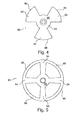
- Figure 4 is a plan view of a third embodiment of the rotor of Figure 1 ;
- Figure 5 is a plan view of a fourth embodiment of the rotor of Figure 1 ;
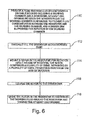
- Figure 6 is a flow chart illustrating a method according to an embodiment of the present invention.
- FIG. 1 illustrates a fluid friction clutch 10 according to an embodiment of the present invention.
- the clutch 10 includes a housing 12 that includes a working chamber 14 and a reservoir 16 separated by a wall 18 having at least one opening 20 for providing fluid communicating between the reservoir 16 and the working chamber 14.
- the housing 12 is mounted on a drive shaft 22 via bearings 24, and a driven disk 26 in working chamber 14 is connected to the drive shaft 22 and rotates when drive shaft 22 rotates.
- a cooling fan (not illustrated) may be mounted on housing 12, and the clutch 10 determines the speed of the housing 12 relative to the drive shaft 22 and thus the speed of the cooling fan.
- a rotor shaft 28 extends through the wall 18 and supports a rotor 30 in reservoir 16 for rotation with the drive shaft 22 and the driven disk 26.
- a solenoid 32 controls the position of a valve lever 34 relative to opening 20 and selectively moves the valve lever 34 between open and closed positions relative to
- the amount of working fluid in working chamber 14 affects the degree of coupling between the driven disk 26 and the housing 12.
- the drive shaft is only coupled to the housing via bearings 24 and an air interface between driven disk 26 and the walls of the working housing.
- Rotor 30 is spaced sufficiently far from wall 18 such that there is little if any coupling between the rotor 30 and the wall 18 via the working fluid in the reservoir.
- Housing 12 rotates slowly when the working chamber 14 is empty When working fluid is released into working chamber 14 by valve lever 34 uncovering opening 20, the fluid couples the driven disk 26 to the housing 12, and the rotation of the housing 12 increases. The increased rotation of housing 12 helps to distribute the working fluid in the reservoir 16 in a ring and maintain a flow of fluid toward opening 20.
- the working fluid returns to the reservoir 16 via return passages, and additional working fluid must be released from reservoir 16 to maintain the coupling between the driven disk 26 and the housing.
- the working fluid circulates between the working chamber 14 and the reservoir 16 in this manner until valve lever 34 is closed.
- the low degree of coupling between the driven disk 26 and the housing 12 does not distribute the working fluid evenly throughout the reservoir, and the movement of working fluid from reservoir 16 to working chamber 14 may be slower than optimal when valve lever 34 is moved to uncover opening 20.
- the distribution of the working fluid in the reservoir 16 is improved by rotor 30 which creates a circular flow of air in the reservoir as it spins, and this rotation of the rotor entrains the working fluid and distributes it in a ring in the reservoir 16, thus placing some of the fluid near opening 20 to provide enhanced flow of the fluid into the working chamber when the valve 34 opens.
- the rotor 30 is spaced from wall 18 of reservoir 16 sufficiently so that the rotation of the rotor 30 is not (or is only slightly) coupled to the housing 12. Thus the spinning of the rotor 30 in the reservoir 16 does not significantly shear the working fluid and does not contribute to the degradation of the working fluid.
- Rotor 30 is illustrated in Figure 2 and is formed from a disk 36 having an outer periphery 48 and generally parallel sides 40. Substantially linear slots 42 are cut or formed in disk 36 and extend along non-radial chords of disk 36 to periphery 48 and define a plurality of arms 50 spaced apart by slots 42. Rotor 30 is intended to be mounted so that it will rotate in the direction of arrow 52, clockwise in Figure 2 , with the acutely angled ends 54 of arms 50 moving in the direction of arrow 52. While four slots 42 defining four arms 50 are illustrated in Figure 2 , rotor 30 could include greater or smaller number of slots 42.
- slots help promote a circular flow of air in reservoir 16 as rotor 30 rotates, and the rotation of rotor 30 entrains the working fluid and draws it into a ring in the interior of the reservoir 16.
- the length of slots 42 is selected to be long enough to allow for the passage of air from one side of the disk to the other even when the rotor 30 is wetted during operation and creates a partial hydraulic seal between rotor 30 and wall 18. Distributing the working fluid in a ring in this manner allows for the fluid to enter working chamber 14 in a timely manner when valve lever 34 uncovers opening 20.
- Rotor 60 comprises a disk 62 having an outer periphery 64 and generally parallel sides 66.
- Arcuate slots 68 are cut or formed in disk 62 which slots 68 extend to periphery 64 of disk 62 and define a plurality of arms 70.
- Rotor 60 is intended to be mounted for rotation in the direction of arrow 72, clockwise in Figure 3 , so that the acutely angled ends 74 of arms 70 move forward in the rotation direction 72.
- the arcuate arms will establish a circular flow of fluid in reservoir 16 when the rotor 60 rotates which will entrain the working fluid and form a ring of fluid inside the reservoir 16.
- the lengths of slots 68 are selected to be long enough to allow for the passage of air from one side of the disk 62 to the other even when the rotor 60 rotates and forms a partial hydraulic seal with wall 18.
- Rotor 80 comprises a central body portion 82 from which a plurality of arms 84 project.
- the outer edges 86 of arms 84 are arcuate and lie along arcs of a single circle, and the circumferential width of the arms increases in a direction away from the rotor's axis of rotation.
- the sides 88 of rotor 80, including arms 84 are generally planar. The rotation of rotor 80, as in the previous embodiments, generates a circular flow of fluid in the reservoir 16, and forms a ring of working fluid inside reservoir 16.
- Rotor 90 includes a central body portion 92 from which a plurality of arms 94 extend. The arms 94 are connected by arcuate segments 96 which together form an outer peripheral ring of rotor 90.
- the rotation of rotor 90 like the previous embodiments, generates a circular flow of fluid inside reservoir 16 as it entrains the working fluid in the reservoir 16 and forms a ring of working fluid inside reservoir 16.
- the method includes a block 110 of providing a fluid friction clutch comprising a drivable housing including a working chamber and a reservoir, at least one opening between the reservoir and the working chamber configured to provide fluid communication between the reservoir and the working chamber, and a driven disk supported for rotation in the working chamber.
- the method involves effecting fluid transfer from the reservoir to the working chamber and includes a block 112 of partially filling the reservoir with a working fluid, a block 114 of mounting a rotor in the reservoir for rotation about an axis of rotation, the rotor comprising a plurality of arms, separated by a plurality of gaps, projecting away from the axis of rotation, and a block 116 of coupling the rotor to the driven disk.
- the method also includes a block 118 of driving the rotor in the reservoir to distribute the working fluid around the reservoir and toward the at least one opening.
Landscapes
- Engineering & Computer Science (AREA)
- General Engineering & Computer Science (AREA)
- Physics & Mathematics (AREA)
- Electromagnetism (AREA)
- Mechanical Engineering (AREA)
- Hydraulic Clutches, Magnetic Clutches, Fluid Clutches, And Fluid Joints (AREA)
- Braking Arrangements (AREA)
Applications Claiming Priority (1)
| Application Number | Priority Date | Filing Date | Title |
|---|---|---|---|
| US12/566,363 US9435386B2 (en) | 2009-09-24 | 2009-09-24 | Fluid friction clutch |
Publications (2)
| Publication Number | Publication Date |
|---|---|
| EP2302247A2 true EP2302247A2 (de) | 2011-03-30 |
| EP2302247A3 EP2302247A3 (de) | 2011-11-30 |
Family
ID=43334386
Family Applications (1)
| Application Number | Title | Priority Date | Filing Date |
|---|---|---|---|
| EP10179468A Withdrawn EP2302247A3 (de) | 2009-09-24 | 2010-09-24 | Flüssigkeitsrutschkupplung |
Country Status (2)
| Country | Link |
|---|---|
| US (1) | US9435386B2 (de) |
| EP (1) | EP2302247A3 (de) |
Cited By (1)
| Publication number | Priority date | Publication date | Assignee | Title |
|---|---|---|---|---|
| CN105299084A (zh) * | 2014-07-07 | 2016-02-03 | 舍弗勒技术股份两合公司 | 用于摩擦离合器的具有旋转轴线的万向环单元 |
Families Citing this family (4)
| Publication number | Priority date | Publication date | Assignee | Title |
|---|---|---|---|---|
| US8657090B2 (en) * | 2010-07-22 | 2014-02-25 | Tai-Her Yang | Clutch actuated by initial limit-torque sliding damping |
| AU2014240621B2 (en) | 2013-03-14 | 2017-06-29 | Horton, Inc. | Viscous clutch and associated reservoir configuration |
| CN104454116A (zh) * | 2013-09-24 | 2015-03-25 | 北汽福田汽车股份有限公司 | 用于发动机的风扇离合装置以及具有其的发动机 |
| CN118881664B (zh) * | 2024-09-30 | 2024-12-31 | 温州奕龙汽车零部件有限公司 | 一种机械回油式硅油离合器 |
Family Cites Families (12)
| Publication number | Priority date | Publication date | Assignee | Title |
|---|---|---|---|---|
| GB849933A (en) | 1957-05-31 | 1960-09-28 | Schwitzer Corp | Fluid coupling mechanism |
| GB1580453A (en) | 1976-05-11 | 1980-12-03 | Holset Engineering Co | Fluid couplings |
| DE3029992C2 (de) | 1980-08-08 | 1982-05-27 | Süddeutsche Kühlerfabrik Julius Fr. Behr GmbH & Co KG, 7000 Stuttgart | Flüssigkeitsreibungskupplung |
| DE3702299C1 (de) * | 1987-01-27 | 1988-03-10 | Viscodrive Gmbh | Fluessigkeitsreibungskupplung |
| AT388977B (de) * | 1988-04-27 | 1989-09-25 | Steyr Daimler Puch Ag | Lamelle fuer fluessigkeitsreibungskupplungen |
| US5484045A (en) | 1994-03-16 | 1996-01-16 | Usui Kokusai Sangyo Kaisha Ltd. | Fluid clutch |
| JP3346644B2 (ja) * | 1994-03-19 | 2002-11-18 | 臼井国際産業株式会社 | 液体クラッチ |
| DE19533641B4 (de) * | 1995-09-12 | 2005-11-10 | Behr Gmbh & Co. Kg | Flüssigkeitsreibungskupplung |
| DE19742823B4 (de) * | 1997-09-27 | 2004-05-19 | Behr Gmbh & Co. | Flüssigkeitsreibungskupplung |
| US6026943A (en) * | 1999-04-16 | 2000-02-22 | Eaton Corporation | Segmented reservoir for viscous clutches |
| US6752251B2 (en) * | 2002-11-04 | 2004-06-22 | Borgwarner, Inc. | Electronically controlled viscous fan drive |
| JP4813868B2 (ja) * | 2004-11-09 | 2011-11-09 | 臼井国際産業株式会社 | 外部制御式ファン・カップリング装置 |
-
2009
- 2009-09-24 US US12/566,363 patent/US9435386B2/en not_active Expired - Fee Related
-
2010
- 2010-09-24 EP EP10179468A patent/EP2302247A3/de not_active Withdrawn
Cited By (2)
| Publication number | Priority date | Publication date | Assignee | Title |
|---|---|---|---|---|
| CN105299084A (zh) * | 2014-07-07 | 2016-02-03 | 舍弗勒技术股份两合公司 | 用于摩擦离合器的具有旋转轴线的万向环单元 |
| CN105299084B (zh) * | 2014-07-07 | 2019-12-06 | 舍弗勒技术股份两合公司 | 用于摩擦离合器的具有旋转轴线的万向环单元 |
Also Published As
| Publication number | Publication date |
|---|---|
| EP2302247A3 (de) | 2011-11-30 |
| US20110067970A1 (en) | 2011-03-24 |
| US9435386B2 (en) | 2016-09-06 |
Similar Documents
| Publication | Publication Date | Title |
|---|---|---|
| US9435386B2 (en) | Fluid friction clutch | |
| US4987986A (en) | Electromagnetically actuated valve plate for a viscous fluid fan clutch | |
| EP2501951B1 (de) | Integrierte viskosekupplung | |
| US8875861B2 (en) | Liquid friction clutch | |
| JPS61109922A (ja) | 流体摩擦クラツチ | |
| WO2018061443A1 (ja) | 車両用駆動装置 | |
| JPH11101272A (ja) | 流体摩擦クラッチ | |
| US6247567B1 (en) | Fluid clutch | |
| US20020088411A1 (en) | Electronically controlled magnetorheological fluid based cooling fan drive assembly | |
| JPH0255648B2 (de) | ||
| GB2028470A (en) | Shear type fluid coupling | |
| KR101602586B1 (ko) | 클러치 유닛 | |
| JP2021505821A (ja) | 内部潤滑システムを有するドライブラインユニット | |
| US4940121A (en) | Fluid friction clutch | |
| US4238015A (en) | Temperature responsive viscous fan drive | |
| US2341985A (en) | Pump | |
| US20140360835A1 (en) | Fluid friction clutch | |
| US20020185354A1 (en) | Viscous fluid coupling with dragging rotation reduction arrangement | |
| EP0656990B1 (de) | Vorrichtung zum antrieb eines nebenaggregats eines kraftfahrzeugs, insbesondere eines kühlerlüfters einer brennkraftmaschine | |
| US4974713A (en) | Fluid friction clutch | |
| JP7735317B2 (ja) | 粘性摩擦クラッチの弁制御システム | |
| GB2043843A (en) | Hydrodynamic torque converter | |
| WO2016134201A1 (en) | Fluid friction clutch | |
| CN1989368A (zh) | 供油装置 | |
| KR100419724B1 (ko) | 차량자동변속기의윤활장치 |
Legal Events
| Date | Code | Title | Description |
|---|---|---|---|
| PUAI | Public reference made under article 153(3) epc to a published international application that has entered the european phase |
Free format text: ORIGINAL CODE: 0009012 |
|
| AK | Designated contracting states |
Kind code of ref document: A2 Designated state(s): AL AT BE BG CH CY CZ DE DK EE ES FI FR GB GR HR HU IE IS IT LI LT LU LV MC MK MT NL NO PL PT RO SE SI SK SM TR |
|
| AX | Request for extension of the european patent |
Extension state: BA ME RS |
|
| RIN1 | Information on inventor provided before grant (corrected) |
Inventor name: MCDERMOTT, DAVID Inventor name: HARTER, MICHAEL |
|
| RIN1 | Information on inventor provided before grant (corrected) |
Inventor name: MCDERMOTT, DAVID Inventor name: HARTER, MICHAEL |
|
| PUAL | Search report despatched |
Free format text: ORIGINAL CODE: 0009013 |
|
| AK | Designated contracting states |
Kind code of ref document: A3 Designated state(s): AL AT BE BG CH CY CZ DE DK EE ES FI FR GB GR HR HU IE IS IT LI LT LU LV MC MK MT NL NO PL PT RO SE SI SK SM TR |
|
| AX | Request for extension of the european patent |
Extension state: BA ME RS |
|
| RIC1 | Information provided on ipc code assigned before grant |
Ipc: F16D 35/02 20060101AFI20111026BHEP |
|
| 17P | Request for examination filed |
Effective date: 20120530 |
|
| 17Q | First examination report despatched |
Effective date: 20121005 |
|
| STAA | Information on the status of an ep patent application or granted ep patent |
Free format text: STATUS: THE APPLICATION IS DEEMED TO BE WITHDRAWN |
|
| 18D | Application deemed to be withdrawn |
Effective date: 20140408 |