EP2302255A2 - Dispositif d'entraînement pour au moins un engrenage auxiliaire - Google Patents
Dispositif d'entraînement pour au moins un engrenage auxiliaire Download PDFInfo
- Publication number
- EP2302255A2 EP2302255A2 EP10007259A EP10007259A EP2302255A2 EP 2302255 A2 EP2302255 A2 EP 2302255A2 EP 10007259 A EP10007259 A EP 10007259A EP 10007259 A EP10007259 A EP 10007259A EP 2302255 A2 EP2302255 A2 EP 2302255A2
- Authority
- EP
- European Patent Office
- Prior art keywords
- drive
- drive device
- vibration damper
- torsional vibration
- output shaft
- Prior art date
- Legal status (The legal status is an assumption and is not a legal conclusion. Google has not performed a legal analysis and makes no representation as to the accuracy of the status listed.)
- Granted
Links
Images


Classifications
-
- F—MECHANICAL ENGINEERING; LIGHTING; HEATING; WEAPONS; BLASTING
- F16—ENGINEERING ELEMENTS AND UNITS; GENERAL MEASURES FOR PRODUCING AND MAINTAINING EFFECTIVE FUNCTIONING OF MACHINES OR INSTALLATIONS; THERMAL INSULATION IN GENERAL
- F16F—SPRINGS; SHOCK-ABSORBERS; MEANS FOR DAMPING VIBRATION
- F16F15/00—Suppression of vibrations in systems; Means or arrangements for avoiding or reducing out-of-balance forces, e.g. due to motion
- F16F15/10—Suppression of vibrations in rotating systems by making use of members moving with the system
- F16F15/12—Suppression of vibrations in rotating systems by making use of members moving with the system using elastic members or friction-damping members, e.g. between a rotating shaft and a gyratory mass mounted thereon
- F16F15/131—Suppression of vibrations in rotating systems by making use of members moving with the system using elastic members or friction-damping members, e.g. between a rotating shaft and a gyratory mass mounted thereon the rotating system comprising two or more gyratory masses
- F16F15/133—Suppression of vibrations in rotating systems by making use of members moving with the system using elastic members or friction-damping members, e.g. between a rotating shaft and a gyratory mass mounted thereon the rotating system comprising two or more gyratory masses using springs as elastic members, e.g. metallic springs
- F16F15/1336—Leaf springs, e.g. radially extending
-
- F—MECHANICAL ENGINEERING; LIGHTING; HEATING; WEAPONS; BLASTING
- F02—COMBUSTION ENGINES; HOT-GAS OR COMBUSTION-PRODUCT ENGINE PLANTS
- F02B—INTERNAL-COMBUSTION PISTON ENGINES; COMBUSTION ENGINES IN GENERAL
- F02B67/00—Engines characterised by the arrangement of auxiliary apparatus not being otherwise provided for, e.g. the apparatus having different functions; Driving auxiliary apparatus from engines, not otherwise provided for
- F02B67/04—Engines characterised by the arrangement of auxiliary apparatus not being otherwise provided for, e.g. the apparatus having different functions; Driving auxiliary apparatus from engines, not otherwise provided for of mechanically-driven auxiliary apparatus
-
- F—MECHANICAL ENGINEERING; LIGHTING; HEATING; WEAPONS; BLASTING
- F16—ENGINEERING ELEMENTS AND UNITS; GENERAL MEASURES FOR PRODUCING AND MAINTAINING EFFECTIVE FUNCTIONING OF MACHINES OR INSTALLATIONS; THERMAL INSULATION IN GENERAL
- F16F—SPRINGS; SHOCK-ABSORBERS; MEANS FOR DAMPING VIBRATION
- F16F15/00—Suppression of vibrations in systems; Means or arrangements for avoiding or reducing out-of-balance forces, e.g. due to motion
- F16F15/10—Suppression of vibrations in rotating systems by making use of members moving with the system
- F16F15/12—Suppression of vibrations in rotating systems by making use of members moving with the system using elastic members or friction-damping members, e.g. between a rotating shaft and a gyratory mass mounted thereon
- F16F15/121—Suppression of vibrations in rotating systems by making use of members moving with the system using elastic members or friction-damping members, e.g. between a rotating shaft and a gyratory mass mounted thereon using springs as elastic members, e.g. metallic springs
- F16F15/1215—Leaf springs, e.g. radially extending
-
- F—MECHANICAL ENGINEERING; LIGHTING; HEATING; WEAPONS; BLASTING
- F16—ENGINEERING ELEMENTS AND UNITS; GENERAL MEASURES FOR PRODUCING AND MAINTAINING EFFECTIVE FUNCTIONING OF MACHINES OR INSTALLATIONS; THERMAL INSULATION IN GENERAL
- F16F—SPRINGS; SHOCK-ABSORBERS; MEANS FOR DAMPING VIBRATION
- F16F15/00—Suppression of vibrations in systems; Means or arrangements for avoiding or reducing out-of-balance forces, e.g. due to motion
- F16F15/10—Suppression of vibrations in rotating systems by making use of members moving with the system
- F16F15/16—Suppression of vibrations in rotating systems by making use of members moving with the system using a fluid or pasty material
Definitions
- the invention relates to a drive device for at least one secondary drive on a power output shaft of an internal combustion engine, in particular on a crankshaft, according to the preamble of claim 1.
- a torsional vibration damper with an absorber mass or a secondary part to reduce the torsional moments due to vibration.
- the secondary drive driven directly by the crankshaft may possibly have an additional torsional vibration damper.
- Such a drive device describes, for example, the DE 41 03 213 A1 with a belt drive as secondary drive.
- Such auxiliary drives by means of a spur gear with at least one directly on a journal of the crankshaft spur gear used for example to drive a water pump, a compressor, etc. and possibly require as described above an additional torsional vibration damper to create a smooth, satisfactorily low-wear secondary drive.
- the object of the invention is to propose a drive device for at least one secondary drive on a power output shaft of an internal combustion engine, which meets both criteria at a reduced construction cost, namely an adequate vibration damping of the power output shaft and at the same time providing a smooth, low-wear secondary drive.
- the at least one secondary drive-drive element is indirectly or directly coupled, in particular driven, to the secondary part of the torsional vibration damper.
- the secondary part is subject to lower angular acceleration than the power output shaft, in particular the crankshaft, the internal combustion engine, so that with a corresponding drive coupling of the secondary engine this requires no further torsional vibration damper and still works smoothly and wear.
- the "detuning" of the vibration damper resulting from the coupling of the at least one secondary drive can be adjusted by empirical tests and / or by calculations such that both criteria are satisfied satisfactorily; a possibly slightly increasing torsional load in the power output shaft is negligible.
- the at least one secondary drive drive element and / or the secondary part of the torsional vibration damper is rotatably mounted on the power output shaft, for example on a journal of the power output shaft.
- the primary part and the secondary part with the interposition of vibration damping means can be arranged radially one above the other, wherein the at least one drive element is driven via the outer ring as a secondary part.
- the at least one spur gear can be indirectly coupled to the secondary part via a preferably flexible and / or torsionally stiff force transmission and / or coupling element, in particular via a disc-shaped, radially and / or axially resilient, thin-walled driving plate. This allows a rigid in the direction of rotation drive connection, but limited to achieve a stress-free coupling of the spur gear in the axial and radial directions is limited and compensates, for example, even minor misalignment.
- the driver plate for example, can in a structurally particularly simple manner have a plurality of webs provided between a central disk ring and, if appropriate, a radially outer disk ring, which are made correspondingly yielding by their shaping (wavy) and geometry (web width, plate thickness).
- the at least one spur gear to achieve a compact, flat in the radial direction or crowded by means of at least one needle bearing on the pin of the power output shaft to be rotatably mounted.
- at least one needle bearing on the pin of the power output shaft to be rotatably mounted.
- a simple plain bearing since, for example, no speed differences occur between the bearing pin of the power output shaft and the spur gear.
- a plurality of, preferably non-rotatably coupled or connected, drive elements and / or the secondary part of the torsional vibration damper can be rotatably mounted on the power output shaft, preferably on the journal of the power output shaft.
- the secondary part on the journal The power take-off shaft can usually account for the above-mentioned driving plate.
- the bearings of the spur gears and possibly the secondary part are then preferably formed by one or more needle roller bearings or plain bearings, which form a smooth, compact storage of the immediately adjacent functional parts.
- the torsional vibration damper can be arranged at the front end of the power output shaft and / or can be positioned at least one drive element of the secondary drive between the torsional vibration damper and the housing of the internal combustion engine and thus be coupled in quasi-return to the secondary part.
- the drive element formed for example by at least one spur gear be arranged in the immediate vicinity of the housing-side mounting of the power output shaft and transmit high torques.
- the torsional vibration damper may be particularly preferably hydraulically damped to ensure a particularly quiet, low-vibration transmission of torque from the torsional vibration damper to the secondary drive.
- a preferred embodiment of the invention can be provided for this purpose between an inner ring as the primary part and a radially outer ring as a secondary part of the torsional vibration damper, a plurality of star-shaped, flexurally elastic fins, which protrude resiliently in corresponding radial slots in the circumferential direction, wherein the radial slots are filled with a damping fluid ,
- the damping fluid may be directly lubricating oil of the internal combustion engine, in particular if the torsional vibration damper is positioned with the secondary engine in a common, closed engine compartment.
- the radial slots in the outer ring of the torsional vibration damper can be formed by mutually circumferentially spaced, circular segment-shaped intermediate pieces, which are clamped between two flange rings and an outer support ring to achieve a manufacturing technology favorable design.
- the intermediate pieces are preferably fastened by means of the flange rings and the intermediate pieces penetrating screws.
- manufacturing and assembly technology can be advantageously incorporated on the inner ring axially parallel grooves, in each of which protrude the bending elastic slats. Further, it is preferably provided that the flange rings of the secondary part annularly surround the inner ring of the primary part at its end faces. This also makes a manufacturing and assembly technology is easier, more compact and cheaper construction achieved.
- the at least one secondary drive drive element is preferably formed by a drive wheel of a toothed drive, preferably by a spur gear, which enables a functionally reliable power transmission to the secondary drive, for example to a drive wheel of a water pump, etc.
- the Fig. 1 and 2 show a first drive device 1 on a crankshaft 2 as a power output shaft of an internal combustion engine, at whose end-side end a hydraulically damped torsional vibration damper 3 is attached.
- crankshaft 2 is in a known manner via main journals 2a (it is only a main journal 2a visible) in a in Fig. 2 only indicated machine housing 4 rotatably mounted.
- a further bearing pin 5 connects with a smaller diameter guide pin 6 at.
- a spur gear 8 is rotatably supported via a needle bearing 7, which serves as a drive gear for a secondary drive of the internal combustion engine, not shown, for example, to drive a built-in machine housing water pump, a compressor, etc ..
- the torsional vibration damper 3 is composed essentially of an inner ring 9 as a primary part and an outer ring 10 as a secondary part or secondary mass, which are connected to each other via vibration damping means.
- the inner ring 9 is screwed by means of several screws 11 with the bearing pin 5 of the crankshaft 2, wherein the inner peripheral surface is centered on the guide pin 6 as can be seen.
- the outer ring 10 is provided with an annular flange 10a facing the crankshaft 2, which is fixedly connected to the spur gear 8 of the secondary drive via a torsion-resistant driving plate 12 in the circumferential direction.
- the driver plate 12 made of a thin-walled sheet steel has a radially inner disc ring 12a and an outer disc ring 12b, which are interconnected via a plurality of circumferentially distributed webs 12c.
- the disc rings 12a, 12b are screwed by means of several screws 13 with the spur gear 8 and the flange 10a firmly.
- the webs 12 c are by their geometry or by corrugated areas and by, for example, different, decreasing from the inside to the outside web widths (see Fig. 1 and 2 ) are designed so that they slight misalignment of the outer ring 10 with respect to the on the journal Balancing 5 rotatably mounted spur gear 8 and thus eliminate any possible tension.
- the Fig. 3 shows a further drive device 14, which is described only insofar as they differ from the embodiment according to the Fig. 1 and 2 different. Functionally identical parts are provided with the same reference numerals.
- the separately manufactured spur gears 8, 15 are bolted by means of several, continuous screws 17 with the flange 10a of the torsional vibration damper 3.
- a hub portion 10b is integrally formed on the flange 10a, which is rotatably mounted on the bearing journal 5 of the crankshaft 2 via further plain bearing shells 16.
- annular shoulders 8a, 8b are incorporated in the middle spur gear 8, in which the flange 10b and a smaller diameter, annular guide portion 15a of the spur gear 15 protrude.
- a common plain bearing 16 or as stated above one or more needle roller bearings 7 may be used.
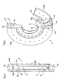
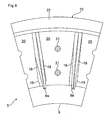
- the 4 to 6 show the construction of the hydraulic damping damper 3 according to FIGS Fig. 1 and 2 in detail.
- the inner ring 9 as a primary part on its outer circumference on a plurality of axially parallel grooves 9a, in each of which arranged in pairs, star-shaped, bending elastic fins 18 protrude.
- the slats 18 are inserted into radial slots 19 of the outer ring 10, which radial slots 19 are each formed between circular segment-shaped intermediate pieces 20 of the outer ring 10.
- the fins 18 have a greater thickness in their radially outer region and are firmly clamped in the intermediate pieces 20.
- the radially inner region of the lamellae 18 has a circumferential clearance in both directions of rotation with respect to the radial slots 19, via which the outer ring 10 can absorb torsional vibrations within the circumferential clearance relative to the inner ring 9 starting from a central basic position of the lamellae.
- the intermediate pieces 20 are firmly screwed together with the mutual flange rings 10a and 10d of the outer ring 10 by means of a plurality of screws 21, wherein they comprise the inner ring 9 and an outer support ring 22 with their radially inner and radially outer edge regions.
- the radial slots are filled with a hydraulically damping fluid which, when oscillation amplitudes occur, occurs between those formed around the disks 18 Chambers or slots is displaced back and forth accordingly.
- the radial slots 19 are sealed relative to the inner ring 9 and the flange rings 10a, 10d by means of sealing rings 23 on both sides.
- the damping fluid may be lubricating oil from the lubricating oil system of the internal combustion engine.
- the torsional vibration damper 3 according to the 4 to 6 can in adaptation to the embodiment according to Fig. 3 be executed at its flange 10a as described with a hub portion 10b.
- the described drive device 1 or 14 can also be provided at another power output shaft of the internal combustion engine, for example at an intermediate shaft or at a camshaft with coupled secondary drive.
Landscapes
- Engineering & Computer Science (AREA)
- General Engineering & Computer Science (AREA)
- Mechanical Engineering (AREA)
- Physics & Mathematics (AREA)
- Acoustics & Sound (AREA)
- Aviation & Aerospace Engineering (AREA)
- Chemical & Material Sciences (AREA)
- Combustion & Propulsion (AREA)
- Gears, Cams (AREA)
- Gear Transmission (AREA)
Applications Claiming Priority (1)
| Application Number | Priority Date | Filing Date | Title |
|---|---|---|---|
| DE102009042682A DE102009042682A1 (de) | 2009-09-23 | 2009-09-23 | Antriebsvorrichtung für zumindest einen Nebentrieb |
Publications (3)
| Publication Number | Publication Date |
|---|---|
| EP2302255A2 true EP2302255A2 (fr) | 2011-03-30 |
| EP2302255A3 EP2302255A3 (fr) | 2017-12-20 |
| EP2302255B1 EP2302255B1 (fr) | 2020-03-25 |
Family
ID=43365857
Family Applications (1)
| Application Number | Title | Priority Date | Filing Date |
|---|---|---|---|
| EP10007259.4A Active EP2302255B1 (fr) | 2009-09-23 | 2010-07-14 | Dispositif d'entraînement pour au moins un engrenage auxiliaire |
Country Status (3)
| Country | Link |
|---|---|
| EP (1) | EP2302255B1 (fr) |
| CN (1) | CN102022186B (fr) |
| DE (1) | DE102009042682A1 (fr) |
Families Citing this family (3)
| Publication number | Priority date | Publication date | Assignee | Title |
|---|---|---|---|---|
| EP3604854B1 (fr) * | 2017-03-31 | 2024-01-10 | TMT Machinery, Inc. | Dispositif d'amortissement de vibrations et système de support de bobine |
| DE102021112074A1 (de) * | 2021-05-10 | 2022-11-10 | Schaeffler Technologies AG & Co. KG | Drehschwingungsdämpfer und Verfahren zur Zentrierung und Befestigung eines Drehschwingungsdämpfers |
| CN118622893B (zh) * | 2024-07-01 | 2025-12-12 | 西安交通大学 | 用于缓冲吸能的负泊松比管状结构及制造方法 |
Citations (1)
| Publication number | Priority date | Publication date | Assignee | Title |
|---|---|---|---|---|
| DE4103213A1 (de) | 1990-02-06 | 1991-08-08 | Luk Lamellen & Kupplungsbau | Riemenscheibe |
Family Cites Families (13)
| Publication number | Priority date | Publication date | Assignee | Title |
|---|---|---|---|---|
| JPS6079124A (ja) * | 1983-10-05 | 1985-05-04 | Isuzu Motors Ltd | エンジンの騒音低減装置 |
| DE4117580C2 (de) * | 1990-05-31 | 2002-02-28 | Luk Lamellen & Kupplungsbau | Drehmomentübertragungseinrichtung |
| DE4117584B4 (de) * | 1990-05-31 | 2006-09-07 | Luk Lamellen Und Kupplungsbau Beteiligungs Kg | Geteiltes Schwungrad |
| DE4225304B4 (de) * | 1991-08-07 | 2009-01-08 | Luk Lamellen Und Kupplungsbau Beteiligungs Kg | Scheibenförmiges Bauteil |
| AT398462B (de) * | 1993-07-15 | 1994-12-27 | Geislinger Co Schwingungstechn | Drehschwingungsdämpfer bzw. drehelastische kupplung |
| AT406293B (de) * | 1998-05-08 | 2000-03-27 | Ellergon Antriebstech Gmbh | Drehschwingungsdämpfer bzw. drehelastische und schwingungsdämpfende kupplung |
| FR2838490B1 (fr) * | 2002-04-10 | 2004-05-28 | Valeo | Double volant amortisseur, en particulier pour vehicule automobile |
| DE102004008154B4 (de) * | 2004-02-19 | 2010-07-01 | Audi Ag | Antriebsanordnung für Nebentriebe von Brennkraftmaschinen |
| ATE541116T1 (de) * | 2004-07-02 | 2012-01-15 | Schaeffler Technologies Gmbh | Triebrad zum antreiben eines nebenaggregates eines fahrzeuges |
| US7966817B2 (en) * | 2005-03-26 | 2011-06-28 | Luk Vermoegensverwaltungsgesellschaft Mbh | Compound transmission |
| WO2007051627A1 (fr) * | 2005-11-04 | 2007-05-10 | Borgwarner Inc. | Amortisseur de vibrations de torsion avec un accouplement a un vilebrequin et combinaison d'un amortisseur de vibrations de torsion et d'un accouplement |
| US7758465B2 (en) * | 2007-06-04 | 2010-07-20 | The Gates Corporation | Damped planetary transmission |
| CN201250877Y (zh) * | 2008-07-07 | 2009-06-03 | 奇瑞汽车股份有限公司 | 一种新型汽车发动机曲轴扭转减振器 |
-
2009
- 2009-09-23 DE DE102009042682A patent/DE102009042682A1/de not_active Withdrawn
-
2010
- 2010-07-14 EP EP10007259.4A patent/EP2302255B1/fr active Active
- 2010-09-21 CN CN201010293080.6A patent/CN102022186B/zh not_active Expired - Fee Related
Patent Citations (1)
| Publication number | Priority date | Publication date | Assignee | Title |
|---|---|---|---|---|
| DE4103213A1 (de) | 1990-02-06 | 1991-08-08 | Luk Lamellen & Kupplungsbau | Riemenscheibe |
Also Published As
| Publication number | Publication date |
|---|---|
| EP2302255B1 (fr) | 2020-03-25 |
| DE102009042682A1 (de) | 2011-03-24 |
| EP2302255A3 (fr) | 2017-12-20 |
| CN102022186A (zh) | 2011-04-20 |
| CN102022186B (zh) | 2015-05-20 |
Similar Documents
| Publication | Publication Date | Title |
|---|---|---|
| DE10059101B4 (de) | Antriebssystem | |
| DE102007017757B4 (de) | Oszillierendes innen eingreifendes Planetengetriebesystem | |
| EP1523610B1 (fr) | Dispositif permettant de modifier les temps de commande d'un moteur a combustion interne | |
| DE102004038681A1 (de) | Elektromotorischer Nockenwellenversteller | |
| DE4225304A1 (de) | Scheibenfoermiges bauteil | |
| WO2010043193A1 (fr) | Agencement d'arbre de commande pour une transmission d'un véhicule à moteur | |
| EP3415238B1 (fr) | Entraînement de broyeur vertical | |
| EP2299071B1 (fr) | Dispositif de modification d'une position d'angle de rotation relative d'un arbre à came par rapport à un vilebrequin d'un moteur à combustion interne | |
| DE102016116438B3 (de) | Abtriebselement für ein Spannungswellengetriebe | |
| DE10344485A1 (de) | Filter für eine Kraftübertragung mit automatisiertem Gangwechsel, in kontinuierlicher oder nicht kontinuierlicher Ausführung, insbesondere für Kraftfahrzeuge | |
| EP1943437A1 (fr) | Amortisseur de vibrations de torsion avec un accouplement a un vilebrequin et combinaison d'un amortisseur de vibrations de torsion et d'un accouplement | |
| DE102004008538B4 (de) | Differential mit einer Bolzenbefestigungsbaugruppe | |
| EP3483478B1 (fr) | Entraînement de roue | |
| EP3050194B1 (fr) | Module équipé d'une machine électrique | |
| EP0989076B1 (fr) | Transporteur à rouleau | |
| EP2302255B1 (fr) | Dispositif d'entraînement pour au moins un engrenage auxiliaire | |
| EP2530260B1 (fr) | Arbre d'embrayage, actionneur, boîte de vitesses à dispositif de réglage d'arbre à came et régulateur de l'arbre à came | |
| DE102004041751B4 (de) | Nockenwellenversteller mit einer Kupplung zwischen einer Stellwelle und einem Verstellgetriebe | |
| DE19933822A1 (de) | Leistungsverzweigungsgetriebe | |
| EP2569525B1 (fr) | Entraînement des auxiliaires | |
| DE10205767B4 (de) | Lamellen-Kupplungseinrichtung mit einer eingangseitigen Dämpfungs- oder/und Federelementanordnung | |
| DE102015116482B3 (de) | Zykloidgetriebe | |
| EP1756426B1 (fr) | Pompe | |
| EP1726847B1 (fr) | Combinaison d'un ammortisseur de torsion avec un embrayage | |
| WO2005103519A1 (fr) | Ensemble de transfert de force a bague d'arret ondulee |
Legal Events
| Date | Code | Title | Description |
|---|---|---|---|
| PUAI | Public reference made under article 153(3) epc to a published international application that has entered the european phase |
Free format text: ORIGINAL CODE: 0009012 |
|
| AK | Designated contracting states |
Kind code of ref document: A2 Designated state(s): AL AT BE BG CH CY CZ DE DK EE ES FI FR GB GR HR HU IE IS IT LI LT LU LV MC MK MT NL NO PL PT RO SE SI SK SM TR |
|
| AX | Request for extension of the european patent |
Extension state: BA ME RS |
|
| PUAL | Search report despatched |
Free format text: ORIGINAL CODE: 0009013 |
|
| AK | Designated contracting states |
Kind code of ref document: A3 Designated state(s): AL AT BE BG CH CY CZ DE DK EE ES FI FR GB GR HR HU IE IS IT LI LT LU LV MC MK MT NL NO PL PT RO SE SI SK SM TR |
|
| AX | Request for extension of the european patent |
Extension state: BA ME RS |
|
| RIC1 | Information provided on ipc code assigned before grant |
Ipc: F02B 67/04 20060101ALN20171110BHEP Ipc: F16F 15/16 20060101ALI20171110BHEP Ipc: F16F 15/121 20060101ALI20171110BHEP Ipc: F16F 15/133 20060101AFI20171110BHEP Ipc: F16H 55/14 20060101ALN20171110BHEP |
|
| STAA | Information on the status of an ep patent application or granted ep patent |
Free format text: STATUS: REQUEST FOR EXAMINATION WAS MADE |
|
| 17P | Request for examination filed |
Effective date: 20180618 |
|
| STAA | Information on the status of an ep patent application or granted ep patent |
Free format text: STATUS: EXAMINATION IS IN PROGRESS |
|
| 17Q | First examination report despatched |
Effective date: 20181116 |
|
| RAP1 | Party data changed (applicant data changed or rights of an application transferred) |
Owner name: MAN TRUCK & BUS SE |
|
| RIC1 | Information provided on ipc code assigned before grant |
Ipc: F16F 15/133 20060101AFI20190917BHEP Ipc: F02B 67/04 20060101ALN20190917BHEP Ipc: F16H 55/14 20060101ALN20190917BHEP Ipc: F16F 15/121 20060101ALI20190917BHEP Ipc: F16F 15/16 20060101ALI20190917BHEP |
|
| RIC1 | Information provided on ipc code assigned before grant |
Ipc: F02B 67/04 20060101ALN20190920BHEP Ipc: F16F 15/121 20060101ALI20190920BHEP Ipc: F16F 15/16 20060101ALI20190920BHEP Ipc: F16H 55/14 20060101ALN20190920BHEP Ipc: F16F 15/133 20060101AFI20190920BHEP |
|
| GRAP | Despatch of communication of intention to grant a patent |
Free format text: ORIGINAL CODE: EPIDOSNIGR1 |
|
| STAA | Information on the status of an ep patent application or granted ep patent |
Free format text: STATUS: GRANT OF PATENT IS INTENDED |
|
| RIC1 | Information provided on ipc code assigned before grant |
Ipc: F16F 15/133 20060101AFI20191022BHEP Ipc: F16H 55/14 20060101ALN20191022BHEP Ipc: F16F 15/121 20060101ALI20191022BHEP Ipc: F02B 67/04 20060101ALN20191022BHEP Ipc: F16F 15/16 20060101ALI20191022BHEP |
|
| INTG | Intention to grant announced |
Effective date: 20191106 |
|
| GRAS | Grant fee paid |
Free format text: ORIGINAL CODE: EPIDOSNIGR3 |
|
| GRAA | (expected) grant |
Free format text: ORIGINAL CODE: 0009210 |
|
| STAA | Information on the status of an ep patent application or granted ep patent |
Free format text: STATUS: THE PATENT HAS BEEN GRANTED |
|
| AK | Designated contracting states |
Kind code of ref document: B1 Designated state(s): AL AT BE BG CH CY CZ DE DK EE ES FI FR GB GR HR HU IE IS IT LI LT LU LV MC MK MT NL NO PL PT RO SE SI SK SM TR |
|
| REG | Reference to a national code |
Ref country code: GB Ref legal event code: FG4D Free format text: NOT ENGLISH |
|
| REG | Reference to a national code |
Ref country code: AT Ref legal event code: REF Ref document number: 1248913 Country of ref document: AT Kind code of ref document: T Effective date: 20200415 Ref country code: IE Ref legal event code: FG4D Free format text: LANGUAGE OF EP DOCUMENT: GERMAN |
|
| REG | Reference to a national code |
Ref country code: DE Ref legal event code: R096 Ref document number: 502010016545 Country of ref document: DE |
|
| REG | Reference to a national code |
Ref country code: NL Ref legal event code: FP |
|
| REG | Reference to a national code |
Ref country code: SE Ref legal event code: TRGR |
|
| PG25 | Lapsed in a contracting state [announced via postgrant information from national office to epo] |
Ref country code: FI Free format text: LAPSE BECAUSE OF FAILURE TO SUBMIT A TRANSLATION OF THE DESCRIPTION OR TO PAY THE FEE WITHIN THE PRESCRIBED TIME-LIMIT Effective date: 20200325 Ref country code: NO Free format text: LAPSE BECAUSE OF FAILURE TO SUBMIT A TRANSLATION OF THE DESCRIPTION OR TO PAY THE FEE WITHIN THE PRESCRIBED TIME-LIMIT Effective date: 20200625 |
|
| PG25 | Lapsed in a contracting state [announced via postgrant information from national office to epo] |
Ref country code: LV Free format text: LAPSE BECAUSE OF FAILURE TO SUBMIT A TRANSLATION OF THE DESCRIPTION OR TO PAY THE FEE WITHIN THE PRESCRIBED TIME-LIMIT Effective date: 20200325 Ref country code: HR Free format text: LAPSE BECAUSE OF FAILURE TO SUBMIT A TRANSLATION OF THE DESCRIPTION OR TO PAY THE FEE WITHIN THE PRESCRIBED TIME-LIMIT Effective date: 20200325 Ref country code: GR Free format text: LAPSE BECAUSE OF FAILURE TO SUBMIT A TRANSLATION OF THE DESCRIPTION OR TO PAY THE FEE WITHIN THE PRESCRIBED TIME-LIMIT Effective date: 20200626 Ref country code: BG Free format text: LAPSE BECAUSE OF FAILURE TO SUBMIT A TRANSLATION OF THE DESCRIPTION OR TO PAY THE FEE WITHIN THE PRESCRIBED TIME-LIMIT Effective date: 20200625 |
|
| REG | Reference to a national code |
Ref country code: LT Ref legal event code: MG4D |
|
| PG25 | Lapsed in a contracting state [announced via postgrant information from national office to epo] |
Ref country code: SM Free format text: LAPSE BECAUSE OF FAILURE TO SUBMIT A TRANSLATION OF THE DESCRIPTION OR TO PAY THE FEE WITHIN THE PRESCRIBED TIME-LIMIT Effective date: 20200325 Ref country code: EE Free format text: LAPSE BECAUSE OF FAILURE TO SUBMIT A TRANSLATION OF THE DESCRIPTION OR TO PAY THE FEE WITHIN THE PRESCRIBED TIME-LIMIT Effective date: 20200325 Ref country code: RO Free format text: LAPSE BECAUSE OF FAILURE TO SUBMIT A TRANSLATION OF THE DESCRIPTION OR TO PAY THE FEE WITHIN THE PRESCRIBED TIME-LIMIT Effective date: 20200325 Ref country code: PT Free format text: LAPSE BECAUSE OF FAILURE TO SUBMIT A TRANSLATION OF THE DESCRIPTION OR TO PAY THE FEE WITHIN THE PRESCRIBED TIME-LIMIT Effective date: 20200818 Ref country code: LT Free format text: LAPSE BECAUSE OF FAILURE TO SUBMIT A TRANSLATION OF THE DESCRIPTION OR TO PAY THE FEE WITHIN THE PRESCRIBED TIME-LIMIT Effective date: 20200325 Ref country code: CZ Free format text: LAPSE BECAUSE OF FAILURE TO SUBMIT A TRANSLATION OF THE DESCRIPTION OR TO PAY THE FEE WITHIN THE PRESCRIBED TIME-LIMIT Effective date: 20200325 Ref country code: IS Free format text: LAPSE BECAUSE OF FAILURE TO SUBMIT A TRANSLATION OF THE DESCRIPTION OR TO PAY THE FEE WITHIN THE PRESCRIBED TIME-LIMIT Effective date: 20200725 Ref country code: SK Free format text: LAPSE BECAUSE OF FAILURE TO SUBMIT A TRANSLATION OF THE DESCRIPTION OR TO PAY THE FEE WITHIN THE PRESCRIBED TIME-LIMIT Effective date: 20200325 |
|
| REG | Reference to a national code |
Ref country code: DE Ref legal event code: R097 Ref document number: 502010016545 Country of ref document: DE |
|
| PG25 | Lapsed in a contracting state [announced via postgrant information from national office to epo] |
Ref country code: ES Free format text: LAPSE BECAUSE OF FAILURE TO SUBMIT A TRANSLATION OF THE DESCRIPTION OR TO PAY THE FEE WITHIN THE PRESCRIBED TIME-LIMIT Effective date: 20200325 Ref country code: DK Free format text: LAPSE BECAUSE OF FAILURE TO SUBMIT A TRANSLATION OF THE DESCRIPTION OR TO PAY THE FEE WITHIN THE PRESCRIBED TIME-LIMIT Effective date: 20200325 |
|
| PLBE | No opposition filed within time limit |
Free format text: ORIGINAL CODE: 0009261 |
|
| STAA | Information on the status of an ep patent application or granted ep patent |
Free format text: STATUS: NO OPPOSITION FILED WITHIN TIME LIMIT |
|
| PG25 | Lapsed in a contracting state [announced via postgrant information from national office to epo] |
Ref country code: MC Free format text: LAPSE BECAUSE OF FAILURE TO SUBMIT A TRANSLATION OF THE DESCRIPTION OR TO PAY THE FEE WITHIN THE PRESCRIBED TIME-LIMIT Effective date: 20200325 Ref country code: PL Free format text: LAPSE BECAUSE OF FAILURE TO SUBMIT A TRANSLATION OF THE DESCRIPTION OR TO PAY THE FEE WITHIN THE PRESCRIBED TIME-LIMIT Effective date: 20200325 |
|
| REG | Reference to a national code |
Ref country code: CH Ref legal event code: PL |
|
| 26N | No opposition filed |
Effective date: 20210112 |
|
| GBPC | Gb: european patent ceased through non-payment of renewal fee |
Effective date: 20200714 |
|
| REG | Reference to a national code |
Ref country code: BE Ref legal event code: MM Effective date: 20200731 |
|
| PG25 | Lapsed in a contracting state [announced via postgrant information from national office to epo] |
Ref country code: GB Free format text: LAPSE BECAUSE OF NON-PAYMENT OF DUE FEES Effective date: 20200714 Ref country code: LU Free format text: LAPSE BECAUSE OF NON-PAYMENT OF DUE FEES Effective date: 20200714 Ref country code: CH Free format text: LAPSE BECAUSE OF NON-PAYMENT OF DUE FEES Effective date: 20200731 Ref country code: LI Free format text: LAPSE BECAUSE OF NON-PAYMENT OF DUE FEES Effective date: 20200731 |
|
| PG25 | Lapsed in a contracting state [announced via postgrant information from national office to epo] |
Ref country code: SI Free format text: LAPSE BECAUSE OF FAILURE TO SUBMIT A TRANSLATION OF THE DESCRIPTION OR TO PAY THE FEE WITHIN THE PRESCRIBED TIME-LIMIT Effective date: 20200325 Ref country code: BE Free format text: LAPSE BECAUSE OF NON-PAYMENT OF DUE FEES Effective date: 20200731 |
|
| PG25 | Lapsed in a contracting state [announced via postgrant information from national office to epo] |
Ref country code: IE Free format text: LAPSE BECAUSE OF NON-PAYMENT OF DUE FEES Effective date: 20200714 |
|
| REG | Reference to a national code |
Ref country code: AT Ref legal event code: MM01 Ref document number: 1248913 Country of ref document: AT Kind code of ref document: T Effective date: 20200714 |
|
| PG25 | Lapsed in a contracting state [announced via postgrant information from national office to epo] |
Ref country code: AT Free format text: LAPSE BECAUSE OF NON-PAYMENT OF DUE FEES Effective date: 20200714 |
|
| PG25 | Lapsed in a contracting state [announced via postgrant information from national office to epo] |
Ref country code: TR Free format text: LAPSE BECAUSE OF FAILURE TO SUBMIT A TRANSLATION OF THE DESCRIPTION OR TO PAY THE FEE WITHIN THE PRESCRIBED TIME-LIMIT Effective date: 20200325 Ref country code: MT Free format text: LAPSE BECAUSE OF FAILURE TO SUBMIT A TRANSLATION OF THE DESCRIPTION OR TO PAY THE FEE WITHIN THE PRESCRIBED TIME-LIMIT Effective date: 20200325 Ref country code: CY Free format text: LAPSE BECAUSE OF FAILURE TO SUBMIT A TRANSLATION OF THE DESCRIPTION OR TO PAY THE FEE WITHIN THE PRESCRIBED TIME-LIMIT Effective date: 20200325 |
|
| PG25 | Lapsed in a contracting state [announced via postgrant information from national office to epo] |
Ref country code: MK Free format text: LAPSE BECAUSE OF FAILURE TO SUBMIT A TRANSLATION OF THE DESCRIPTION OR TO PAY THE FEE WITHIN THE PRESCRIBED TIME-LIMIT Effective date: 20200325 Ref country code: AL Free format text: LAPSE BECAUSE OF FAILURE TO SUBMIT A TRANSLATION OF THE DESCRIPTION OR TO PAY THE FEE WITHIN THE PRESCRIBED TIME-LIMIT Effective date: 20200325 |
|
| PGFP | Annual fee paid to national office [announced via postgrant information from national office to epo] |
Ref country code: NL Payment date: 20250724 Year of fee payment: 16 |
|
| PGFP | Annual fee paid to national office [announced via postgrant information from national office to epo] |
Ref country code: DE Payment date: 20250728 Year of fee payment: 16 |
|
| PGFP | Annual fee paid to national office [announced via postgrant information from national office to epo] |
Ref country code: IT Payment date: 20250721 Year of fee payment: 16 |
|
| PGFP | Annual fee paid to national office [announced via postgrant information from national office to epo] |
Ref country code: FR Payment date: 20250725 Year of fee payment: 16 |
|
| PGFP | Annual fee paid to national office [announced via postgrant information from national office to epo] |
Ref country code: SE Payment date: 20250725 Year of fee payment: 16 |