EP2302256A2 - Unbalance correction device of propeller shaft - Google Patents
Unbalance correction device of propeller shaft Download PDFInfo
- Publication number
- EP2302256A2 EP2302256A2 EP10175630A EP10175630A EP2302256A2 EP 2302256 A2 EP2302256 A2 EP 2302256A2 EP 10175630 A EP10175630 A EP 10175630A EP 10175630 A EP10175630 A EP 10175630A EP 2302256 A2 EP2302256 A2 EP 2302256A2
- Authority
- EP
- European Patent Office
- Prior art keywords
- plate part
- weight plate
- propeller shaft
- shaft
- outer shaft
- Prior art date
- Legal status (The legal status is an assumption and is not a legal conclusion. Google has not performed a legal analysis and makes no representation as to the accuracy of the status listed.)
- Granted
Links
- 230000002093 peripheral effect Effects 0.000 claims abstract description 40
- 238000003466 welding Methods 0.000 abstract description 30
- 230000002411 adverse Effects 0.000 abstract description 3
- 230000000694 effects Effects 0.000 abstract description 3
- 230000005540 biological transmission Effects 0.000 description 8
- 239000000463 material Substances 0.000 description 6
- XEEYBQQBJWHFJM-UHFFFAOYSA-N Iron Chemical compound [Fe] XEEYBQQBJWHFJM-UHFFFAOYSA-N 0.000 description 4
- 230000000903 blocking effect Effects 0.000 description 4
- 238000005516 engineering process Methods 0.000 description 4
- 238000005452 bending Methods 0.000 description 3
- 230000002349 favourable effect Effects 0.000 description 3
- 238000000034 method Methods 0.000 description 3
- 229910000831 Steel Inorganic materials 0.000 description 2
- 238000010521 absorption reaction Methods 0.000 description 2
- 230000003247 decreasing effect Effects 0.000 description 2
- 229910052742 iron Inorganic materials 0.000 description 2
- 238000005259 measurement Methods 0.000 description 2
- 239000004033 plastic Substances 0.000 description 2
- 239000010959 steel Substances 0.000 description 2
- 230000008646 thermal stress Effects 0.000 description 2
- 230000008878 coupling Effects 0.000 description 1
- 238000010168 coupling process Methods 0.000 description 1
- 238000005859 coupling reaction Methods 0.000 description 1
- 230000007423 decrease Effects 0.000 description 1
- 238000009826 distribution Methods 0.000 description 1
- 238000004519 manufacturing process Methods 0.000 description 1
- 239000002184 metal Substances 0.000 description 1
- 229910052751 metal Inorganic materials 0.000 description 1
- 231100000989 no adverse effect Toxicity 0.000 description 1
Images




Classifications
-
- F—MECHANICAL ENGINEERING; LIGHTING; HEATING; WEAPONS; BLASTING
- F16—ENGINEERING ELEMENTS AND UNITS; GENERAL MEASURES FOR PRODUCING AND MAINTAINING EFFECTIVE FUNCTIONING OF MACHINES OR INSTALLATIONS; THERMAL INSULATION IN GENERAL
- F16F—SPRINGS; SHOCK-ABSORBERS; MEANS FOR DAMPING VIBRATION
- F16F15/00—Suppression of vibrations in systems; Means or arrangements for avoiding or reducing out-of-balance forces, e.g. due to motion
- F16F15/32—Correcting- or balancing-weights or equivalent means for balancing rotating bodies, e.g. vehicle wheels
- F16F15/322—Correcting- or balancing-weights or equivalent means for balancing rotating bodies, e.g. vehicle wheels the rotating body being a shaft
Definitions
- the present invention relates to a device for correcting an unbalance or imbalance of a propeller shaft for transmitting drive force to the rear wheel of a motorcycle; specifically, an unbalance correction device of a propeller shaft capable of securing a considerable amount of correction of unbalance of the shaft, reducing the generation of wind roar, air resistance, noise and the like while the motorcycle is running, and preventing the adverse effect of welding heat caused by welding and fixing the balance weight from exerting on a vibration absorbing rubber member.
- the drive transmission system from the engine to the real wheel of a motorcycle generally speaking, there is a chain-based transmission system and a shaft-based transmission system.
- the shaft-based transmission system With the shaft-based transmission system, the rotation of the output axis of the engine is transmitted to the shaft, and the rotation of the shaft is transmitted to the rear wheel.
- This shaft is usually configured from an inner shaft and an outer shaft, and provided with components such as a universal coupling (joint).
- a vibration absorbing elastic member is mounted between the outer shaft and the inner shaft.
- Japanese Utility Model Laid-open Publication No. H5-94555 As conventional technology, this kind of shaft is described in Japanese Utility Model Laid-open Publication No. H5-94555 and Japanese Utility Model Laid-open Publication No. S55-61637 .
- the reference numerals are indicated in parentheses upon explaining Japanese Utility Model Laid-open Publication No. H5-94555 and Japanese Utility Model Laid-open Publication No. S55-61637 below.
- Japanese Utility Model Laid-open Publication No. H5-94555 relates to a truck and not a motorcycle, but discloses a propeller shaft for transmitting the rotary torque from the transmission to the rear axle.
- the reference numerals are indicated in parentheses upon explaining Japanese Utility Model Laid-open Publication No. H5-94555 below.
- Japanese Utility Model Laid-open Publication No. H5-94555 discloses a method of correcting the unbalance by welding a first balance piece (35) and a second balance piece (36) to the outer periphery surface of a pipe (24) and a yoke sleeve (23).
- the first balance piece (35) and the second balance piece (36) are rectangular shaped steel plates, the yoke sleeve (23) is a cast structure, and the pipe (24) is made of iron.
- the first balance piece (35) and the second balance piece (36) are formed from a curved plate (37) and a protruding part (38) as shown in Fig. 3 , and the protruding part (38) is welded thereto.
- This kind of propeller shaft as described in Japanese Utility Model Laid-open Publication No. H5-94555 , has the three main functions of "transmission of rotational torque," "absorption of position variation” and “blocking of rotational vibration.”
- the propeller shaft is configured from numerous components. Since there is variation in the precision of the individual components and variation in the subsequent assembly process, if the component are assembled as is, in most cases the weight distribution becomes uneven; that is, an unbalance occurs. Thus, in order for the propeller shaft rotating a high speed to sufficiently satisfy the foregoing three functions ("transmission of rotational torque," “absorption of position variation” and “blocking of rotational vibration"), it is important to correct the unbalance of the propeller shaft. Meanwhile, Japanese Utility Model Laid-open Publication No. H5-94555 welds the first balance piece (35) and the second balance piece (36), and much of the welding heat is transmitted from the balance pieces to the propeller shaft.
- the propeller shaft is internally provided with a damper or the like made of rubber or other materials in order to achieve the blocking of rotational vibration among the foregoing three functions.
- a damper or the like made of rubber or other materials in order to achieve the blocking of rotational vibration among the foregoing three functions.
- the function of the damper or the like may deteriorate due to the thermal stress of component of the propeller shaft or the hardening or rubber or other materials caused by the welded parts.
- the balance piece is welded and fixed, the components of the propeller shaft will be subject to thermal stress due to the welding heat, and new unbalance may arise in the propeller shaft.
- the location of welding the balance piece is limited to an extremely limited range at the end in the axial direction which is farthest from the damper or the like, and it is also necessary to reduce the welding amount as much as possible in order to reduce the welding heat.
- two protruding parts (38) are arranged and formed in a single line on the balance piece (35) along the longitudinal direction of the curved plate (37).
- a welding electrode is made to come in contact with the propeller shaft body (22) and the balance piece (35) by causing the longitudinal direction of the balance piece (35) to coincide with the axial direction of the propeller shaft body (22), and the protruding parts (38) are thereby welded to the propeller shaft body (22) (refer to Fig. 9A, Fig. 9B ).
- the balance piece (35) is in contact with the protruding parts in a single line when viewed from the front in the axial direction of the propeller shaft body (22), the balance piece (35) is unable to obtain stability in the width direction.
- Fig. 9C shows the balance piece (35) being fixed to the propeller shaft body (22) in its width direction in a state of falling (being tilted) at an angle ⁇ upon performing the projection welding.
- the aerial flow will enter the back face on the right side of the curved plate (37) in the width direction and flow in a manner of colliding with the rear surface side of the curved plate (37), generate an air swirl, this becomes wind pressure resistance, and a load (-)F that attempts to peel the balance piece (35) from the propeller shaft body (22) is applied (refer to Fig. 9F, Fig. 9G ).
- the protruding parts (38) are formed in a single line along its longitudinal direction, and the column direction of the protruding parts (38) is along the axial direction of the propeller shaft body (22), regardless of whether the balance piece (35) falls toward the left or right when viewed from the front in the axial direction of the propeller shaft body (22), either the foregoing load (+) F or (-)F will be applied, and the balance piece (35) will be easily subject to rattling due to the vibration of the curved plate (37) since both ends of the curved plate (37) in the width direction are in a free state (refer to Fig. 9E, Fig. 9G ).
- Japanese Utility Model Laid-open Publication No. S55-61637 discloses integrally forming, by bending, a protruding line (3c) protruding outward with an annular plate (3) in a propeller shaft, and fixing a balancing weight (4) to the protruding line (3c) . Indeed, the amount of unbalance correction can be increased further by disposing the balancing weight (4) outward of the radial direction.
- the propeller shaft is disposed in the front and back directions in a substantially parallel manner relative to the traveling direction of the vehicle, and the propeller shaft rotates at high speed.
- the balancing weight (4) since the wind pressure will directly hit the balancing weight (4), there is a possibility that wind roars will occur or that the balancing weight (4) will become air resistance.
- the balancing weight (4) is simply fixed to the tip of the protruding line (3c), since the tip side will be heavier, the balancing weight (4) will sway like a see - saw from the root of the protruding line (3c), and may become the source of generating noise. This is a phenomenon that occurs because the propeller shaft rotates at high speed and the wind pressure hits directly at a random size and direction. Moreover, since the rotating speed of the propeller shaft increases and decreases at random, the swaying of the balancing weight (4) will also be random.
- an object (technical objective) of this invention is to secure a considerable amount of correction of unbalance of the shaft, reduce the generation of wind roar, air resistance, noise and the like while the motorcycle is running, and prevent the adverse effect of welding heat caused by welding and fixing the balance weight from exerting on a vibration absorbing rubber member upon correcting an unbalance of a propeller shaft for transmitting drive force to the rear wheel of a motorcycle.
- an unbalance correction device of a propeller shaft comprising a propeller shaft configured by a plurality of annular dampers being elastic members mounted along an axial direction between a metallic outer shaft and a metallic inner shaft, and a balance weight in which a primary weight plate part and an auxiliary weight plate part that are formed in an arc along a width direction and have a substantially quadrilateral planar shape are formed continuously and integrally along a longitudinal direction, and a protruding piece is protrusively formed on a concave arced surface on a rear surface side of the primary weight plate part and from each corner part at four locations, wherein the primary weight plate part is disposed in a non-mounted area of the dampers at an axial direction end of the outer shaft with a longitudinal direction of the balance weight coinciding with an axial direction of the outer shaft, and the balance weight is configured such that only the protruding piece
- the primary weight plate part of the balance weight will be in a four-point contact state relative to the outer peripheral side face of the outer shaft of the propeller shaft, and the balance weight can be installed in an extremely stable state on the propeller shaft, and in particular, upon performing projection welding, the balance weight can be fixed to the propeller shaft with projection welding extremely accurately due to the foregoing stability.
- the area where the balance weight can be welded in the axial direction of the propeller shaft is limited to a range at an end of the axial direction to which an elastic member is not mounted.
- the size of the primary weight plate part of the balance weight to be a width that will fit within an area to which the elastic member is not mounted, the protruding piece formed at the corner part of four locations of the primary weight plate part will be positioned with a non-mounted area. Accordingly, even if the protruding piece is projection-welded to the outer shaft of the propeller shaft, the welding heat will not reach the elastic member easily, and no adverse effect will be inflicted.
- the weight of the balance weight can be sufficiently secured with the auxiliary weight plate part of the balance weight, and, since the auxiliary weight plate part is formed continuously and integrally with the primary weight plate part, it will not come in contact with the outer shaft at all and is not projection-welded with the outer shaft.
- the unbalance can be corrected without any welding heat being transmitted thereto.
- the balance weight as a result of preparing the auxiliary weight plate parts in various sizes as necessary, the unbalance can be corrected in an even broader range.
- the wind pressure resistance during the rotating motion of the propeller shaft can be reduced.
- the portions that will be subject to wind pressure are only the plate thickness portions of the primary weight plate part and the auxiliary weight plate part of the balance weight, and, therefore, the amount of air resistance caused by the balance weight can be minimized, and the wind roar in the traveling direction of the motorcycle will hardly occur.
- the auxiliary weight plate part has a width direction dimension that is smaller than the primary weight plate part. Since the auxiliary weight plate part has a width direction dimension that is smaller than the primary weight plate part, the wind pressure resistance of the auxiliary weight plate part of the balance weight in the rotating direction of the propeller shaft can be reduced. In particular, since the auxiliary weight plate part will not protrude in the width direction relative to the primary weight plate part other than the plate thickness portion during the rotation of the propeller shaft, the auxiliary weight plate part will only be subject to air resistance for such plate thickness portion even when viewed from the front side in the axial direction of the propeller shaft. Accordingly, a phenomenon where the auxiliary weight plate part vibrates and makes noise due to the wind pressure from the front side in the axial direction of the propeller shaft will not occur easily.
- the auxiliary weight plate part may be formed such that the wall thickness thereof gradually becomes thinner as the auxiliary weight plate part becomes separated from an end of the primary weight plate part. Since the auxiliary weight plate part is formed such that the wall thickness thereof gradually becomes thinner as the auxiliary weight plate part becomes separated from an end of the primary weight plate part, the aerial flow is distributed to the front surface side and the rear surface side of the balance weight, and the flow of the wind will converge smoothly. It is thereby possible to reduce the wind roar even further. In addition, at the end of the auxiliary weight plate part, since the flow of the once distributed air converges smoothly and the air resistance can be reduced even further, it is possible to reduce the loss of the running energy of the motorcycle.
- the auxiliary weight plate part becomes thinner as it extends from the primary weight plate part to the tip part, the gap between the auxiliary weight plate part and the outer peripheral side face of the outer shaft becomes greater as it extends toward the tip of the auxiliary weight plate part.
- the auxiliary weight plate part and the outer shaft it becomes even more difficult for the auxiliary weight plate part and the outer shaft to come in contact during the projection welding, and it is possible to reliably perform projection welding only to the protruding piece of the primary weight plate part.
- a curvature radius of a rear surface side of the primary weight plate part is greater than a radius of the outer shaft, and the center of the curvature radius of the rear surface side of the primary weight plate part coincides with the center of the radius of the outer shaft in a state where the balance weight is disposed on the outer peripheral side face of the outer shaft.
- the gap between the rear surface side of the primary weight plate part of the balance weight and the outer peripheral side face of the outer shaft of the propeller shaft will become equal (or even) at either position.
- the aerial flow in the circumferential direction of the axis when the propeller shaft rotates at high speed will flow regularly in a general laminar flow between the rear surface side of the primary weight plate part of the balance weight and the outer peripheral side face of the outer shaft, whereby turbulence and air resistance will not occur easily.
- a shape of a contact surface with the outer peripheral side face of the outer shaft in the protruding piece may be a triangular shape.
- a shape of a contact surface with an outer peripheral side face of the outer shaft in the protruding piece is a triangular shape, the compatibility during the contact with the outer peripheral side face of the outer shaft of the propeller shaft becomes favorable.
- the propeller shaft A of the present invention is a component for transmitting the power transmitted from the engine to the rear wheel in a motorcycle via a transmission and a clutch.
- the propeller shaft A is disposed between the engine and the rear wheel, and arranged so that the traveling direction of the motorcycle and the axial direction of the propeller shaft A, or the axial direction of the propeller shaft A and the front/back direction of the motorcycle coincide.
- the propeller shaft A is disposed such that its axial direction is along the traveling direction of the motorcycle.
- the propeller shaft A is configured, as shown in Fig. 1B and Fig. 1C , mainly from an outer shaft 1, an inner shaft 2, a damper 3 and a yoke joint 4.
- the outer shaft 1 and the inner shaft 2 are made of metal; specifically, made of an iron material.
- the outer shaft 1 is formed in a hollow shape, and the inner shaft 2 is housed in the outer shaft 1.
- the inner shaft 2 is configured from a housed axis part 21 and an output axis part 22, and the housed axis part 21 is housed inside the outer shaft 1.
- the output axis part 22 is an axis that is exposed to the outside.
- the output axis part 22 is actually formed to be longer than the outer shaft 1 in the axial direction (refer to Fig. 1A ).
- a damper 3 is mounted between an inner peripheral side face 1b of the outer shaft 1 and an outer peripheral side face 21a of the housed axis part 21 of the inner shaft 2.
- the damper 3 is mounted by being lightly press-fitted and bonded to a gap between the outer peripheral side face 21a of the housed axis part 21 of the inner shaft 2 and the inner peripheral side face 1b of the outer shaft 1.
- the damper 3 is an elastic member formed in a general flat cylindrical annular (or ring) shape, and specifically a round rubber material is used.
- the outer periphery side of the damper 3 is closely attached to the inner peripheral side face 1b of the outer shaft 1, and the inner periphery side of the damper 3 is closely attached to the outer peripheral side face 21a of the housed axis part 21 of the inner shaft 2.
- the housed axis part 21 of the inner shaft 2 transmits the rotary torque from the damper 3 to the output axis part 22.
- the damper 3 has a function of blocking the rotational vibration from the propeller shaft A, but the rotary torque is transmitted in its entirety. Specifically, the damper 3 and the housed axis part 21 of the inner shaft 2 housed on the inner periphery side of the outer shaft 1 rotate in synch at the same rotation speed.
- the damper 3 functions to solidly connect and fix the outer shaft 1 and the inner shaft 2, and reduce the vibration generated upon transmitting the rotation from the outer shaft 1 to the inner shaft 2 by absorbing such vibration.
- the dampers 3 are disposed in five columns along the axial direction of the outer shaft 1 and the inner shaft 2 (refer to Fig. 1C ).
- a yoke joint 4 is mounted at the axial end part of the outer shaft 1 (refer to Fig. 1B, Fig. 1C ).
- the yoke joint 4 is mounted at the front side end of the propeller shaft A in the axial direction, and receives the rotation from the engine (refer to Fig. 1A ) .
- the yoke joint 4 has the function of being able to transmit the rotary torque even if it is not aligned in a straight line along the axial direction of the propeller shaft A.
- the balance weight B corrects the unbalance of the propeller shaft A, and functions to ensure a favorable rotating motion without hardly any swaying (refer to Fig. 1B ) .
- the balance weights B are mounted on the propeller shaft A at two locations at most, but if the unbalance can be resolved by correcting the unbalance only by mounting the balance weight B at one location, then the balance weight B only needs to be mounted at one location.
- the balance weight B is formed by press working a plate-shaped steel material.
- the balance weight B is configured, as shown in Fig. 2A, Fig. 2C, Fig. 2D, Fig. 2F and the like, from a primary weight plate part 5 and an auxiliary weight plate part 6.
- the primary weight plate part 5 and the auxiliary weight plate part 6 are formed continuously and integrally in a single line as shown in Fig. 2A and Fig. 2C .
- the direction in which the primary weight plate part 5 and the auxiliary weight plate part 6 are formed in a line shall be the longitudinal direction of the balance weight B (refer to Fig. 2B, Fig. 2C ).
- width direction of the balance weight B shall be a direction that is orthogonal to the foregoing longitudinal direction (refer to Fig. 2B, Fig. 2C ).
- the primary weight plate part 5 is shaped by a plate material of a substantially quadrilateral shape such as a rectangle or a square being bent and formed in an arc.
- the primary weight plate part 5 is provided with a front surface side 5a and a rear surface side 5b, and the front surface side 5a is a convex surface and the rear surface side 5b is a concave surface (refer to Fig. 2B, Fig. 2D ).
- Protruding pieces 51, 51, ... are respectively formed at the each of the four corner parts 5c, 5c, ... of the rear surface side 5b of the primary weight plate part 5 formed in a substantially quadrilateral shape (refer to Fig. 2B, Fig. 2C, Fig. 2D ).
- the corner parts 5c are external corner parts as shown in Fig. 2C , and become the four corners of the quadrilateral primary weight plate part 5.
- the balance weight B is projection-welded with the four protruding pieces 51, 51, ....
- the balance weight B will be in a four-point contact state with the outer shaft 1 since the protruding pieces 51, 51, ... are positioned at the ends of the primary weight plate part 5 in the width direction, and can be mounted stably on the outer peripheral side face 1a of the outer shaft 1, and can be fixed in an extremely stable manner in both the longitudinal direction (axial direction of the outer shaft 1) and the width direction (circumferential direction of the axis of the outer shaft 1) (refer to Fig. 3 ).
- the protruding direction of the protruding piece 51 is a direction facing the center P5 of the curvature radius R5 of the rear surface side 5b of the primary weight plate part 5 (refer to Fig. 2B ). However, the protruding direction of the protruding piece 51 may also be parallel from the corner parts 5c, 5c at both ends thereof in the width direction of the primary weight plate part 5.
- the protruding piece 51 is a part that comes in contact with the outer peripheral side face 1a of the outer shaft 1 of the propeller shaft A, and the shape of the contact surface 51a to come in contact with the outer peripheral side face 1a of the outer shaft 1 in the protruding piece 51 is a general triangular shape (refer to Fig. 2C, Fig. 2D, Fig. 2H , etc.).
- the contact surface 51a may also be formed in a substantially quadrilateral shape such as a rectangle or a square (refer to Fig. 7A, Fig. 7B ), or formed in a circle or an oval shape (refer to Fig. 7C, Fig. 7D ).
- the balance weight B is formed by press working as described above, but the protruding pieces 51 may also be formed by performing finish processing using the notch-shaped plastic deformation part formed at both ends of the arc-shaped primary weight plate part 5 in the width direction at the processing step of the press forming.
- the shape of the foregoing contact surface 51a can be made to be a general triangular shape.
- the curvature radius R5 of the arc that is formed by bending the primary weight plate part 5 is made to be the same concentric circle as the diameter center position P1 in the diameter direction of the outer shaft 1 of the propeller shaft A. Specifically, the radius center P5 of the curvature radius R5 of the primary weight plate part 5 coincides with the position of the diameter center P1 of the outer shaft 1 (refer to Fig. 3B ). In a state where the four protruding pieces 51, 51, ...
- the spacing t of the gap between the rear surface side 5b of the primary weight plate part 5 and the outer peripheral side face 1a of the outer shaft 1 will be the same at either position.
- the gap t between the rear surface side 5b of the primary weight plate part 5 of the balance weight B and the outer peripheral side face 1a of the outer shaft 1 of the propeller shaft A will be the same (or even) at either position by causing the curvature radius R5 of the arc formed by bending the primary weight plate part 5 to be the concentric circle as the diameter center position P1 in the diameter direction of the outer shaft 1 of the propeller shaft A.
- the aerial flow in the circumferential direction of the axis will be the opposite direction of the rotating direction of the propeller shaft A (refer to Fig.
- the aerial flow will flow regularly in a general laminar flow between the rear surface side 5b of the primary weight plate part 5 of the balance weight B and the outer peripheral side face 1a of the outer shaft 1.
- the air flowing in the gap and the air flowing on the surface of the balance weight B will smoothly converge when they are to converge once again, and it will be the most difficult for air resistance to occur (refer to Fig. 5B ).
- the auxiliary weight plate part 6 is configured integrally and continuously with the primary weight plate part 5 as shown in Fig. 2A, Fig. 2C, and Fig. 2D , and the width direction dimension W6 of the auxiliary weight plate part 6 is formed to be smaller than the width direction dimension W5 of the primary weight plate part 5 (refer to Fig. 2A ). Moreover, the width direction dimension W5 of the primary weight plate part 5 and the width direction dimension W6 of the auxiliary weight plate part 6 may also be of the same dimension (refer to Fig. 8A ).
- the auxiliary weight plate part 6 is formed in a quadrilateral shape such as a rectangle or a square, and is basically bent and formed in an arc in the width direction.
- the auxiliary weight plate part 6 is also provided with a front surface side 6a and a rear surface side 6b similar to the primary weight plate part 5.
- the auxiliary weight plate part 6 is formed such that the thickness gradually becomes thin from its root with the primary weight plate part 5 to the end across the axial direction as shown in Fig. 2D , Fig. 3C , Fig. 4B and the like.
- the front surface side 6a of the auxiliary weight plate part 6 is of the same plane with the front surface side 5a of the primary weight plate part 5, and the rear surface side 5b of the auxiliary weight plate part 6 is an inclined surface.
- the plate thickness is 2.9 mm at the root with the primary weight plate part 5, and the plate thickness is thin at 2 mm at the tip part in the axial direction.
- the wall thickness of the auxiliary weight plate part 6 may also be a uniform thickness at either position (refer to Fig. 8B ).
- the wall thickness of the auxiliary weight plate part 6 is formed to become gradually thinner as it becomes separated from the end of the primary weight plate part 5, the aerial flow is distributed to the front surface sides 5a, 6a and the rear surface sides 5b, 6b of the balance weight, and the aerial flow converges smoothly. Consequently, it is possible to further reduce the wind roar (refer to Fig. 5C ). Moreover, since the auxiliary weight plate part 6 becomes thin as it extends from the primary weight plate part 5 to the tip part, the gap between the auxiliary weight plate part 6 and the outer peripheral side face 1a of the outer shaft 1 becomes greater as it extends toward the tip of the auxiliary weight plate part 6.
- Balance weights B of various weights may be prepared based on the different dimensions of the auxiliary weight plate part 6. Specifically, a plurality of different balance weights B in which the auxiliary weight plate part 6 of various sizes is prepared, and the balance weight B of the weight required for correcting the unbalance of the propeller shaft A is used.
- a balance weight B that is heavier than the standard balance weight B can be obtained by making the length of the auxiliary weight plate part 6 in the longitudinal direction to be longer by ⁇ L relative to the balance weight B of a standard weight (refer to Fig. 6A ), or a balance weight B that is lighter than the standard balance weight B can be obtained by making the length of the auxiliary weight plate part 6 in the longitudinal direction to be shorter by ⁇ L relative to the balance weight B of a standard weight (refer to Fig. 6B ).
- the balance weight B among those with various weights the unbalance of the propeller shaft A can be corrected with precision.
- the longitudinal direction of the balance weight B is made to substantially coincide with the outer peripheral side face 1a of the outer shaft 1 configuring the propeller shaft A relative to the axial direction of the outer shaft 1 (refer to Fig. 1B , Fig. 3C, Fig. 3D ).
- the primary weight plate part 5 is thereby disposed in the non-mounted area K of the damper 3 at the axial direction end of the outer shaft 1.
- the non-mounted area K is the area of the outer peripheral side face 1a of the outer shaft 1 to which the damper 3 is not mounted internally at the axial direction end of the outer shaft 1 (refer to Fig. 1C , Fig. 3C, Fig. 3D ).
- the auxiliary weight plate part 6 of the balance weight B is set to be positioned at the center in the axial direction of the outer shaft 1 in comparison to the primary weight plate part 5 (refer to Fig. 1B , Fig. 3C, Fig. 3D ).
- the primary weight plate part 5 of the balance weight B is constantly positioned toward the outer side in the axial direction in a state of being fixed to the outer shaft 1.
- the balance weight B and the outer peripheral side face 1a of the outer shaft 1 only come in contact at the four protruding pieces 51, 51,..., and the outer peripheral side face 1a of the outer shaft 1 and the rear surface side 5b of the primary weight plate part 5 and the rear surface side 6b of the auxiliary weight plate part 6 of the balance weight B are separated and in a non-contact state (refer to Fig. 3C, Fig. 3D ).
- the auxiliary weight plate part 6 has an overlapping area Ka which positionally overlaps with the non-mounted area K.
- the overlapping area Ka is not in contact with the non-mounted area K on the peripheral side face 1a of the outer shaft 1 as described above.
- the balance weight B comes in contact with the four protruding piece 51, 51, ... relative to the outer shaft 1 of the propeller shaft A, and is welded at the welding points of the protruding piece 51, 51, ... and the outer peripheral side face 1a of the outer shaft 1. Projection welding is used as the welding means.
- the balance weight B in this invention is especially favorable for projection welding, and the four protruding pieces 51, 51, ... formed on the primary weight plate part 5 of the balance weight B are arranged in a quadrilateral shape.
- the four protruding pieces 51, 51, ... become a four-point contact with the outer peripheral side face 1a of the outer shaft 1 configuring the propeller shaft A (refer to Fig.
- the balance weight B can be projection-welded in a stable state without swaying in the width direction and longitudinal direction upon causing the electrode 7 to be projected welded to come in contact with the balance weight B and the outer peripheral side face 1a of the outer shaft 1 (refer to Fig. 4 ).
- Measurement of the unbalance amount of the propeller shaft A is performed in a state when the propeller shaft A has been assembled by giving consideration to the total (overall) variation in the precision of the respective components and variation in the precision of assembly. Then, the unbalance amount (g.Cm) (N ⁇ m if in S1 units) is measures while rotating the propeller shaft at a given rotation speed (pm), and a balance weight B is selected and welded among those of various weights based on the measurement result. Consequently, the unbalance amount of the overall propeller shaft can be reduced and the swaying during the rotation can be decreased.
Landscapes
- Engineering & Computer Science (AREA)
- General Engineering & Computer Science (AREA)
- Physics & Mathematics (AREA)
- Acoustics & Sound (AREA)
- Aviation & Aerospace Engineering (AREA)
- Mechanical Engineering (AREA)
- Motor Power Transmission Devices (AREA)
Abstract
Description
- The present invention relates to a device for correcting an unbalance or imbalance of a propeller shaft for transmitting drive force to the rear wheel of a motorcycle; specifically, an unbalance correction device of a propeller shaft capable of securing a considerable amount of correction of unbalance of the shaft, reducing the generation of wind roar, air resistance, noise and the like while the motorcycle is running, and preventing the adverse effect of welding heat caused by welding and fixing the balance weight from exerting on a vibration absorbing rubber member.
- As the drive transmission system from the engine to the real wheel of a motorcycle (or a motorbike), generally speaking, there is a chain-based transmission system and a shaft-based transmission system. With the shaft-based transmission system, the rotation of the output axis of the engine is transmitted to the shaft, and the rotation of the shaft is transmitted to the rear wheel. This shaft is usually configured from an inner shaft and an outer shaft, and provided with components such as a universal coupling (joint). Moreover, a vibration absorbing elastic member is mounted between the outer shaft and the inner shaft.
- As conventional technology, this kind of shaft is described in Japanese Utility Model Laid-open Publication No.
H5-94555 S55-61637 H5-94555 S55-61637 H5-94555 H5-94555 H5-94555 - In Japanese Utility Model Laid-open Publication No.
H5-94555 Fig. 3 , and the protruding part (38) is welded thereto. This kind of propeller shaft, as described in Japanese Utility Model Laid-open Publication No.H5-94555 - In Japanese Utility Model Laid-open Publication No.
H5-94555 H5-94555 - The propeller shaft is internally provided with a damper or the like made of rubber or other materials in order to achieve the blocking of rotational vibration among the foregoing three functions. Thus, there is a possibility that the function of the damper or the like may deteriorate due to the thermal stress of component of the propeller shaft or the hardening or rubber or other materials caused by the welded parts. In order to correct the unbalance of the propeller shaft, if the balance piece is welded and fixed, the components of the propeller shaft will be subject to thermal stress due to the welding heat, and new unbalance may arise in the propeller shaft. In order to overcome these various drawbacks, the location of welding the balance piece is limited to an extremely limited range at the end in the axial direction which is farthest from the damper or the like, and it is also necessary to reduce the welding amount as much as possible in order to reduce the welding heat.
- Thus, in Japanese Utility Model Laid-open Publication No.
H5-94555 Fig. 3 of Japanese Utility Model Laid-open Publication No.H5-94555 - Moreover, in Japanese Utility Model Laid-open Publication No.
H5-94555 Fig. 9A, Fig. 9B ). Upon performing the welding, since the balance piece (35) is in contact with the protruding parts in a single line when viewed from the front in the axial direction of the propeller shaft body (22), the balance piece (35) is unable to obtain stability in the width direction. - Accordingly, it is difficult to accurately fix the balance piece (35) to the propeller shaft body (22) in the width direction, and in certain cases, it is sufficiently possible that the balance piece (35) will fall and be fixed. For instance,
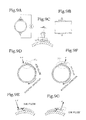
Fig. 9C shows the balance piece (35) being fixed to the propeller shaft body (22) in its width direction in a state of falling (being tilted) at an angle θ upon performing the projection welding. If the propeller shaft body (22) to which the balance piece (35) is fixed in the foregoing manner is rotated, the following problems will arise. - Foremost, let it be assumed that the propeller shaft body (22) rotates in a clockwise direction when viewed from the front in the axial direction. Meanwhile, the aerial flow of the circumferential direction of the axis will be generated in the opposite direction relative to the rotating direction of the propeller shaft body (22). If the curved plate (37) of the balance piece (35) falls to the right side relative to the perpendicular line passing through the diameter center when viewed from the front in the axial direction of the propeller shaft body (22), the aerial flow will pass above the curved plate (37) of the balance piece (35), and a load (+)F that yields pressed the surface of the left side of the curved plate (37) in the width direction toward the propeller shaft body (22) side will be applied (refer to
Fig. 9D, Fig. 9E ). - Moreover, contrarily, if the curved plate (37) of the balance piece (35) falls to the left side relative to the perpendicular line passing through the diameter center when viewed from the front in the axial direction of the propeller shaft body (22), the aerial flow will enter the back face on the right side of the curved plate (37) in the width direction and flow in a manner of colliding with the rear surface side of the curved plate (37), generate an air swirl, this becomes wind pressure resistance, and a load (-)F that attempts to peel the balance piece (35) from the propeller shaft body (22) is applied (refer to
Fig. 9F, Fig. 9G ). - Thus, with the balance piece (35), since the protruding parts (38) are formed in a single line along its longitudinal direction, and the column direction of the protruding parts (38) is along the axial direction of the propeller shaft body (22), regardless of whether the balance piece (35) falls toward the left or right when viewed from the front in the axial direction of the propeller shaft body (22), either the foregoing load (+) F or (-)F will be applied, and the balance piece (35) will be easily subject to rattling due to the vibration of the curved plate (37) since both ends of the curved plate (37) in the width direction are in a free state (refer to
Fig. 9E, Fig. 9G ). - Next, Japanese Utility Model Laid-open Publication No.
S55-61637 - Thus, since the wind pressure will directly hit the balancing weight (4), there is a possibility that wind roars will occur or that the balancing weight (4) will become air resistance. In addition, if the balancing weight (4) is simply fixed to the tip of the protruding line (3c), since the tip side will be heavier, the balancing weight (4) will sway like a see - saw from the root of the protruding line (3c), and may become the source of generating noise. This is a phenomenon that occurs because the propeller shaft rotates at high speed and the wind pressure hits directly at a random size and direction. Moreover, since the rotating speed of the propeller shaft increases and decreases at random, the swaying of the balancing weight (4) will also be random.
- Thus, an object (technical objective) of this invention is to secure a considerable amount of correction of unbalance of the shaft, reduce the generation of wind roar, air resistance, noise and the like while the motorcycle is running, and prevent the adverse effect of welding heat caused by welding and fixing the balance weight from exerting on a vibration absorbing rubber member upon correcting an unbalance of a propeller shaft for transmitting drive force to the rear wheel of a motorcycle.
- Thus, as a result of intense study to overcome the foregoing problems, the present inventors resolved the foregoing problems by configuring the invention of an unbalance correction device of a propeller shaft comprising a propeller shaft configured by a plurality of annular dampers being elastic members mounted along an axial direction between a metallic outer shaft and a metallic inner shaft, and a balance weight in which a primary weight plate part and an auxiliary weight plate part that are formed in an arc along a width direction and have a substantially quadrilateral planar shape are formed continuously and integrally along a longitudinal direction, and a protruding piece is protrusively formed on a concave arced surface on a rear surface side of the primary weight plate part and from each corner part at four locations, wherein the primary weight plate part is disposed in a non-mounted area of the dampers at an axial direction end of the outer shaft with a longitudinal direction of the balance weight coinciding with an axial direction of the outer shaft, and the balance weight is configured such that only the protruding piece comes in contact with and is welded to an outer peripheral side face of the outer shaft.
- As a result of a protruding piece being protrusively formed on a concave arced surface on a rear surface side of the weight plate part and from each corner part at four locations in the balance weight, the primary weight plate part of the balance weight will be in a four-point contact state relative to the outer peripheral side face of the outer shaft of the propeller shaft, and the balance weight can be installed in an extremely stable state on the propeller shaft, and in particular, upon performing projection welding, the balance weight can be fixed to the propeller shaft with projection welding extremely accurately due to the foregoing stability.
- The area where the balance weight can be welded in the axial direction of the propeller shaft is limited to a range at an end of the axial direction to which an elastic member is not mounted. However, as a result of configuring the size of the primary weight plate part of the balance weight to be a width that will fit within an area to which the elastic member is not mounted, the protruding piece formed at the corner part of four locations of the primary weight plate part will be positioned with a non-mounted area. Accordingly, even if the protruding piece is projection-welded to the outer shaft of the propeller shaft, the welding heat will not reach the elastic member easily, and no adverse effect will be inflicted.
- In addition, the weight of the balance weight can be sufficiently secured with the auxiliary weight plate part of the balance weight, and, since the auxiliary weight plate part is formed continuously and integrally with the primary weight plate part, it will not come in contact with the outer shaft at all and is not projection-welded with the outer shaft. Thus, even if the auxiliary weight plate part overlaps with the mounting area of the damper, the unbalance can be corrected without any welding heat being transmitted thereto. In the balance weight, as a result of preparing the auxiliary weight plate parts in various sizes as necessary, the unbalance can be corrected in an even broader range.
- Since the axial direction of the shaft and the direction (alignment direction) in which the primary weight plate part and the auxiliary weight plate part of the balance weight are formed continuously coincide and the auxiliary weight plate part always fits in the axial direction, the wind pressure resistance during the rotating motion of the propeller shaft can be reduced. Similarly, when viewed from the front in a state where the propeller shaft is mounted on a motorcycle, the portions that will be subject to wind pressure are only the plate thickness portions of the primary weight plate part and the auxiliary weight plate part of the balance weight, and, therefore, the amount of air resistance caused by the balance weight can be minimized, and the wind roar in the traveling direction of the motorcycle will hardly occur.
- Preferably, the auxiliary weight plate part has a width direction dimension that is smaller than the primary weight plate part. Since the auxiliary weight plate part has a width direction dimension that is smaller than the primary weight plate part, the wind pressure resistance of the auxiliary weight plate part of the balance weight in the rotating direction of the propeller shaft can be reduced. In particular, since the auxiliary weight plate part will not protrude in the width direction relative to the primary weight plate part other than the plate thickness portion during the rotation of the propeller shaft, the auxiliary weight plate part will only be subject to air resistance for such plate thickness portion even when viewed from the front side in the axial direction of the propeller shaft. Accordingly, a phenomenon where the auxiliary weight plate part vibrates and makes noise due to the wind pressure from the front side in the axial direction of the propeller shaft will not occur easily.
- The auxiliary weight plate part may be formed such that the wall thickness thereof gradually becomes thinner as the auxiliary weight plate part becomes separated from an end of the primary weight plate part. Since the auxiliary weight plate part is formed such that the wall thickness thereof gradually becomes thinner as the auxiliary weight plate part becomes separated from an end of the primary weight plate part, the aerial flow is distributed to the front surface side and the rear surface side of the balance weight, and the flow of the wind will converge smoothly. It is thereby possible to reduce the wind roar even further. In addition, at the end of the auxiliary weight plate part, since the flow of the once distributed air converges smoothly and the air resistance can be reduced even further, it is possible to reduce the loss of the running energy of the motorcycle.
- In addition, since the auxiliary weight plate part becomes thinner as it extends from the primary weight plate part to the tip part, the gap between the auxiliary weight plate part and the outer peripheral side face of the outer shaft becomes greater as it extends toward the tip of the auxiliary weight plate part. Thus, it becomes even more difficult for the auxiliary weight plate part and the outer shaft to come in contact during the projection welding, and it is possible to reliably perform projection welding only to the protruding piece of the primary weight plate part.
- In some examples, a curvature radius of a rear surface side of the primary weight plate part is greater than a radius of the outer shaft, and the center of the curvature radius of the rear surface side of the primary weight plate part coincides with the center of the radius of the outer shaft in a state where the balance weight is disposed on the outer peripheral side face of the outer shaft. The gap between the rear surface side of the primary weight plate part of the balance weight and the outer peripheral side face of the outer shaft of the propeller shaft will become equal (or even) at either position. Thus, the aerial flow in the circumferential direction of the axis when the propeller shaft rotates at high speed will flow regularly in a general laminar flow between the rear surface side of the primary weight plate part of the balance weight and the outer peripheral side face of the outer shaft, whereby turbulence and air resistance will not occur easily.
- Moreover, since the balance weight is subject to plastic deformation so that the corner part at the four locations of the primary weight plate part protrudes toward the rear surface side in the process of being manufactured by press working, the protruding piece can be simultaneously formed, and the manufacturing efficiency can thereby be improved. A shape of a contact surface with the outer peripheral side face of the outer shaft in the protruding piece may be a triangular shape.
- Since a shape of a contact surface with an outer peripheral side face of the outer shaft in the protruding piece is a triangular shape, the compatibility during the contact with the outer peripheral side face of the outer shaft of the propeller shaft becomes favorable.
- Some examples of devices according to the invention will now be described with reference to the accompanying drawings, in which:-
-
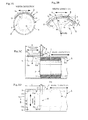
Fig. 1A is a schematic plan view of a state where the propeller shaft of the present invention is mounted on a motorcycle,Fig. 1B is a plan view of a state where the outer shaft and the inner shaft are partially cut out, andFig. 1C is a cross sectional plan view of the outer shaft and the inner shaft; -
Fig. 2A is a plan view of the balance weight,Fig. 2B is a front view of the balance weight,Fig. 2C is a rear view of the balance weight,Fig. 2D is a cross section of arrow Xa-Xa ofFig. 2B, Fig. 2E is a cross section of arrow Xb-Xb ofFig. 2A, Fig. 2F is a perspective view of the balance weight,Fig. 2G is a perspective view seen from the rear surface side of the balance weight, andFig. 2H is an enlarged view of section (a) ofFig. 2G ; -
Fig. 3A is a longitudinal front view of a state where the balance weight is projection-welded to the outer shaft of the propeller shaft,Fig. 3B is an enlarged view of the relevant part ofFig. 3A, Fig. 3C is a longitudinal side view of the relevant part of a state where the balance weight is projection-welded to the outer shaft of the propeller shaft, andFig. 3D is a plan view showing the contact state of the outer shaft and the protruding piece of the balance weight; -
Fig. 4A is an enlarged cross section of the relevant part showing the mounted state of the outer shaft and the balance weight,Fig. 4B is a cross section of arrow Xc-Xc ofFig. 4A, and Fig. 4C is an enlarged cross section of the relevant part where the projection-welded electrode comes in contact with the balance weight; -
Fig. 5A is a front view showing the rotating direction in the rotating motion of the propeller shaft mounted with the balance weight and the flow direction of the aerial flow,Fig. 5B is an enlarged view of the relevant part ofFig. 5A, and Fig. 5C is a cross section of arrow Xd-Xd ofFig. 5B ; -
Fig. 6A is a plan view in which the dimension of the auxiliary weight plate part of the balance weight is increased, andFig. 6B is a plan view in which the dimension of the auxiliary weight plate part of the balance weight is decreased; -
Fig. 7A is a rear view of a type in which the shape of the contact surface of the protruding piece is a substantially quadrilateral shape,Fig. 7B is an enlarged view of section (b) ofFig. 7A, Fig. 7C is a rear view of a type in which the shape of the contact surface of the protruding piece is a general oval shape, andFig. 7D is an enlarged view of section (c) ofFig. 7C ; -
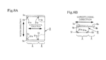
Fig. 8A is a rear view of a type in which the width direction dimension of the primary weight plate part and the width direction dimension of the auxiliary weight plate part are the same, andFig. 8B is a longitudinal side view of the balance weight of a type in which the wall thickness of the auxiliary weight plate part is uniform, and a rear view of a type in which the shape of the contact surface of the protruding piece is a general triangular shape; and -
Fig. 9A is a longitudinal front view of the conventional technology,Fig. 9B is a longitudinal side view of the relevant part of the conventional technology,Fig. 9C is an enlarged front view of the relevant part showing a state where the balance piece is projection-welded in a fallen state in the conventional technology,Fig. 9D is a longitudinal front view of a state where the balance piece has fallen toward the right side,Fig. 9E is an enlarged view of section (d) ofFig. 9D, Fig. 9F is a longitudinal front view of a state where the balance piece has fallen toward the left side, andFig. 9G is an enlarged view of section (e) ofFig. 9F .- A
- Propeller shaft
- 1
- Outer shaft
- 1a
- Outer peripheral side face
- 2
- Inner shaft
- 3
- Damper
- B
- Balance weight
- 5
- Primary weight plate part
- 5b
- Rear surface side
- 51
- Protruding piece
- 6
- Auxiliary weight plate part
- R5
- Curvature radius
- The propeller shaft A of the present invention, as shown in
Fig. 1A , is a component for transmitting the power transmitted from the engine to the rear wheel in a motorcycle via a transmission and a clutch. The propeller shaft A is disposed between the engine and the rear wheel, and arranged so that the traveling direction of the motorcycle and the axial direction of the propeller shaft A, or the axial direction of the propeller shaft A and the front/back direction of the motorcycle coincide. In other words, the propeller shaft A is disposed such that its axial direction is along the traveling direction of the motorcycle. The propeller shaft A is configured, as shown inFig. 1B and Fig. 1C , mainly from anouter shaft 1, aninner shaft 2, adamper 3 and ayoke joint 4. - The
outer shaft 1 and theinner shaft 2 are made of metal; specifically, made of an iron material. Theouter shaft 1 is formed in a hollow shape, and theinner shaft 2 is housed in theouter shaft 1. Theinner shaft 2 is configured from a housedaxis part 21 and anoutput axis part 22, and the housedaxis part 21 is housed inside theouter shaft 1. Theoutput axis part 22 is an axis that is exposed to the outside. Theoutput axis part 22 is actually formed to be longer than theouter shaft 1 in the axial direction (refer toFig. 1A ). - As shown in
Fig. 1C , adamper 3 is mounted between an innerperipheral side face 1b of theouter shaft 1 and an outerperipheral side face 21a of the housedaxis part 21 of theinner shaft 2. Thedamper 3 is mounted by being lightly press-fitted and bonded to a gap between the outerperipheral side face 21a of the housedaxis part 21 of theinner shaft 2 and the innerperipheral side face 1b of theouter shaft 1. Thedamper 3 is an elastic member formed in a general flat cylindrical annular (or ring) shape, and specifically a round rubber material is used. - The outer periphery side of the
damper 3 is closely attached to the innerperipheral side face 1b of theouter shaft 1, and the inner periphery side of thedamper 3 is closely attached to the outerperipheral side face 21a of the housedaxis part 21 of theinner shaft 2. The housedaxis part 21 of theinner shaft 2 transmits the rotary torque from thedamper 3 to theoutput axis part 22. Thedamper 3 has a function of blocking the rotational vibration from the propeller shaft A, but the rotary torque is transmitted in its entirety. Specifically, thedamper 3 and the housedaxis part 21 of theinner shaft 2 housed on the inner periphery side of theouter shaft 1 rotate in synch at the same rotation speed. - With this structure, the
damper 3 functions to solidly connect and fix theouter shaft 1 and theinner shaft 2, and reduce the vibration generated upon transmitting the rotation from theouter shaft 1 to theinner shaft 2 by absorbing such vibration. In the present invention, thedampers 3 are disposed in five columns along the axial direction of theouter shaft 1 and the inner shaft 2 (refer toFig. 1C ). Ayoke joint 4 is mounted at the axial end part of the outer shaft 1 (refer toFig. 1B, Fig. 1C ). Theyoke joint 4 is mounted at the front side end of the propeller shaft A in the axial direction, and receives the rotation from the engine (refer toFig. 1A ) . Theyoke joint 4 has the function of being able to transmit the rotary torque even if it is not aligned in a straight line along the axial direction of the propeller shaft A. - The balance weight B is now explained. The balance weight B corrects the unbalance of the propeller shaft A, and functions to ensure a favorable rotating motion without hardly any swaying (refer to
Fig. 1B ) . The balance weights B are mounted on the propeller shaft A at two locations at most, but if the unbalance can be resolved by correcting the unbalance only by mounting the balance weight B at one location, then the balance weight B only needs to be mounted at one location. - The balance weight B is formed by press working a plate-shaped steel material. The balance weight B is configured, as shown in
Fig. 2A, Fig. 2C, Fig. 2D, Fig. 2F and the like, from a primaryweight plate part 5 and an auxiliaryweight plate part 6. The primaryweight plate part 5 and the auxiliaryweight plate part 6 are formed continuously and integrally in a single line as shown inFig. 2A and Fig. 2C . The direction in which the primaryweight plate part 5 and the auxiliaryweight plate part 6 are formed in a line shall be the longitudinal direction of the balance weight B (refer toFig. 2B, Fig. 2C ). - Moreover, with width direction of the balance weight B shall be a direction that is orthogonal to the foregoing longitudinal direction (refer to
Fig. 2B, Fig. 2C ). The primaryweight plate part 5 is shaped by a plate material of a substantially quadrilateral shape such as a rectangle or a square being bent and formed in an arc. The primaryweight plate part 5 is provided with afront surface side 5a and arear surface side 5b, and thefront surface side 5a is a convex surface and therear surface side 5b is a concave surface (refer toFig. 2B, Fig. 2D ). Protrudingpieces corner parts rear surface side 5b of the primaryweight plate part 5 formed in a substantially quadrilateral shape (refer toFig. 2B, Fig. 2C, Fig. 2D ). - The
corner parts 5c are external corner parts as shown inFig. 2C , and become the four corners of the quadrilateral primaryweight plate part 5. Specifically, the balance weight B is projection-welded with the four protrudingpieces outer shaft 1 since the protrudingpieces weight plate part 5 in the width direction, and can be mounted stably on the outerperipheral side face 1a of theouter shaft 1, and can be fixed in an extremely stable manner in both the longitudinal direction (axial direction of the outer shaft 1) and the width direction (circumferential direction of the axis of the outer shaft 1) (refer toFig. 3 ). - The protruding direction of the protruding
piece 51 is a direction facing the center P5 of the curvature radius R5 of therear surface side 5b of the primary weight plate part 5 (refer toFig. 2B ). However, the protruding direction of the protrudingpiece 51 may also be parallel from thecorner parts weight plate part 5. The protrudingpiece 51 is a part that comes in contact with the outerperipheral side face 1a of theouter shaft 1 of the propeller shaft A, and the shape of thecontact surface 51a to come in contact with the outerperipheral side face 1a of theouter shaft 1 in the protrudingpiece 51 is a general triangular shape (refer toFig. 2C, Fig. 2D, Fig. 2H , etc.). - Moreover, the
contact surface 51a may also be formed in a substantially quadrilateral shape such as a rectangle or a square (refer toFig. 7A, Fig. 7B ), or formed in a circle or an oval shape (refer toFig. 7C, Fig. 7D ). The balance weight B is formed by press working as described above, but the protrudingpieces 51 may also be formed by performing finish processing using the notch-shaped plastic deformation part formed at both ends of the arc-shaped primaryweight plate part 5 in the width direction at the processing step of the press forming. In particular, if the notches that arise during the processing step of the press working of the primaryweight plate part 5 of the balance weight B are used as is for forming the protrudingpieces 51, the shape of the foregoingcontact surface 51a can be made to be a general triangular shape. - The curvature radius R5 of the arc that is formed by bending the primary
weight plate part 5 is made to be the same concentric circle as the diameter center position P1 in the diameter direction of theouter shaft 1 of the propeller shaft A. Specifically, the radius center P5 of the curvature radius R5 of the primaryweight plate part 5 coincides with the position of the diameter center P1 of the outer shaft 1 (refer toFig. 3B ). In a state where the four protrudingpieces rear surface side 5b of the primaryweight plate part 5 are in contact with the outer peripheral side face of theouter shaft 1 of the propeller shaft A, the spacing t of the gap between therear surface side 5b of the primaryweight plate part 5 and the outerperipheral side face 1a of theouter shaft 1 will be the same at either position. - The curvature radius R5 of the primary
weight plate part 5 is formed to be slightly larger than the radius R1 of theouter shaft 1 of the propeller shaft A. For example, if the spacing between therear surface side 5b of the primaryweight plate part 5 and the outerperipheral side face 1a of theouter shaft 1 is 0.2 mm, it will be R5 = R1 + 0.2. In other words, a spacing t of a narrow gap is formed between the balance weight B and the hollow shaft at the outer periphery side of the propeller shaft A. - As described above, the gap t between the
rear surface side 5b of the primaryweight plate part 5 of the balance weight B and the outerperipheral side face 1a of theouter shaft 1 of the propeller shaft A will be the same (or even) at either position by causing the curvature radius R5 of the arc formed by bending the primaryweight plate part 5 to be the concentric circle as the diameter center position P1 in the diameter direction of theouter shaft 1 of the propeller shaft A. Thus, when the propeller shaft A rotates at high speed in the circumferential direction of the axis, the aerial flow in the circumferential direction of the axis will be the opposite direction of the rotating direction of the propeller shaft A (refer toFig. 5A ), the aerial flow will flow regularly in a general laminar flow between therear surface side 5b of the primaryweight plate part 5 of the balance weight B and the outerperipheral side face 1a of theouter shaft 1. Thus, the air flowing in the gap and the air flowing on the surface of the balance weight B will smoothly converge when they are to converge once again, and it will be the most difficult for air resistance to occur (refer toFig. 5B ). - The auxiliary
weight plate part 6 is configured integrally and continuously with the primaryweight plate part 5 as shown inFig. 2A, Fig. 2C, and Fig. 2D , and the width direction dimension W6 of the auxiliaryweight plate part 6 is formed to be smaller than the width direction dimension W5 of the primary weight plate part 5 (refer toFig. 2A ). Moreover, the width direction dimension W5 of the primaryweight plate part 5 and the width direction dimension W6 of the auxiliaryweight plate part 6 may also be of the same dimension (refer toFig. 8A ). The auxiliaryweight plate part 6 is formed in a quadrilateral shape such as a rectangle or a square, and is basically bent and formed in an arc in the width direction. The auxiliaryweight plate part 6 is also provided with afront surface side 6a and arear surface side 6b similar to the primaryweight plate part 5. - The auxiliary
weight plate part 6 is formed such that the thickness gradually becomes thin from its root with the primaryweight plate part 5 to the end across the axial direction as shown inFig. 2D ,Fig. 3C ,Fig. 4B and the like. However, thefront surface side 6a of the auxiliaryweight plate part 6 is of the same plane with thefront surface side 5a of the primaryweight plate part 5, and therear surface side 5b of the auxiliaryweight plate part 6 is an inclined surface. Specifically, the plate thickness is 2.9 mm at the root with the primaryweight plate part 5, and the plate thickness is thin at 2 mm at the tip part in the axial direction. Moreover, the wall thickness of the auxiliaryweight plate part 6 may also be a uniform thickness at either position (refer toFig. 8B ). - Since the wall thickness of the auxiliary
weight plate part 6 is formed to become gradually thinner as it becomes separated from the end of the primaryweight plate part 5, the aerial flow is distributed to thefront surface sides rear surface sides Fig. 5C ). Moreover, since the auxiliaryweight plate part 6 becomes thin as it extends from the primaryweight plate part 5 to the tip part, the gap between the auxiliaryweight plate part 6 and the outerperipheral side face 1a of theouter shaft 1 becomes greater as it extends toward the tip of the auxiliaryweight plate part 6. Thus, during the projection welding, it because more difficult for the auxiliaryweight plate part 6 and the outerperipheral side face 1a of theouter shaft 1 to come in contact, and it is possible to projection-weld only the protrudingpieces 51 of the primaryweight plate part 5 with accuracy. - Balance weights B of various weights may be prepared based on the different dimensions of the auxiliary
weight plate part 6. Specifically, a plurality of different balance weights B in which the auxiliaryweight plate part 6 of various sizes is prepared, and the balance weight B of the weight required for correcting the unbalance of the propeller shaft A is used. - For example, a balance weight B that is heavier than the standard balance weight B can be obtained by making the length of the auxiliary
weight plate part 6 in the longitudinal direction to be longer by ΔL relative to the balance weight B of a standard weight (refer toFig. 6A ), or a balance weight B that is lighter than the standard balance weight B can be obtained by making the length of the auxiliaryweight plate part 6 in the longitudinal direction to be shorter by ΔL relative to the balance weight B of a standard weight (refer toFig. 6B ). By appropriately selecting the balance weight B among those with various weights, the unbalance of the propeller shaft A can be corrected with precision. - Upon fixing the balance weight B upon correcting the unbalance of the propeller shaft A, the longitudinal direction of the balance weight B is made to substantially coincide with the outer
peripheral side face 1a of theouter shaft 1 configuring the propeller shaft A relative to the axial direction of the outer shaft 1 (refer toFig. 1B ,Fig. 3C, Fig. 3D ). The primaryweight plate part 5 is thereby disposed in the non-mounted area K of thedamper 3 at the axial direction end of theouter shaft 1. - The non-mounted area K is the area of the outer
peripheral side face 1a of theouter shaft 1 to which thedamper 3 is not mounted internally at the axial direction end of the outer shaft 1 (refer toFig. 1C ,Fig. 3C, Fig. 3D ). Moreover, the auxiliaryweight plate part 6 of the balance weight B is set to be positioned at the center in the axial direction of theouter shaft 1 in comparison to the primary weight plate part 5 (refer toFig. 1B ,Fig. 3C, Fig. 3D ). Specifically, the primaryweight plate part 5 of the balance weight B is constantly positioned toward the outer side in the axial direction in a state of being fixed to theouter shaft 1. - The balance weight B and the outer
peripheral side face 1a of theouter shaft 1 only come in contact at the four protrudingpieces peripheral side face 1a of theouter shaft 1 and therear surface side 5b of the primaryweight plate part 5 and therear surface side 6b of the auxiliaryweight plate part 6 of the balance weight B are separated and in a non-contact state (refer toFig. 3C, Fig. 3D ). However, the auxiliaryweight plate part 6 has an overlapping area Ka which positionally overlaps with the non-mounted area K. The overlapping area Ka is not in contact with the non-mounted area K on theperipheral side face 1a of theouter shaft 1 as described above. - The balance weight B comes in contact with the four protruding
piece outer shaft 1 of the propeller shaft A, and is welded at the welding points of the protrudingpiece peripheral side face 1a of theouter shaft 1. Projection welding is used as the welding means. The balance weight B in this invention is especially favorable for projection welding, and the four protrudingpieces weight plate part 5 of the balance weight B are arranged in a quadrilateral shape. Thus, the four protrudingpieces peripheral side face 1a of theouter shaft 1 configuring the propeller shaft A (refer toFig. 3D ), and the balance weight B can be projection-welded in a stable state without swaying in the width direction and longitudinal direction upon causing theelectrode 7 to be projected welded to come in contact with the balance weight B and the outerperipheral side face 1a of the outer shaft 1 (refer toFig. 4 ). - In a state where the balance weight B is fixed to the propeller shaft A, although it appears that a thin arc plate is in general contact with the outer
peripheral side face 1a of theouter shaft 1, in reality there is a slight gap t between the outerperipheral side face 1a of theouter shaft 1 and therear surface side 5b of the primaryweight plate part 5 and therear surface side 6b of the auxiliary weight plate part 6 (refer toFig. 3B ). The welding range to the propeller shaft A of the balance weight B will be the non-mounted area K without thedamper 3 in theouter shaft 1. - Measurement of the unbalance amount of the propeller shaft A is performed in a state when the propeller shaft A has been assembled by giving consideration to the total (overall) variation in the precision of the respective components and variation in the precision of assembly. Then, the unbalance amount (g.Cm) (N·m if in S1 units) is measures while rotating the propeller shaft at a given rotation speed (pm), and a balance weight B is selected and welded among those of various weights based on the measurement result. Consequently, the unbalance amount of the overall propeller shaft can be reduced and the swaying during the rotation can be decreased.
Claims (5)
- An unbalance correction device of a propeller shaft, comprising:a propeller shaft configured by a plurality of annular dampers being elastic members mounted along an axial direction between a metallic outer shaft and a metallic inner shaft; anda balance weight in which a primary weight plate part and an auxiliary weight plate part that are formed in an arc along a width direction and have a substantially quadrilateral planar shape are formed continuously and integrally along a longitudinal direction, and a protruding piece is protrusively formed on a concave arced surface on a rear surface side of the primary weight plate part and from each corner part at four locations,wherein the primary weight plate part is disposed in a non-mounted area of the dampers at an axial direction end of the outer shaft with a longitudinal direction of the balance weight coinciding with an axial direction of the outer shaft, and the balance weight is configured such that only the protruding piece comes in contact with and is welded to an outer peripheral side face of the outer shaft.
- The unbalance correction device of a propeller shaft according to claim 1,
wherein the auxiliary weight plate part has a width direction dimension that is smaller than the primary weight plate part. - The unbalance correction device of a propeller shaft according to claim 1 or claim 2,
wherein the auxiliary weight plate part is formed such that the wall thickness thereof gradually becomes thinner as the auxiliary weight plate part becomes separated from an end of the primary weight plate part. - The unbalance correction device of a propeller shaft according to any one of claims 1, 2 and 3,
wherein a curvature radius of a rear surface side of the primary weight plate part is greater than a radius of the outer shaft, and the center of the curvature radius of the rear surface side of the primary weight plate part coincides with the center of the radius of the outer shaft in a state where the balance weight is disposed on the outer peripheral side face of the outer shaft. - The unbalance correction device of a propeller shaft according to any one of claims 1, 2, 3 and 4,
wherein a shape of a contact surface with the outer peripheral side face of the outer shaft in the protruding piece is a triangular shape.
Applications Claiming Priority (1)
| Application Number | Priority Date | Filing Date | Title |
|---|---|---|---|
| JP2009225614A JP5340098B2 (en) | 2009-09-29 | 2009-09-29 | Propeller shaft unbalance correction device |
Publications (3)
| Publication Number | Publication Date |
|---|---|
| EP2302256A2 true EP2302256A2 (en) | 2011-03-30 |
| EP2302256A3 EP2302256A3 (en) | 2011-11-23 |
| EP2302256B1 EP2302256B1 (en) | 2012-12-26 |
Family
ID=43303811
Family Applications (1)
| Application Number | Title | Priority Date | Filing Date |
|---|---|---|---|
| EP10175630A Not-in-force EP2302256B1 (en) | 2009-09-29 | 2010-09-07 | Unbalance correction device of propeller shaft |
Country Status (4)
| Country | Link |
|---|---|
| US (1) | US8376866B2 (en) |
| EP (1) | EP2302256B1 (en) |
| JP (1) | JP5340098B2 (en) |
| CN (1) | CN102032317A (en) |
Families Citing this family (6)
| Publication number | Priority date | Publication date | Assignee | Title |
|---|---|---|---|---|
| CN103244572B (en) * | 2012-02-14 | 2016-05-18 | 上海海马汽车研发有限公司 | Torsion damping power transmission shaft |
| US9512728B2 (en) | 2013-04-26 | 2016-12-06 | Hamilton Sundstrand Corporation | Simplified propeller balancing system and method |
| EP3156158A4 (en) | 2014-09-09 | 2018-03-07 | IHI Corporation | Hollow rotating shaft-finishing method and hollow rotating shaft |
| WO2016154239A1 (en) * | 2015-03-26 | 2016-09-29 | Dana Automotive Systems Group, Llc | Laser welding of balance weights to driveshafts |
| KR102366548B1 (en) * | 2017-06-30 | 2022-02-23 | 히다치 아스테모 가부시키가이샤 | Power transmission shaft and method for manufacturing same |
| JP7090876B2 (en) * | 2018-02-02 | 2022-06-27 | 株式会社松井製作所 | Manufacturing method of balance weight, rotary shaft with balance weight and rotary shaft with balance weight |
Citations (2)
| Publication number | Priority date | Publication date | Assignee | Title |
|---|---|---|---|---|
| JPS5561637U (en) | 1978-10-24 | 1980-04-26 | ||
| JPH0594555U (en) | 1992-05-26 | 1993-12-24 | 三菱自動車工業株式会社 | Propeller shaft |
Family Cites Families (11)
| Publication number | Priority date | Publication date | Assignee | Title |
|---|---|---|---|---|
| US3940948A (en) * | 1973-09-27 | 1976-03-02 | Gelenkwellenbau Gmbh | Universal joint shaft |
| DE3011824C2 (en) * | 1980-03-27 | 1983-06-01 | Bayerische Motoren Werke AG, 8000 München | Method for welding a balance weight having claw-like extensions on its support surface to a cardan shaft and balance weight |
| JP2532365Y2 (en) * | 1988-04-18 | 1997-04-16 | トヨタ自動車株式会社 | Rotary shaft damper |
| DE3906114C1 (en) * | 1989-02-28 | 1990-06-13 | Gkn Cardantec International Gesellschaft Fuer Antriebstechnik Mbh, 4300 Essen, De | |
| DE3931055A1 (en) * | 1989-09-18 | 1991-03-28 | Gkn Cardantec | BALANCE WEIGHT FOR UNIVERSAL SHAFT |
| JPH04107340A (en) * | 1990-08-29 | 1992-04-08 | Kinugawa Rubber Ind Co Ltd | Propeller shaft |
| JPH0471842U (en) * | 1990-10-29 | 1992-06-25 | ||
| GB2272041B (en) * | 1992-10-28 | 1995-10-25 | Unidrive Pty Ltd | Propeller shafts |
| JP2000320529A (en) * | 1999-05-13 | 2000-11-24 | Tokai Rubber Ind Ltd | Propeller shaft |
| US6701802B2 (en) * | 2001-12-13 | 2004-03-09 | Visteon Global Technologies, Inc. | Balancing weight for a rotating shaft |
| JP4994071B2 (en) * | 2007-03-20 | 2012-08-08 | 本田技研工業株式会社 | Motorcycle shaft drive device |
-
2009
- 2009-09-29 JP JP2009225614A patent/JP5340098B2/en active Active
-
2010
- 2010-09-07 EP EP10175630A patent/EP2302256B1/en not_active Not-in-force
- 2010-09-22 US US12/923,449 patent/US8376866B2/en not_active Expired - Fee Related
- 2010-09-27 CN CN201010298268XA patent/CN102032317A/en active Pending
Patent Citations (2)
| Publication number | Priority date | Publication date | Assignee | Title |
|---|---|---|---|---|
| JPS5561637U (en) | 1978-10-24 | 1980-04-26 | ||
| JPH0594555U (en) | 1992-05-26 | 1993-12-24 | 三菱自動車工業株式会社 | Propeller shaft |
Also Published As
| Publication number | Publication date |
|---|---|
| CN102032317A (en) | 2011-04-27 |
| EP2302256B1 (en) | 2012-12-26 |
| JP5340098B2 (en) | 2013-11-13 |
| US20110077092A1 (en) | 2011-03-31 |
| EP2302256A3 (en) | 2011-11-23 |
| US8376866B2 (en) | 2013-02-19 |
| JP2011073525A (en) | 2011-04-14 |
Similar Documents
| Publication | Publication Date | Title |
|---|---|---|
| EP2302256B1 (en) | Unbalance correction device of propeller shaft | |
| CN103261733B (en) | Centrifugal force pendulum device | |
| AU2006201483B2 (en) | Impact tool | |
| US9787163B2 (en) | Rotor of an electrical machine and electrical machine | |
| WO2021027733A1 (en) | Centrifugal force pendulum, torque transmission device comprising the centrifugal force pendulum, and vehicle | |
| US9926993B2 (en) | Coil spring | |
| JP2009281487A (en) | Connection structure of crankshaft and rotary member | |
| JP3893478B2 (en) | Wheel balance weight | |
| CN110869631A (en) | Cross joints and drive shafts | |
| JPWO2006098254A1 (en) | Blade and fan with this blade | |
| US7775335B2 (en) | Torque transmitting device | |
| JP3160223B2 (en) | Vehicle drive plate | |
| JP6573824B2 (en) | Diaphragm coupling | |
| CN112696459B (en) | Centrifugal pendulum | |
| JP2006342886A (en) | Flexible shaft coupling | |
| JP7162913B2 (en) | shaft coupling | |
| JP5573670B2 (en) | Centrifugal pendulum vibration absorber | |
| JP2011247353A (en) | Yoke for universal joint and universal joint having the same | |
| CN214743036U (en) | Novel dynamic balance sheet | |
| WO2018151653A1 (en) | Coupling disc | |
| KR100925751B1 (en) | Wheel bearing hub | |
| JP2015215042A (en) | Buffer member of torque transmission joint | |
| CN221462840U (en) | Damping component and damping device | |
| US20090247308A1 (en) | Universal joint | |
| JP7341316B2 (en) | Torque converters and vehicles containing torque converters |
Legal Events
| Date | Code | Title | Description |
|---|---|---|---|
| PUAI | Public reference made under article 153(3) epc to a published international application that has entered the european phase |
Free format text: ORIGINAL CODE: 0009012 |
|
| AK | Designated contracting states |
Kind code of ref document: A2 Designated state(s): AL AT BE BG CH CY CZ DE DK EE ES FI FR GB GR HR HU IE IS IT LI LT LU LV MC MK MT NL NO PL PT RO SE SI SK SM TR |
|
| AX | Request for extension of the european patent |
Extension state: BA ME RS |
|
| PUAL | Search report despatched |
Free format text: ORIGINAL CODE: 0009013 |
|
| AK | Designated contracting states |
Kind code of ref document: A3 Designated state(s): AL AT BE BG CH CY CZ DE DK EE ES FI FR GB GR HR HU IE IS IT LI LT LU LV MC MK MT NL NO PL PT RO SE SI SK SM TR |
|
| AX | Request for extension of the european patent |
Extension state: BA ME RS |
|
| RIC1 | Information provided on ipc code assigned before grant |
Ipc: F16F 15/32 20060101AFI20111020BHEP |
|
| 17P | Request for examination filed |
Effective date: 20120419 |
|
| GRAJ | Information related to disapproval of communication of intention to grant by the applicant or resumption of examination proceedings by the epo deleted |
Free format text: ORIGINAL CODE: EPIDOSDIGR1 |
|
| GRAP | Despatch of communication of intention to grant a patent |
Free format text: ORIGINAL CODE: EPIDOSNIGR1 |
|
| GRAP | Despatch of communication of intention to grant a patent |
Free format text: ORIGINAL CODE: EPIDOSNIGR1 |
|
| GRAS | Grant fee paid |
Free format text: ORIGINAL CODE: EPIDOSNIGR3 |
|
| GRAA | (expected) grant |
Free format text: ORIGINAL CODE: 0009210 |
|
| AK | Designated contracting states |
Kind code of ref document: B1 Designated state(s): AL AT BE BG CH CY CZ DE DK EE ES FI FR GB GR HR HU IE IS IT LI LT LU LV MC MK MT NL NO PL PT RO SE SI SK SM TR |
|
| REG | Reference to a national code |
Ref country code: GB Ref legal event code: FG4D |
|
| REG | Reference to a national code |
Ref country code: CH Ref legal event code: EP |
|
| REG | Reference to a national code |
Ref country code: AT Ref legal event code: REF Ref document number: 590658 Country of ref document: AT Kind code of ref document: T Effective date: 20130115 |
|
| REG | Reference to a national code |
Ref country code: DE Ref legal event code: R096 Ref document number: 602010004292 Country of ref document: DE Effective date: 20130307 |
|
| PG25 | Lapsed in a contracting state [announced via postgrant information from national office to epo] |
Ref country code: LT Free format text: LAPSE BECAUSE OF FAILURE TO SUBMIT A TRANSLATION OF THE DESCRIPTION OR TO PAY THE FEE WITHIN THE PRESCRIBED TIME-LIMIT Effective date: 20121226 Ref country code: NO Free format text: LAPSE BECAUSE OF FAILURE TO SUBMIT A TRANSLATION OF THE DESCRIPTION OR TO PAY THE FEE WITHIN THE PRESCRIBED TIME-LIMIT Effective date: 20130326 Ref country code: SE Free format text: LAPSE BECAUSE OF FAILURE TO SUBMIT A TRANSLATION OF THE DESCRIPTION OR TO PAY THE FEE WITHIN THE PRESCRIBED TIME-LIMIT Effective date: 20121226 Ref country code: HR Free format text: LAPSE BECAUSE OF FAILURE TO SUBMIT A TRANSLATION OF THE DESCRIPTION OR TO PAY THE FEE WITHIN THE PRESCRIBED TIME-LIMIT Effective date: 20121226 Ref country code: FI Free format text: LAPSE BECAUSE OF FAILURE TO SUBMIT A TRANSLATION OF THE DESCRIPTION OR TO PAY THE FEE WITHIN THE PRESCRIBED TIME-LIMIT Effective date: 20121226 |
|
| REG | Reference to a national code |
Ref country code: AT Ref legal event code: MK05 Ref document number: 590658 Country of ref document: AT Kind code of ref document: T Effective date: 20121226 |
|
| REG | Reference to a national code |
Ref country code: LT Ref legal event code: MG4D |
|
| REG | Reference to a national code |
Ref country code: NL Ref legal event code: VDEP Effective date: 20121226 |
|
| PG25 | Lapsed in a contracting state [announced via postgrant information from national office to epo] |
Ref country code: LV Free format text: LAPSE BECAUSE OF FAILURE TO SUBMIT A TRANSLATION OF THE DESCRIPTION OR TO PAY THE FEE WITHIN THE PRESCRIBED TIME-LIMIT Effective date: 20121226 Ref country code: SI Free format text: LAPSE BECAUSE OF FAILURE TO SUBMIT A TRANSLATION OF THE DESCRIPTION OR TO PAY THE FEE WITHIN THE PRESCRIBED TIME-LIMIT Effective date: 20121226 Ref country code: GR Free format text: LAPSE BECAUSE OF FAILURE TO SUBMIT A TRANSLATION OF THE DESCRIPTION OR TO PAY THE FEE WITHIN THE PRESCRIBED TIME-LIMIT Effective date: 20130327 |
|
| PG25 | Lapsed in a contracting state [announced via postgrant information from national office to epo] |
Ref country code: AT Free format text: LAPSE BECAUSE OF FAILURE TO SUBMIT A TRANSLATION OF THE DESCRIPTION OR TO PAY THE FEE WITHIN THE PRESCRIBED TIME-LIMIT Effective date: 20121226 Ref country code: SK Free format text: LAPSE BECAUSE OF FAILURE TO SUBMIT A TRANSLATION OF THE DESCRIPTION OR TO PAY THE FEE WITHIN THE PRESCRIBED TIME-LIMIT Effective date: 20121226 Ref country code: BE Free format text: LAPSE BECAUSE OF FAILURE TO SUBMIT A TRANSLATION OF THE DESCRIPTION OR TO PAY THE FEE WITHIN THE PRESCRIBED TIME-LIMIT Effective date: 20121226 Ref country code: ES Free format text: LAPSE BECAUSE OF FAILURE TO SUBMIT A TRANSLATION OF THE DESCRIPTION OR TO PAY THE FEE WITHIN THE PRESCRIBED TIME-LIMIT Effective date: 20130406 Ref country code: BG Free format text: LAPSE BECAUSE OF FAILURE TO SUBMIT A TRANSLATION OF THE DESCRIPTION OR TO PAY THE FEE WITHIN THE PRESCRIBED TIME-LIMIT Effective date: 20130326 Ref country code: CZ Free format text: LAPSE BECAUSE OF FAILURE TO SUBMIT A TRANSLATION OF THE DESCRIPTION OR TO PAY THE FEE WITHIN THE PRESCRIBED TIME-LIMIT Effective date: 20121226 Ref country code: IS Free format text: LAPSE BECAUSE OF FAILURE TO SUBMIT A TRANSLATION OF THE DESCRIPTION OR TO PAY THE FEE WITHIN THE PRESCRIBED TIME-LIMIT Effective date: 20130426 Ref country code: EE Free format text: LAPSE BECAUSE OF FAILURE TO SUBMIT A TRANSLATION OF THE DESCRIPTION OR TO PAY THE FEE WITHIN THE PRESCRIBED TIME-LIMIT Effective date: 20121226 |
|
| PG25 | Lapsed in a contracting state [announced via postgrant information from national office to epo] |
Ref country code: RO Free format text: LAPSE BECAUSE OF FAILURE TO SUBMIT A TRANSLATION OF THE DESCRIPTION OR TO PAY THE FEE WITHIN THE PRESCRIBED TIME-LIMIT Effective date: 20121226 Ref country code: NL Free format text: LAPSE BECAUSE OF FAILURE TO SUBMIT A TRANSLATION OF THE DESCRIPTION OR TO PAY THE FEE WITHIN THE PRESCRIBED TIME-LIMIT Effective date: 20121226 Ref country code: PL Free format text: LAPSE BECAUSE OF FAILURE TO SUBMIT A TRANSLATION OF THE DESCRIPTION OR TO PAY THE FEE WITHIN THE PRESCRIBED TIME-LIMIT Effective date: 20121226 Ref country code: PT Free format text: LAPSE BECAUSE OF FAILURE TO SUBMIT A TRANSLATION OF THE DESCRIPTION OR TO PAY THE FEE WITHIN THE PRESCRIBED TIME-LIMIT Effective date: 20130426 |
|
| PG25 | Lapsed in a contracting state [announced via postgrant information from national office to epo] |
Ref country code: DK Free format text: LAPSE BECAUSE OF FAILURE TO SUBMIT A TRANSLATION OF THE DESCRIPTION OR TO PAY THE FEE WITHIN THE PRESCRIBED TIME-LIMIT Effective date: 20121226 |
|
| PLBE | No opposition filed within time limit |
Free format text: ORIGINAL CODE: 0009261 |
|
| STAA | Information on the status of an ep patent application or granted ep patent |
Free format text: STATUS: NO OPPOSITION FILED WITHIN TIME LIMIT |
|
| PG25 | Lapsed in a contracting state [announced via postgrant information from national office to epo] |
Ref country code: CY Free format text: LAPSE BECAUSE OF FAILURE TO SUBMIT A TRANSLATION OF THE DESCRIPTION OR TO PAY THE FEE WITHIN THE PRESCRIBED TIME-LIMIT Effective date: 20121226 |
|
| 26N | No opposition filed |
Effective date: 20130927 |
|
| REG | Reference to a national code |
Ref country code: DE Ref legal event code: R097 Ref document number: 602010004292 Country of ref document: DE Effective date: 20130927 |
|
| PG25 | Lapsed in a contracting state [announced via postgrant information from national office to epo] |
Ref country code: MC Free format text: LAPSE BECAUSE OF FAILURE TO SUBMIT A TRANSLATION OF THE DESCRIPTION OR TO PAY THE FEE WITHIN THE PRESCRIBED TIME-LIMIT Effective date: 20121226 |
|
| REG | Reference to a national code |
Ref country code: FR Ref legal event code: ST Effective date: 20140530 |
|
| REG | Reference to a national code |
Ref country code: IE Ref legal event code: MM4A |
|
| PG25 | Lapsed in a contracting state [announced via postgrant information from national office to epo] |
Ref country code: IE Free format text: LAPSE BECAUSE OF NON-PAYMENT OF DUE FEES Effective date: 20130907 |
|
| PG25 | Lapsed in a contracting state [announced via postgrant information from national office to epo] |
Ref country code: FR Free format text: LAPSE BECAUSE OF NON-PAYMENT OF DUE FEES Effective date: 20130930 |
|
| PGFP | Annual fee paid to national office [announced via postgrant information from national office to epo] |
Ref country code: IT Payment date: 20140915 Year of fee payment: 5 |
|
| REG | Reference to a national code |
Ref country code: CH Ref legal event code: PL |
|
| GBPC | Gb: european patent ceased through non-payment of renewal fee |
Effective date: 20140907 |
|
| PG25 | Lapsed in a contracting state [announced via postgrant information from national office to epo] |
Ref country code: SM Free format text: LAPSE BECAUSE OF FAILURE TO SUBMIT A TRANSLATION OF THE DESCRIPTION OR TO PAY THE FEE WITHIN THE PRESCRIBED TIME-LIMIT Effective date: 20121226 |
|
| PG25 | Lapsed in a contracting state [announced via postgrant information from national office to epo] |
Ref country code: MT Free format text: LAPSE BECAUSE OF FAILURE TO SUBMIT A TRANSLATION OF THE DESCRIPTION OR TO PAY THE FEE WITHIN THE PRESCRIBED TIME-LIMIT Effective date: 20121226 Ref country code: TR Free format text: LAPSE BECAUSE OF FAILURE TO SUBMIT A TRANSLATION OF THE DESCRIPTION OR TO PAY THE FEE WITHIN THE PRESCRIBED TIME-LIMIT Effective date: 20121226 |
|
| PG25 | Lapsed in a contracting state [announced via postgrant information from national office to epo] |
Ref country code: LU Free format text: LAPSE BECAUSE OF NON-PAYMENT OF DUE FEES Effective date: 20130907 Ref country code: CH Free format text: LAPSE BECAUSE OF NON-PAYMENT OF DUE FEES Effective date: 20140930 Ref country code: MK Free format text: LAPSE BECAUSE OF FAILURE TO SUBMIT A TRANSLATION OF THE DESCRIPTION OR TO PAY THE FEE WITHIN THE PRESCRIBED TIME-LIMIT Effective date: 20121226 Ref country code: LI Free format text: LAPSE BECAUSE OF NON-PAYMENT OF DUE FEES Effective date: 20140930 Ref country code: HU Free format text: LAPSE BECAUSE OF FAILURE TO SUBMIT A TRANSLATION OF THE DESCRIPTION OR TO PAY THE FEE WITHIN THE PRESCRIBED TIME-LIMIT; INVALID AB INITIO Effective date: 20100907 Ref country code: GB Free format text: LAPSE BECAUSE OF NON-PAYMENT OF DUE FEES Effective date: 20140907 |
|
| PG25 | Lapsed in a contracting state [announced via postgrant information from national office to epo] |
Ref country code: IT Free format text: LAPSE BECAUSE OF NON-PAYMENT OF DUE FEES Effective date: 20150907 |
|
| PG25 | Lapsed in a contracting state [announced via postgrant information from national office to epo] |
Ref country code: AL Free format text: LAPSE BECAUSE OF FAILURE TO SUBMIT A TRANSLATION OF THE DESCRIPTION OR TO PAY THE FEE WITHIN THE PRESCRIBED TIME-LIMIT Effective date: 20121226 |
|
| PGFP | Annual fee paid to national office [announced via postgrant information from national office to epo] |
Ref country code: DE Payment date: 20180828 Year of fee payment: 9 |
|
| REG | Reference to a national code |
Ref country code: DE Ref legal event code: R119 Ref document number: 602010004292 Country of ref document: DE |
|
| PG25 | Lapsed in a contracting state [announced via postgrant information from national office to epo] |
Ref country code: DE Free format text: LAPSE BECAUSE OF NON-PAYMENT OF DUE FEES Effective date: 20200401 |