EP2302262B1 - Extrémité anti-blocage conforme de butée de déplacement pour actionneur à vis sphérique - Google Patents
Extrémité anti-blocage conforme de butée de déplacement pour actionneur à vis sphérique Download PDFInfo
- Publication number
- EP2302262B1 EP2302262B1 EP10251675.4A EP10251675A EP2302262B1 EP 2302262 B1 EP2302262 B1 EP 2302262B1 EP 10251675 A EP10251675 A EP 10251675A EP 2302262 B1 EP2302262 B1 EP 2302262B1
- Authority
- EP
- European Patent Office
- Prior art keywords
- ball screw
- linear actuator
- stop
- actuator according
- actuator
- Prior art date
- Legal status (The legal status is an assumption and is not a legal conclusion. Google has not performed a legal analysis and makes no representation as to the accuracy of the status listed.)
- Active
Links
Images
Classifications
-
- F—MECHANICAL ENGINEERING; LIGHTING; HEATING; WEAPONS; BLASTING
- F16—ENGINEERING ELEMENTS AND UNITS; GENERAL MEASURES FOR PRODUCING AND MAINTAINING EFFECTIVE FUNCTIONING OF MACHINES OR INSTALLATIONS; THERMAL INSULATION IN GENERAL
- F16H—GEARING
- F16H25/00—Gearings comprising primarily only cams, cam-followers and screw-and-nut mechanisms
- F16H25/18—Gearings comprising primarily only cams, cam-followers and screw-and-nut mechanisms for conveying or interconverting oscillating or reciprocating motions
- F16H25/20—Screw mechanisms
- F16H25/2015—Means specially adapted for stopping actuators in the end position; Position sensing means
-
- F—MECHANICAL ENGINEERING; LIGHTING; HEATING; WEAPONS; BLASTING
- F16—ENGINEERING ELEMENTS AND UNITS; GENERAL MEASURES FOR PRODUCING AND MAINTAINING EFFECTIVE FUNCTIONING OF MACHINES OR INSTALLATIONS; THERMAL INSULATION IN GENERAL
- F16H—GEARING
- F16H25/00—Gearings comprising primarily only cams, cam-followers and screw-and-nut mechanisms
- F16H25/18—Gearings comprising primarily only cams, cam-followers and screw-and-nut mechanisms for conveying or interconverting oscillating or reciprocating motions
- F16H25/20—Screw mechanisms
- F16H25/22—Screw mechanisms with balls, rollers, or similar members between the co-operating parts; Elements essential to the use of such members
- F16H25/2204—Screw mechanisms with balls, rollers, or similar members between the co-operating parts; Elements essential to the use of such members with balls
-
- Y—GENERAL TAGGING OF NEW TECHNOLOGICAL DEVELOPMENTS; GENERAL TAGGING OF CROSS-SECTIONAL TECHNOLOGIES SPANNING OVER SEVERAL SECTIONS OF THE IPC; TECHNICAL SUBJECTS COVERED BY FORMER USPC CROSS-REFERENCE ART COLLECTIONS [XRACs] AND DIGESTS
- Y10—TECHNICAL SUBJECTS COVERED BY FORMER USPC
- Y10T—TECHNICAL SUBJECTS COVERED BY FORMER US CLASSIFICATION
- Y10T74/00—Machine element or mechanism
- Y10T74/18—Mechanical movements
- Y10T74/18568—Reciprocating or oscillating to or from alternating rotary
- Y10T74/18576—Reciprocating or oscillating to or from alternating rotary including screw and nut
- Y10T74/18688—Limit stop
-
- Y—GENERAL TAGGING OF NEW TECHNOLOGICAL DEVELOPMENTS; GENERAL TAGGING OF CROSS-SECTIONAL TECHNOLOGIES SPANNING OVER SEVERAL SECTIONS OF THE IPC; TECHNICAL SUBJECTS COVERED BY FORMER USPC CROSS-REFERENCE ART COLLECTIONS [XRACs] AND DIGESTS
- Y10—TECHNICAL SUBJECTS COVERED BY FORMER USPC
- Y10T—TECHNICAL SUBJECTS COVERED BY FORMER US CLASSIFICATION
- Y10T74/00—Machine element or mechanism
- Y10T74/18—Mechanical movements
- Y10T74/18568—Reciprocating or oscillating to or from alternating rotary
- Y10T74/18576—Reciprocating or oscillating to or from alternating rotary including screw and nut
- Y10T74/18704—Means to selectively lock or retard screw or nut
Definitions
- This disclosure relates to a ball screw actuator, and more specifically, to an electromechanical actuator for aerospace applications.
- EMA electromechanical actuator
- a ball screw driven by an electric motor and optionally through a gearbox.
- the rotational inertia exerted on the ball screw by the motor can be problematic.
- a large motor will produce a significant amount of rotational inertia.
- the inertia of the motor imparted to the ball screw is proportional to the motor's inertia multiplied by the gear reduction ratio squared.
- the inertia of the motor is important when sizing the gear train, the ball screw, and/or the support structure.
- a typical EMA includes one or more end stops to limit actuator travel at fully retracted and/or fully extended positions. If the traveling actuator impacts its end of travel stop, the rotational inertia of the motor will tend to cause the actuator to continue driving through the end stop, causing significant damage to the EMA. If the end stops are strong enough to maintain their integrity, the next weakest link, typically the ball screw or the gearbox, can be damaged.
- US 3213701 which represents the closest prior art, discloses an example of a linear actuator system comprising a shaft and a sleeve which are relatively moveable by rotation of the sleeve.
- the shaft houses a cylindrical stress member that engages with the sleeve as it approaches the end of travel.
- the stress member converts a part of the kinetic energy of the sleeve into potential energy to assist in un-jamming the shaft and sleeve.
- the present invention provides a linear actuator comprising: a first structure having an axis, wherein the first structure is a ball screw including an inner bore and an outer surface with a ball screw track, the ball screw having a first face; a second structure configured to translate relative to the first structure in response to rotation of the first structure; first and second stops respectively operatively connected to the first and second structures, the first and second stops being configured to engage with one another at a travel limiting position; and a compliant member operatively arranged between the first and second structures and configured to absorb energy between the first and second structures in the travel limiting position, wherein the compliant member includes a torsion spring, and wherein the torsion spring is disposed within the inner bore, characterised in that the torsion spring is provided by multiple nested tubes arranged coaxially with one another about the axis, and has first and second spaced apart portions, the first portion being connected to the ball screw, and in that the torsion spring has loaded and unloaded conditions; wherein the first stop is connected to the second portion
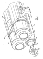
- a linear actuator system 10 is illustrated in Figure 1 .
- the system 10 includes an electromechanical actuator 12 interconnected between first and second member 14, 16.
- the actuator 12 extends and retracts to move the first and second members 14, 16 relative to one another.
- the actuator 12 includes a housing 19 providing a first end 18 connected to the first member 14.
- a second end 20 is supported by the housing 19 for translation and is connected to the second member 16.
- a motor 22 and gearbox 24 are supported on the housing 19.
- a brake 26 is also supported by the housing 19 in the example shown and is used to cooperate with the gearbox 24 during operation of the actuator 12.
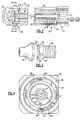
- the actuator 12 includes a sleeve 30 supporting an end portion 32 that provides the second end 20.
- the sleeve 30 is received within a bore in the housing 19 (shown in Figures 1 and 4 ) for linear translation relative to the housing 19.
- a ball screw 28 is disposed within the sleeve 30 and is rotationally driven about an axis A by the motor 22 through gearbox 24.
- One end of the ball screw 28 is supported within the housing 19 by a thrust bearing 31.
- the ball screw 28 has an outer surface providing a ball screw track supporting balls 29 received by a corresponding ball screw track on an inner diameter of the sleeve 30.
- the ball screw 28 supports a stop 34 opposite the thrust bearing 31 and adjacent to the end portion 32.
- First and second stop lugs 36, 38 are respectively provided on the stop 34 and end portion 32.
- the first and second lugs 36, 38 engage one another in a travel limiting position, which corresponds to a fully retracted position in the example shown in Figure 2 . It should be understood that a similar end of travel stop can be used for the fully extended position.
- a compliant member 40 is operatively arranged between the stop 34 and ball screw 28 to absorb energy between the ball screw and stop 28, 34 in the travel limiting position to prevent jamming and/or damage to the actuator 12.
- the compliant member 40 includes a torsion spring provided by first, second and third tubular members 42, 44, 46.
- the members 42, 44, 46 are nested relative to one another and disposed within an inner bore in the ball screw 28.
- the first member 42 is secured to the stop 34 by a pin 48 at an outer end 56 of the compliant member 40, shown in Figure 3 . Ends of the first and second members 42, 44 are secured to one another by a pin 50 at an inner end 54 opposite the stop 34.
- the second and third members 44, 46 are secured to one another by a third pin 52 at the outer end 56.
- the third member 46 is secured to the ball screw 28 by a pin 53 at the inner end 54.
- One or more of the pins 48, 50, 52, 53 may be replaced by splines, welds or bolts, for example.
- the material, length and wall thickness of first, second and third members 42, 44, 46 are selected based upon the available spaces and the operating characteristics of the actuator 12. A fewer or greater number of tubular members than the number disclosed may be used. Nesting tubular members enables a torsional spring to be provided in a very compact space.
- the travel limiting position is shown in Figure 4 in which first and second surfaces 37, 39 respectively of the first and second stop lugs 36, 38 have engaged one another after rotation R of the ball screw 28 about axis A.
- the kinetic energy of the motor 22 and gearbox 24 will continue to be transmitted to the ball screw 28.
- This kinetic energy will be transmitted from the stop 34 to the first member 42, then to the second member 44, then to the third member 46 to absorb the rotational energy.
- the first, second and third members 42, 44, 46 will unload and back-drive the ball screw 28, gearbox 24 and electric motor 22.
- the compliant member 40 When the first and second stop lugs 36, 38 initially engage one another, the compliant member 40 is unloaded. With the first and second stop lugs 36, 38 engaging one another and the compliant member unloaded 40, a gap 60 of a first size is provided between first and second faces 58, 59 of the stop 34 and ball screw 28. As the compliant member 40 becomes loaded the gap 60 will reduce to a second size as the ball screw 28 continues to rotate and the axial length of the first, second and third members 42, 44, 46 winds up. As the ball screw 28 rotates, it forces the ball screw nut to continue to translate, forcing the gap 60 to be reduced. The first size of the gap 60 is selected to prevent the first and second faces 58, 59 from engaging one another when the compliant member 40 becomes fully loaded after absorbing the inertia within the actuator 12.
Landscapes
- Engineering & Computer Science (AREA)
- General Engineering & Computer Science (AREA)
- Mechanical Engineering (AREA)
- Transmission Devices (AREA)
- Connection Of Motors, Electrical Generators, Mechanical Devices, And The Like (AREA)
Claims (8)
- Dispositif d'actionnement linéaire (12) comprenant :une première structure (28) ayant un axe (A), dans laquelle la première structure est une vis à billes (28) incluant un alésage intérieur et une surface extérieure avec une piste de vis à billes, la vis à billes ayant une première face ;une seconde structure (30) configurée pour effectuer un mouvement de translation par rapport à la première structure en réponse à la rotation de la première structure ;des première (34) et seconde (36) butées respectivement reliées de manière opérationnelle aux première et seconde structures, les première et seconde butées étant configurées pour se mettre en prise au niveau d'une position de limitation de déplacement ; etun élément élastique (40) agencé de manière opérationnelle entre les première et seconde structures et configuré pour absorber l'énergie entre les première et seconde structures dans la position de limitation de déplacement, dans lequel l'élément élastique (40) inclut un ressort de torsion, et dans lequel le ressort de torsion (40) est disposé dans l'alésage intérieur,caractérisé en ce que le ressort de torsion est réalisé par de multiples tubes imbriqués (42, 44, 46) agencés de façon coaxiale les uns par rapport aux autres autour de l'axe, et a des première et seconde parties espacées, la première partie étant reliée à la vis à billes, et
en ce que le ressort de torsion a des états chargé et déchargé ; dans lequel la première butée est reliée à la seconde partie et a une seconde face, un espacement agencé entre les première et seconde faces incluant des première et seconde dimensions respectivement dans les états déchargé et chargé, et la première dimension étant plus grande que la seconde dimension. - Dispositif d'actionnement linéaire selon la revendication 1, dans lequel la première structure est une vis à billes (28) et la seconde structure est un manchon (30) supportant la seconde butée (36).
- Dispositif d'actionnement linéaire selon la revendication 2, comprenant un logement (19) avec un alésage recevant de façon télescopique le manchon (30), la vis à billes étant agencée de façon imbriquée par rapport au manchon dans une position rétractée.
- Dispositif d'actionnement linéaire selon la revendication 3, comprenant une boîte à engrenages (24) et un moteur électrique (22) supporté par le logement, le moteur électrique étant configuré pour entraîner en rotation la vis à billes autour de l'axe par l'intermédiaire de la boîte à engrenages.
- Dispositif d'actionnement linéaire selon la revendication 2, 3 ou 4, dans lequel l'élément élastique (40) interconnecte la vis à billes (28) et la première butée (34).
- Dispositif d'actionnement linéaire selon la revendication 5, dans lequel un espacement (60) est prévu de façon axiale entre la première structure (28) et la première butée (34) dans la position de limitation de déplacement, l'espacement étant configuré pour diminuer de taille lorsque l'élément élastique absorbe l'énergie.
- Dispositif d'actionnement linéaire selon l'une quelconque des revendications précédentes, dans lequel les tubes sont interconnectés les uns aux autres, à la vis à billes et à la butée par des ergots.
- Dispositif d'actionnement linéaire selon l'une quelconque des revendications précédentes, dans lequel les tubes (42, 44, 46) sont imbriqués les uns par rapport aux autres et agencés de façon coaxiale avec la première structure (28).
Applications Claiming Priority (1)
| Application Number | Priority Date | Filing Date | Title |
|---|---|---|---|
| US12/568,759 US8109165B2 (en) | 2009-09-29 | 2009-09-29 | Compliant non-jamming end of travel stop for a ball screw actuator |
Publications (3)
| Publication Number | Publication Date |
|---|---|
| EP2302262A2 EP2302262A2 (fr) | 2011-03-30 |
| EP2302262A3 EP2302262A3 (fr) | 2011-10-26 |
| EP2302262B1 true EP2302262B1 (fr) | 2013-12-18 |
Family
ID=43384609
Family Applications (1)
| Application Number | Title | Priority Date | Filing Date |
|---|---|---|---|
| EP10251675.4A Active EP2302262B1 (fr) | 2009-09-29 | 2010-09-29 | Extrémité anti-blocage conforme de butée de déplacement pour actionneur à vis sphérique |
Country Status (7)
| Country | Link |
|---|---|
| US (1) | US8109165B2 (fr) |
| EP (1) | EP2302262B1 (fr) |
| JP (1) | JP2011078302A (fr) |
| KR (1) | KR101135813B1 (fr) |
| CN (1) | CN102032328A (fr) |
| IL (1) | IL208394A (fr) |
| ZA (1) | ZA201005847B (fr) |
Cited By (1)
| Publication number | Priority date | Publication date | Assignee | Title |
|---|---|---|---|---|
| EP2891829B1 (fr) * | 2013-10-31 | 2025-02-12 | Goodrich Corporation | Ensemble d'arrêt de position proximale d'actionneur électromécanique |
Families Citing this family (13)
| Publication number | Priority date | Publication date | Assignee | Title |
|---|---|---|---|---|
| DE102009036886A1 (de) * | 2009-08-10 | 2011-02-17 | Schaeffler Technologies Gmbh & Co. Kg | Kugelgewindetrieb mit umfangsseitigem Anschlag |
| DE102012210226A1 (de) * | 2012-06-18 | 2013-12-19 | Zf Friedrichshafen Ag | Verstellvorrichtung für ein Fahrwerk eines Fahrzeugs |
| US9182022B2 (en) * | 2012-10-17 | 2015-11-10 | Honeywell International Inc. | Ball screw actuator including a stop with an integral guide |
| US8931599B2 (en) | 2012-11-01 | 2015-01-13 | Hamilton Sundstrand Corporation | Damping end-stop of electric braking apparatus |
| US9383228B2 (en) | 2012-12-03 | 2016-07-05 | Hamilton Sundstrand Corporation | Control voltage signal synthesis system and method |
| US9103422B2 (en) * | 2013-04-11 | 2015-08-11 | Honeywell International Inc. | Ball screw actuator including a compliant ball screw stop |
| DE202013008175U1 (de) * | 2013-09-14 | 2013-10-29 | Ruia Global Fasteners Ag | Spindel |
| EP3227583B1 (fr) | 2014-12-01 | 2021-04-14 | Goodrich Actuation Systems SAS | Actionneur de stabilisateur horizontal avec caractéristiques de détection d'usure et procédé correspondant |
| FR3044635B1 (fr) | 2015-12-04 | 2018-08-17 | Ratier Figeac | Butee d'absorption d'energie de fin de course d'actionneur d'aeronef a portee destructible demontable, actionneur et aeronef |
| US20190055009A1 (en) * | 2017-08-17 | 2019-02-21 | Goodrich Corporation | Electric actuator with bidirectional compliance |
| US10663041B2 (en) | 2018-08-14 | 2020-05-26 | Hamilton Sunstrand Corporation | Jam-tolerant electric linear actuator |
| JP7700146B2 (ja) * | 2020-03-26 | 2025-06-30 | ムーグ インコーポレーテッド | 衝撃吸収アクチュエータエンドストップ |
| EP4330564B1 (fr) | 2021-04-28 | 2025-12-17 | Moog Inc. | Butée d'extrémité d'actionneur déformable en torsion |
Family Cites Families (21)
| Publication number | Priority date | Publication date | Assignee | Title |
|---|---|---|---|---|
| GB552485A (en) | 1942-01-01 | 1943-04-09 | Scophony Ltd | Improvements in releasable mechanical coupling means for rotary driving mechanism |
| US3203257A (en) * | 1962-02-23 | 1965-08-31 | Gen Motors Corp | Escapement controlled actuator |
| US3213701A (en) * | 1963-08-01 | 1965-10-26 | Garrett Corp | Linear actuator |
| US3766798A (en) * | 1972-10-04 | 1973-10-23 | United Aircraft Corp | Ball-screw actuator with stop mechanism |
| FR2567979B1 (fr) * | 1984-07-18 | 1986-12-19 | Somfy | Actionneur lineaire a systeme vis-ecrou |
| US4753572A (en) * | 1986-10-02 | 1988-06-28 | United Technologies Corporation | Propeller pitch change actuation system |
| US5451141A (en) * | 1993-12-23 | 1995-09-19 | United Technologies Corporation | Propeller pitch change machanism with inductive brake and motor |
| US5462410A (en) * | 1994-11-10 | 1995-10-31 | United Technologies Corporation | Damper and seal for propeller quill shaft |
| US5868032A (en) * | 1996-04-04 | 1999-02-09 | Thomson Saginaw Ball Screw Company, Llc | Ball screw and nut linear actuator assemblies and methods of cushioning their travel |
| JP3422632B2 (ja) * | 1996-04-05 | 2003-06-30 | 三菱重工業株式会社 | 電動アクチュエータの緩衝装置 |
| JPH10321088A (ja) * | 1997-05-22 | 1998-12-04 | Mitsubishi Electric Corp | 開閉器の操作装置 |
| US5984068A (en) * | 1997-12-01 | 1999-11-16 | Chrysler Corporation | Electro-mechanical clutch actuator |
| US6202803B1 (en) * | 1998-12-22 | 2001-03-20 | Hamilton Sundstrand Corporation | Output load limiter |
| ITTO20011138A1 (it) * | 2001-12-07 | 2003-06-09 | Skf Ind Spa | Modulo attuatore a vite. |
| JP4555083B2 (ja) * | 2002-08-13 | 2010-09-29 | コンティネンタル・テーベス・アクチエンゲゼルシヤフト・ウント・コンパニー・オッフェネ・ハンデルスゲゼルシヤフト | 電気機械式駐車ブレーキを操作する方法 |
| US7100870B2 (en) * | 2003-10-15 | 2006-09-05 | Parker-Hannifin Corporation | Jam tolerant electromechanical actuation systems and methods of operation |
| US7367891B2 (en) * | 2004-11-23 | 2008-05-06 | Hr Textron, Inc. | Techniques for controlling transfer of torque using detent members responsive to radial force |
| CN100404913C (zh) * | 2005-02-18 | 2008-07-23 | 徐众 | 自限位直线致动器 |
| JP2007187279A (ja) | 2006-01-16 | 2007-07-26 | Mitsuba Corp | リニアアクチュエータ |
| US8336818B2 (en) * | 2007-10-30 | 2012-12-25 | Parker-Hannifin Corporation | Jam tolerant electromechanical actuation systems and methods of operation |
| US8281678B2 (en) * | 2008-12-30 | 2012-10-09 | Eaton Corporation | Ballscrew assembly with detection feature |
-
2009
- 2009-09-29 US US12/568,759 patent/US8109165B2/en active Active
-
2010
- 2010-08-16 ZA ZA2010/05847A patent/ZA201005847B/en unknown
- 2010-09-07 KR KR1020100087216A patent/KR101135813B1/ko not_active Expired - Fee Related
- 2010-09-14 JP JP2010205241A patent/JP2011078302A/ja active Pending
- 2010-09-29 EP EP10251675.4A patent/EP2302262B1/fr active Active
- 2010-09-29 CN CN2010102984825A patent/CN102032328A/zh active Pending
- 2010-10-03 IL IL208394A patent/IL208394A/en not_active IP Right Cessation
Cited By (1)
| Publication number | Priority date | Publication date | Assignee | Title |
|---|---|---|---|---|
| EP2891829B1 (fr) * | 2013-10-31 | 2025-02-12 | Goodrich Corporation | Ensemble d'arrêt de position proximale d'actionneur électromécanique |
Also Published As
| Publication number | Publication date |
|---|---|
| KR101135813B1 (ko) | 2012-04-16 |
| IL208394A (en) | 2013-08-29 |
| KR20110035880A (ko) | 2011-04-06 |
| CN102032328A (zh) | 2011-04-27 |
| JP2011078302A (ja) | 2011-04-14 |
| US8109165B2 (en) | 2012-02-07 |
| IL208394A0 (en) | 2011-02-28 |
| ZA201005847B (en) | 2011-04-28 |
| US20110072921A1 (en) | 2011-03-31 |
| EP2302262A2 (fr) | 2011-03-30 |
| EP2302262A3 (fr) | 2011-10-26 |
Similar Documents
| Publication | Publication Date | Title |
|---|---|---|
| EP2302262B1 (fr) | Extrémité anti-blocage conforme de butée de déplacement pour actionneur à vis sphérique | |
| JP6078311B2 (ja) | 自動的にロックするリニアアクチュエータ | |
| EP1165985B1 (fr) | Dispositif de commande a demultiplication compacte | |
| EP2969706B1 (fr) | Ensemble de direction à assistance électrique | |
| JP6000527B2 (ja) | 電動アクチュエータ、電動アクチュエータ動力切断方法、及び電動アクチュエータ動力切断装置 | |
| EP1955947A2 (fr) | Actionneur | |
| EP1548327A1 (fr) | Actionneur linéaire | |
| EP2566734B1 (fr) | Cylindre de frein à accumulateur présentant un moteur électrique monté à l'intérieur du ressort accumulateur | |
| EP3204677B1 (fr) | Actionneur pour actionner un dispositif de vanne | |
| CN108780986A (zh) | 蛇形机器人 | |
| EP4330564B1 (fr) | Butée d'extrémité d'actionneur déformable en torsion | |
| DE10214670B4 (de) | Bremszuspanneinrichtung mit elektrisch betätigtem Verschleißnachsteller | |
| EP2916043A2 (fr) | Actionneur linéaire à vis comprenant une tige de torsion avec butée bidirectionnelle | |
| JP2012072867A (ja) | サスペンション装置及びこのサスペンション装置を組み込んだ車両 | |
| DE10214672B4 (de) | Bremszuspanneinrichtung mit elektrisch betätigter Einrichtung zum Not- und Hilfslösen | |
| DE10214671B4 (de) | Bremszuspanneinrichtung mit elektrisch betätigter Verschleißnachstell- und Not- und Hilfslöseeinrichtung | |
| CN116730245B (zh) | 丝杠组件、线性致动装置和升降设备 | |
| EP2492533B1 (fr) | Ensemble formant vis sphérique | |
| US12281691B2 (en) | Shock absorbing actuator end stop | |
| EP3611374A1 (fr) | Actionneur rotatif | |
| CN107701606A (zh) | 双卷簧、旋转装置和待促动的系统 | |
| WO2005015044A1 (fr) | Freins |
Legal Events
| Date | Code | Title | Description |
|---|---|---|---|
| PUAI | Public reference made under article 153(3) epc to a published international application that has entered the european phase |
Free format text: ORIGINAL CODE: 0009012 |
|
| AK | Designated contracting states |
Kind code of ref document: A2 Designated state(s): AL AT BE BG CH CY CZ DE DK EE ES FI FR GB GR HR HU IE IS IT LI LT LU LV MC MK MT NL NO PL PT RO SE SI SK SM TR |
|
| AX | Request for extension of the european patent |
Extension state: BA ME RS |
|
| PUAL | Search report despatched |
Free format text: ORIGINAL CODE: 0009013 |
|
| AK | Designated contracting states |
Kind code of ref document: A3 Designated state(s): AL AT BE BG CH CY CZ DE DK EE ES FI FR GB GR HR HU IE IS IT LI LT LU LV MC MK MT NL NO PL PT RO SE SI SK SM TR |
|
| AX | Request for extension of the european patent |
Extension state: BA ME RS |
|
| RIC1 | Information provided on ipc code assigned before grant |
Ipc: F16H 25/20 20060101AFI20110919BHEP |
|
| 17P | Request for examination filed |
Effective date: 20120426 |
|
| 17Q | First examination report despatched |
Effective date: 20120620 |
|
| REG | Reference to a national code |
Ref country code: DE Ref legal event code: R079 Ref document number: 602010012495 Country of ref document: DE Free format text: PREVIOUS MAIN CLASS: F16H0025200000 Ipc: F16H0025220000 |
|
| RIC1 | Information provided on ipc code assigned before grant |
Ipc: F16H 25/20 20060101ALI20130614BHEP Ipc: F16H 25/22 20060101AFI20130614BHEP |
|
| GRAP | Despatch of communication of intention to grant a patent |
Free format text: ORIGINAL CODE: EPIDOSNIGR1 |
|
| INTG | Intention to grant announced |
Effective date: 20130802 |
|
| GRAS | Grant fee paid |
Free format text: ORIGINAL CODE: EPIDOSNIGR3 |
|
| GRAA | (expected) grant |
Free format text: ORIGINAL CODE: 0009210 |
|
| AK | Designated contracting states |
Kind code of ref document: B1 Designated state(s): AL AT BE BG CH CY CZ DE DK EE ES FI FR GB GR HR HU IE IS IT LI LT LU LV MC MK MT NL NO PL PT RO SE SI SK SM TR |
|
| REG | Reference to a national code |
Ref country code: GB Ref legal event code: FG4D |
|
| REG | Reference to a national code |
Ref country code: CH Ref legal event code: EP |
|
| REG | Reference to a national code |
Ref country code: AT Ref legal event code: REF Ref document number: 645790 Country of ref document: AT Kind code of ref document: T Effective date: 20140115 |
|
| REG | Reference to a national code |
Ref country code: IE Ref legal event code: FG4D |
|
| REG | Reference to a national code |
Ref country code: DE Ref legal event code: R096 Ref document number: 602010012495 Country of ref document: DE Effective date: 20140213 |
|
| REG | Reference to a national code |
Ref country code: NL Ref legal event code: VDEP Effective date: 20131218 |
|
| PG25 | Lapsed in a contracting state [announced via postgrant information from national office to epo] |
Ref country code: SE Free format text: LAPSE BECAUSE OF FAILURE TO SUBMIT A TRANSLATION OF THE DESCRIPTION OR TO PAY THE FEE WITHIN THE PRESCRIBED TIME-LIMIT Effective date: 20131218 Ref country code: NO Free format text: LAPSE BECAUSE OF FAILURE TO SUBMIT A TRANSLATION OF THE DESCRIPTION OR TO PAY THE FEE WITHIN THE PRESCRIBED TIME-LIMIT Effective date: 20140318 Ref country code: LT Free format text: LAPSE BECAUSE OF FAILURE TO SUBMIT A TRANSLATION OF THE DESCRIPTION OR TO PAY THE FEE WITHIN THE PRESCRIBED TIME-LIMIT Effective date: 20131218 Ref country code: HR Free format text: LAPSE BECAUSE OF FAILURE TO SUBMIT A TRANSLATION OF THE DESCRIPTION OR TO PAY THE FEE WITHIN THE PRESCRIBED TIME-LIMIT Effective date: 20131218 Ref country code: FI Free format text: LAPSE BECAUSE OF FAILURE TO SUBMIT A TRANSLATION OF THE DESCRIPTION OR TO PAY THE FEE WITHIN THE PRESCRIBED TIME-LIMIT Effective date: 20131218 |
|
| REG | Reference to a national code |
Ref country code: AT Ref legal event code: MK05 Ref document number: 645790 Country of ref document: AT Kind code of ref document: T Effective date: 20131218 |
|
| REG | Reference to a national code |
Ref country code: LT Ref legal event code: MG4D |
|
| PG25 | Lapsed in a contracting state [announced via postgrant information from national office to epo] |
Ref country code: LV Free format text: LAPSE BECAUSE OF FAILURE TO SUBMIT A TRANSLATION OF THE DESCRIPTION OR TO PAY THE FEE WITHIN THE PRESCRIBED TIME-LIMIT Effective date: 20131218 |
|
| PG25 | Lapsed in a contracting state [announced via postgrant information from national office to epo] |
Ref country code: IS Free format text: LAPSE BECAUSE OF FAILURE TO SUBMIT A TRANSLATION OF THE DESCRIPTION OR TO PAY THE FEE WITHIN THE PRESCRIBED TIME-LIMIT Effective date: 20140418 Ref country code: EE Free format text: LAPSE BECAUSE OF FAILURE TO SUBMIT A TRANSLATION OF THE DESCRIPTION OR TO PAY THE FEE WITHIN THE PRESCRIBED TIME-LIMIT Effective date: 20131218 Ref country code: BE Free format text: LAPSE BECAUSE OF FAILURE TO SUBMIT A TRANSLATION OF THE DESCRIPTION OR TO PAY THE FEE WITHIN THE PRESCRIBED TIME-LIMIT Effective date: 20131218 |
|
| PG25 | Lapsed in a contracting state [announced via postgrant information from national office to epo] |
Ref country code: RO Free format text: LAPSE BECAUSE OF FAILURE TO SUBMIT A TRANSLATION OF THE DESCRIPTION OR TO PAY THE FEE WITHIN THE PRESCRIBED TIME-LIMIT Effective date: 20131218 Ref country code: SK Free format text: LAPSE BECAUSE OF FAILURE TO SUBMIT A TRANSLATION OF THE DESCRIPTION OR TO PAY THE FEE WITHIN THE PRESCRIBED TIME-LIMIT Effective date: 20131218 Ref country code: AT Free format text: LAPSE BECAUSE OF FAILURE TO SUBMIT A TRANSLATION OF THE DESCRIPTION OR TO PAY THE FEE WITHIN THE PRESCRIBED TIME-LIMIT Effective date: 20131218 Ref country code: PT Free format text: LAPSE BECAUSE OF FAILURE TO SUBMIT A TRANSLATION OF THE DESCRIPTION OR TO PAY THE FEE WITHIN THE PRESCRIBED TIME-LIMIT Effective date: 20140418 Ref country code: ES Free format text: LAPSE BECAUSE OF FAILURE TO SUBMIT A TRANSLATION OF THE DESCRIPTION OR TO PAY THE FEE WITHIN THE PRESCRIBED TIME-LIMIT Effective date: 20131218 Ref country code: CZ Free format text: LAPSE BECAUSE OF FAILURE TO SUBMIT A TRANSLATION OF THE DESCRIPTION OR TO PAY THE FEE WITHIN THE PRESCRIBED TIME-LIMIT Effective date: 20131218 Ref country code: CY Free format text: LAPSE BECAUSE OF FAILURE TO SUBMIT A TRANSLATION OF THE DESCRIPTION OR TO PAY THE FEE WITHIN THE PRESCRIBED TIME-LIMIT Effective date: 20131218 Ref country code: PL Free format text: LAPSE BECAUSE OF FAILURE TO SUBMIT A TRANSLATION OF THE DESCRIPTION OR TO PAY THE FEE WITHIN THE PRESCRIBED TIME-LIMIT Effective date: 20131218 Ref country code: NL Free format text: LAPSE BECAUSE OF FAILURE TO SUBMIT A TRANSLATION OF THE DESCRIPTION OR TO PAY THE FEE WITHIN THE PRESCRIBED TIME-LIMIT Effective date: 20131218 |
|
| REG | Reference to a national code |
Ref country code: DE Ref legal event code: R097 Ref document number: 602010012495 Country of ref document: DE |
|
| PLBE | No opposition filed within time limit |
Free format text: ORIGINAL CODE: 0009261 |
|
| STAA | Information on the status of an ep patent application or granted ep patent |
Free format text: STATUS: NO OPPOSITION FILED WITHIN TIME LIMIT |
|
| PG25 | Lapsed in a contracting state [announced via postgrant information from national office to epo] |
Ref country code: DK Free format text: LAPSE BECAUSE OF FAILURE TO SUBMIT A TRANSLATION OF THE DESCRIPTION OR TO PAY THE FEE WITHIN THE PRESCRIBED TIME-LIMIT Effective date: 20131218 |
|
| 26N | No opposition filed |
Effective date: 20140919 |
|
| REG | Reference to a national code |
Ref country code: DE Ref legal event code: R097 Ref document number: 602010012495 Country of ref document: DE Effective date: 20140919 |
|
| PG25 | Lapsed in a contracting state [announced via postgrant information from national office to epo] |
Ref country code: LU Free format text: LAPSE BECAUSE OF FAILURE TO SUBMIT A TRANSLATION OF THE DESCRIPTION OR TO PAY THE FEE WITHIN THE PRESCRIBED TIME-LIMIT Effective date: 20140929 Ref country code: MC Free format text: LAPSE BECAUSE OF FAILURE TO SUBMIT A TRANSLATION OF THE DESCRIPTION OR TO PAY THE FEE WITHIN THE PRESCRIBED TIME-LIMIT Effective date: 20131218 |
|
| REG | Reference to a national code |
Ref country code: CH Ref legal event code: PL |
|
| PG25 | Lapsed in a contracting state [announced via postgrant information from national office to epo] |
Ref country code: SI Free format text: LAPSE BECAUSE OF FAILURE TO SUBMIT A TRANSLATION OF THE DESCRIPTION OR TO PAY THE FEE WITHIN THE PRESCRIBED TIME-LIMIT Effective date: 20131218 |
|
| REG | Reference to a national code |
Ref country code: IE Ref legal event code: MM4A |
|
| PG25 | Lapsed in a contracting state [announced via postgrant information from national office to epo] |
Ref country code: CH Free format text: LAPSE BECAUSE OF NON-PAYMENT OF DUE FEES Effective date: 20140930 Ref country code: LI Free format text: LAPSE BECAUSE OF NON-PAYMENT OF DUE FEES Effective date: 20140930 |
|
| PG25 | Lapsed in a contracting state [announced via postgrant information from national office to epo] |
Ref country code: IE Free format text: LAPSE BECAUSE OF NON-PAYMENT OF DUE FEES Effective date: 20140929 |
|
| PG25 | Lapsed in a contracting state [announced via postgrant information from national office to epo] |
Ref country code: SM Free format text: LAPSE BECAUSE OF FAILURE TO SUBMIT A TRANSLATION OF THE DESCRIPTION OR TO PAY THE FEE WITHIN THE PRESCRIBED TIME-LIMIT Effective date: 20131218 |
|
| PG25 | Lapsed in a contracting state [announced via postgrant information from national office to epo] |
Ref country code: MT Free format text: LAPSE BECAUSE OF FAILURE TO SUBMIT A TRANSLATION OF THE DESCRIPTION OR TO PAY THE FEE WITHIN THE PRESCRIBED TIME-LIMIT Effective date: 20131218 Ref country code: GR Free format text: LAPSE BECAUSE OF FAILURE TO SUBMIT A TRANSLATION OF THE DESCRIPTION OR TO PAY THE FEE WITHIN THE PRESCRIBED TIME-LIMIT Effective date: 20140319 Ref country code: IT Free format text: LAPSE BECAUSE OF FAILURE TO SUBMIT A TRANSLATION OF THE DESCRIPTION OR TO PAY THE FEE WITHIN THE PRESCRIBED TIME-LIMIT Effective date: 20131218 Ref country code: BG Free format text: LAPSE BECAUSE OF FAILURE TO SUBMIT A TRANSLATION OF THE DESCRIPTION OR TO PAY THE FEE WITHIN THE PRESCRIBED TIME-LIMIT Effective date: 20131218 |
|
| PG25 | Lapsed in a contracting state [announced via postgrant information from national office to epo] |
Ref country code: HU Free format text: LAPSE BECAUSE OF FAILURE TO SUBMIT A TRANSLATION OF THE DESCRIPTION OR TO PAY THE FEE WITHIN THE PRESCRIBED TIME-LIMIT; INVALID AB INITIO Effective date: 20100929 Ref country code: TR Free format text: LAPSE BECAUSE OF FAILURE TO SUBMIT A TRANSLATION OF THE DESCRIPTION OR TO PAY THE FEE WITHIN THE PRESCRIBED TIME-LIMIT Effective date: 20131218 |
|
| REG | Reference to a national code |
Ref country code: FR Ref legal event code: PLFP Year of fee payment: 7 |
|
| REG | Reference to a national code |
Ref country code: DE Ref legal event code: R082 Ref document number: 602010012495 Country of ref document: DE Representative=s name: SCHMITT-NILSON SCHRAUD WAIBEL WOHLFROM PATENTA, DE |
|
| REG | Reference to a national code |
Ref country code: FR Ref legal event code: PLFP Year of fee payment: 8 |
|
| PG25 | Lapsed in a contracting state [announced via postgrant information from national office to epo] |
Ref country code: MK Free format text: LAPSE BECAUSE OF FAILURE TO SUBMIT A TRANSLATION OF THE DESCRIPTION OR TO PAY THE FEE WITHIN THE PRESCRIBED TIME-LIMIT Effective date: 20131218 |
|
| REG | Reference to a national code |
Ref country code: FR Ref legal event code: PLFP Year of fee payment: 9 |
|
| PG25 | Lapsed in a contracting state [announced via postgrant information from national office to epo] |
Ref country code: AL Free format text: LAPSE BECAUSE OF FAILURE TO SUBMIT A TRANSLATION OF THE DESCRIPTION OR TO PAY THE FEE WITHIN THE PRESCRIBED TIME-LIMIT Effective date: 20131218 |
|
| P01 | Opt-out of the competence of the unified patent court (upc) registered |
Effective date: 20230522 |
|
| PGFP | Annual fee paid to national office [announced via postgrant information from national office to epo] |
Ref country code: DE Payment date: 20250820 Year of fee payment: 16 |
|
| PGFP | Annual fee paid to national office [announced via postgrant information from national office to epo] |
Ref country code: GB Payment date: 20250822 Year of fee payment: 16 |
|
| PGFP | Annual fee paid to national office [announced via postgrant information from national office to epo] |
Ref country code: FR Payment date: 20250820 Year of fee payment: 16 |