EP2302334A1 - Partie supérieure d'un débitmètre, débitmètre et procédé de fabrication d'une partie supérieure d'un débitmètre - Google Patents
Partie supérieure d'un débitmètre, débitmètre et procédé de fabrication d'une partie supérieure d'un débitmètre Download PDFInfo
- Publication number
- EP2302334A1 EP2302334A1 EP10010984A EP10010984A EP2302334A1 EP 2302334 A1 EP2302334 A1 EP 2302334A1 EP 10010984 A EP10010984 A EP 10010984A EP 10010984 A EP10010984 A EP 10010984A EP 2302334 A1 EP2302334 A1 EP 2302334A1
- Authority
- EP
- European Patent Office
- Prior art keywords
- insulating body
- flow meter
- main body
- spraying
- insulating
- Prior art date
- Legal status (The legal status is an assumption and is not a legal conclusion. Google has not performed a legal analysis and makes no representation as to the accuracy of the status listed.)
- Withdrawn
Links
- 238000004519 manufacturing process Methods 0.000 title claims abstract description 14
- 238000000034 method Methods 0.000 claims abstract description 19
- 239000004033 plastic Substances 0.000 claims abstract description 14
- 229920003023 plastic Polymers 0.000 claims abstract description 14
- 238000002347 injection Methods 0.000 claims abstract description 4
- 239000007924 injection Substances 0.000 claims abstract description 4
- 238000009413 insulation Methods 0.000 claims description 23
- 230000001066 destructive effect Effects 0.000 claims description 13
- 238000005507 spraying Methods 0.000 claims description 10
- 238000001746 injection moulding Methods 0.000 claims description 8
- 238000003780 insertion Methods 0.000 claims description 7
- 230000037431 insertion Effects 0.000 claims description 7
- 238000002955 isolation Methods 0.000 abstract 4
- 239000007788 liquid Substances 0.000 description 10
- 238000011161 development Methods 0.000 description 4
- 230000018109 developmental process Effects 0.000 description 4
- 230000006378 damage Effects 0.000 description 3
- 235000013361 beverage Nutrition 0.000 description 2
- XLYOFNOQVPJJNP-UHFFFAOYSA-N water Substances O XLYOFNOQVPJJNP-UHFFFAOYSA-N 0.000 description 2
- 235000013405 beer Nutrition 0.000 description 1
- 150000001875 compounds Chemical class 0.000 description 1
- 238000005520 cutting process Methods 0.000 description 1
- 230000001419 dependent effect Effects 0.000 description 1
- 238000010292 electrical insulation Methods 0.000 description 1
- 239000003292 glue Substances 0.000 description 1
- 229910052500 inorganic mineral Inorganic materials 0.000 description 1
- 238000012423 maintenance Methods 0.000 description 1
- 239000000463 material Substances 0.000 description 1
- 239000011707 mineral Substances 0.000 description 1
- 238000002360 preparation method Methods 0.000 description 1
- 239000000126 substance Substances 0.000 description 1
- 238000002604 ultrasonography Methods 0.000 description 1
- 238000005406 washing Methods 0.000 description 1
- 238000003466 welding Methods 0.000 description 1
Images


Classifications
-
- G—PHYSICS
- G01—MEASURING; TESTING
- G01F—MEASURING VOLUME, VOLUME FLOW, MASS FLOW OR LIQUID LEVEL; METERING BY VOLUME
- G01F1/00—Measuring the volume flow or mass flow of fluid or fluent solid material wherein the fluid passes through a meter in a continuous flow
- G01F1/05—Measuring the volume flow or mass flow of fluid or fluent solid material wherein the fluid passes through a meter in a continuous flow by using mechanical effects
- G01F1/06—Measuring the volume flow or mass flow of fluid or fluent solid material wherein the fluid passes through a meter in a continuous flow by using mechanical effects using rotating vanes with tangential admission
- G01F1/075—Measuring the volume flow or mass flow of fluid or fluent solid material wherein the fluid passes through a meter in a continuous flow by using mechanical effects using rotating vanes with tangential admission with magnetic or electromagnetic coupling to the indicating device
-
- G—PHYSICS
- G01—MEASURING; TESTING
- G01F—MEASURING VOLUME, VOLUME FLOW, MASS FLOW OR LIQUID LEVEL; METERING BY VOLUME
- G01F15/00—Details of, or accessories for, apparatus of groups G01F1/00 - G01F13/00 insofar as such details or appliances are not adapted to particular types of such apparatus
- G01F15/14—Casings, e.g. of special material
Definitions
- the object of the invention is to propose a flow meter, a top part for a flowmeter or a method for producing a top part for a flow meter, which allow increased safety and in which the production can be improved.
- a double insulation is likewise created between live components and the liquid-carrying space of the flow meter. Furthermore, it can be prevented that a hairline, for example, in the second insulating body continues in the first insulating body and thus, for example, a short circuit or dangerous situation for the user arises.
- damage to the main body which affects either only the first or the second insulating body, does not immediately destroy the complete electrical insulation. As a result, the security can be increased significantly, while the probability of failure can be reduced. Furthermore, this can also the lifetime of such Increase flow meter or a corresponding upper part for a flow meter.
- a particularly secure mounting of the first insulating body in the second insulating body is given when at least two with respect to the first insulating body mutually opposite tongue and groove joints are formed.
- two opposing undercuts with respect to the first insulating body may also be present. This prevents, for example, that the first insulating body can be removed by tilting possibly from the second insulating body. Analogously, this also applies to a non-destructive insertion.
- the Cover part with the main body in particular be welded by ultrasound.
- the cover part is welded, for example, only with the first insulating body.
- a welding is characterized in particular by the fact that such a compound also offers a very good insulation in terms of liquids.
- a flowmeter according to the invention is characterized in that an upper part according to the invention or an embodiment or development of an upper part according to the invention is present.
- Upper and lower part of the flow meter limit for example, the liquid-carrying space. Possibly. can be arranged here, for example, an impeller, which moves in the liquid flow and whose number of revolutions can be measured, for example, to determine the volume flowed through.
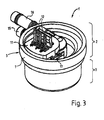
- FIG. 1 shows a schematic section through a flow meter 1 with an upper part 2 and a lower part 3.
- Upper and lower part 2, 3 surround the liquid-carrying space 4.
- the upper part 2 comprises a main body 5.
- the main body 5 in turn is composed of two insulating bodies, a first insulating body 6 and a second insulating body 7.
- the main body with the two insulating bodies is produced in a so-called two-component process.
- Such a production process is a plastic injection molding process in which only a single tool is required to produce the main body. Two different plastics (two components) are injected into this injection molding tool.
- the second insulating body 6 is undercut by the first insulating body 7.
- a circumferential edge 8 is present, which engages in the sense of a tongue and groove connection in a groove 9 of the second insulating body 7. It is therefore no longer possible to remove the first insulating body 6 from the second insulating body 7 in a non-destructive manner. If one were to try to isolate the first insulation body from another flow meter, for example by destroying the corresponding second insulation body, without destroying it, it would no longer be possible for this first insulation body to no longer be present in a corresponding second insulation body, the first insulation body includes pushing in without destroying at least one of them.
- the first insulating body 6 also serves to receive a Hall sensor 10.
- a cover part 11 is placed and welded (ultrasonically welded). Through the cover 11 corresponding pins for electrical contacting 12 of the Hall sensor 10 are performed.
Landscapes
- Physics & Mathematics (AREA)
- Fluid Mechanics (AREA)
- General Physics & Mathematics (AREA)
- Electromagnetism (AREA)
- Measuring Volume Flow (AREA)
Applications Claiming Priority (1)
| Application Number | Priority Date | Filing Date | Title |
|---|---|---|---|
| DE200910043344 DE102009043344A1 (de) | 2009-09-29 | 2009-09-29 | Oberteil für einen Durchflussmesser, Durchflussmesser sowie Verfahren zur Herstellung eines Oberteils für einen Durchflussmesser |
Publications (1)
| Publication Number | Publication Date |
|---|---|
| EP2302334A1 true EP2302334A1 (fr) | 2011-03-30 |
Family
ID=43447777
Family Applications (1)
| Application Number | Title | Priority Date | Filing Date |
|---|---|---|---|
| EP10010984A Withdrawn EP2302334A1 (fr) | 2009-09-29 | 2010-09-28 | Partie supérieure d'un débitmètre, débitmètre et procédé de fabrication d'une partie supérieure d'un débitmètre |
Country Status (2)
| Country | Link |
|---|---|
| EP (1) | EP2302334A1 (fr) |
| DE (1) | DE102009043344A1 (fr) |
Cited By (1)
| Publication number | Priority date | Publication date | Assignee | Title |
|---|---|---|---|---|
| EP3035005A1 (fr) * | 2014-12-18 | 2016-06-22 | BSH Hausgeräte GmbH | Ensemble rotorique, debitmetre, rotor et appareil transportant de l'eau |
Citations (1)
| Publication number | Priority date | Publication date | Assignee | Title |
|---|---|---|---|---|
| EP2056075A2 (fr) | 2007-11-05 | 2009-05-06 | Digmesa Ag | Partie supérieure pour un débitmètre et débitmètre |
-
2009
- 2009-09-29 DE DE200910043344 patent/DE102009043344A1/de not_active Withdrawn
-
2010
- 2010-09-28 EP EP10010984A patent/EP2302334A1/fr not_active Withdrawn
Patent Citations (1)
| Publication number | Priority date | Publication date | Assignee | Title |
|---|---|---|---|---|
| EP2056075A2 (fr) | 2007-11-05 | 2009-05-06 | Digmesa Ag | Partie supérieure pour un débitmètre et débitmètre |
Non-Patent Citations (3)
| Title |
|---|
| A. MANNSCHATZ, T. MORITZ: "Keramik-Keramik-Werkstoffverbunde über 2-Komponenten-Spritzgiessen", 31 December 2008 (2008-12-31), pages 26 - 26, XP002617836, Retrieved from the Internet <URL:http://www.keramikspritzguss.eu/upload/pdf/TechInfo/IKTS/Keramik-Keramik-Verbund_d.pdf> [retrieved on 20110121] * |
| E. SCHMACHTENBERG: "Mehrkomponentenspritzgiessen", 30 September 2006 (2006-09-30), XP002617843, Retrieved from the Internet <URL:http://www.lkt.uni-erlangen.de/forschung/bereiche/thermoplastverarbeitung/Infoblatt_Mehrkomponenten_SG.pdf> [retrieved on 20110121] * |
| W. EBERHARDT, M. ASHAUER, P. SCHILLING, M. MÜNCH, R. BRIEGEL: "Flexibles modulares Verfahren für die Entwicklung von Kunststoff-Miniaturgehäusen für eine Familie von Durchflusssensoren", 31 May 2002 (2002-05-31), XP002617844, Retrieved from the Internet <URL:http://www.imat.hsg-imit.de/fileadmin/hsg-imat/pdfs/aif12416.pdf> [retrieved on 20110121] * |
Cited By (1)
| Publication number | Priority date | Publication date | Assignee | Title |
|---|---|---|---|---|
| EP3035005A1 (fr) * | 2014-12-18 | 2016-06-22 | BSH Hausgeräte GmbH | Ensemble rotorique, debitmetre, rotor et appareil transportant de l'eau |
Also Published As
| Publication number | Publication date |
|---|---|
| DE102009043344A1 (de) | 2011-03-31 |
Similar Documents
| Publication | Publication Date | Title |
|---|---|---|
| EP2269011B1 (fr) | Système de mesure ultrasonore | |
| EP2547415B1 (fr) | Dispositif filtrant | |
| DE10320145B4 (de) | Magnetische Detektionsvorrichtung | |
| EP2021809B1 (fr) | Capteur inductif | |
| EP3362801B1 (fr) | Module de détection pour un capteur de courant, et procédé de montage d'un module de détection | |
| DE102007034099B4 (de) | Vorrichtung zur berührungslosen Erfassung von Relativpositionen zweier zueinander bewegbarer Teile | |
| EP2700912B1 (fr) | Appareil de mesure de débit à induction magnétique et son procédé de fabrication | |
| DE10013218A1 (de) | Verfahren zur Herstellung eines Positionssensors und Positionssensor | |
| DE102007038895A1 (de) | Durchflussmessgerät | |
| EP3000156B1 (fr) | Dispositif servant à établir un contact électrique entre un circuit imprimé et un moteur électrique | |
| EP2302334A1 (fr) | Partie supérieure d'un débitmètre, débitmètre et procédé de fabrication d'une partie supérieure d'un débitmètre | |
| DE102014013356A1 (de) | Träger für ein Sensorelement, Bauteilgruppe und Drehzahlsensor | |
| EP4094642B1 (fr) | Distributeur automatique de boissons | |
| DE10256709A1 (de) | Haltestruktur für eine elektronische Komponente und Verfahren zum Halten der elektronischen Komponente | |
| WO2020207827A1 (fr) | Adaptateur tubulaire hygiénique | |
| WO2014173387A1 (fr) | Micromoteurs pour serrures d'automobile munies d'une butée axiale pour l'axe de moteur | |
| EP4392750A1 (fr) | Appareil de capteur pour un système de direction de véhicule à moteur, système de direction pour un véhicule à moteur et procédé de production d'un appareil de capteur | |
| WO2016037676A1 (fr) | Support pour élément capteur, groupe d'éléments et capteur de vitesse de rotation | |
| WO2023025380A1 (fr) | Dispositif de capteur pour un système de direction de véhicule automobile, système de direction pour un véhicule automobile et procédé de fabrication d'un dispositif de capteur | |
| WO2021004691A1 (fr) | Dispositif d'avertissement à fabrication variable pour la surveillance d'un niveau de remplissage de contenant, outil de moulage par injection et procédé de fabrication | |
| EP2031356B1 (fr) | Capteur | |
| DE102008006263A1 (de) | Durchflussmesser für die Flüssigkeitsleitung in flüssigkeitsführenden Haushaltsmaschinen | |
| EP2944926B1 (fr) | Débitmètre de liquide | |
| DE102014210296A1 (de) | Vorrichtung und Verfahren zum Faserspritzgießen von Spritzgussteilen | |
| DE102008040072A1 (de) | Verfahren zur Herstellung einer Sensorvorrichtung sowie Sensorvorrichtung |
Legal Events
| Date | Code | Title | Description |
|---|---|---|---|
| PUAI | Public reference made under article 153(3) epc to a published international application that has entered the european phase |
Free format text: ORIGINAL CODE: 0009012 |
|
| AK | Designated contracting states |
Kind code of ref document: A1 Designated state(s): AL AT BE BG CH CY CZ DE DK EE ES FI FR GB GR HR HU IE IS IT LI LT LU LV MC MK MT NL NO PL PT RO SE SI SK SM TR |
|
| AX | Request for extension of the european patent |
Extension state: BA ME RS |
|
| STAA | Information on the status of an ep patent application or granted ep patent |
Free format text: STATUS: THE APPLICATION IS DEEMED TO BE WITHDRAWN |
|
| 18D | Application deemed to be withdrawn |
Effective date: 20111001 |