EP2302719A1 - Agent de liaison - Google Patents
Agent de liaison Download PDFInfo
- Publication number
- EP2302719A1 EP2302719A1 EP10251326A EP10251326A EP2302719A1 EP 2302719 A1 EP2302719 A1 EP 2302719A1 EP 10251326 A EP10251326 A EP 10251326A EP 10251326 A EP10251326 A EP 10251326A EP 2302719 A1 EP2302719 A1 EP 2302719A1
- Authority
- EP
- European Patent Office
- Prior art keywords
- bonding agent
- fuel
- solid electrolyte
- agent according
- conductive connection
- Prior art date
- Legal status (The legal status is an assumption and is not a legal conclusion. Google has not performed a legal analysis and makes no representation as to the accuracy of the status listed.)
- Granted
Links
Images





Classifications
-
- H—ELECTRICITY
- H01—ELECTRIC ELEMENTS
- H01M—PROCESSES OR MEANS, e.g. BATTERIES, FOR THE DIRECT CONVERSION OF CHEMICAL ENERGY INTO ELECTRICAL ENERGY
- H01M8/00—Fuel cells; Manufacture thereof
- H01M8/02—Details
- H01M8/0271—Sealing or supporting means around electrodes, matrices or membranes
- H01M8/028—Sealing means characterised by their material
- H01M8/0282—Inorganic material
-
- H—ELECTRICITY
- H01—ELECTRIC ELEMENTS
- H01M—PROCESSES OR MEANS, e.g. BATTERIES, FOR THE DIRECT CONVERSION OF CHEMICAL ENERGY INTO ELECTRICAL ENERGY
- H01M8/00—Fuel cells; Manufacture thereof
- H01M8/02—Details
- H01M8/0297—Arrangements for joining electrodes, reservoir layers, heat exchange units or bipolar separators to each other
-
- H—ELECTRICITY
- H01—ELECTRIC ELEMENTS
- H01M—PROCESSES OR MEANS, e.g. BATTERIES, FOR THE DIRECT CONVERSION OF CHEMICAL ENERGY INTO ELECTRICAL ENERGY
- H01M8/00—Fuel cells; Manufacture thereof
- H01M8/10—Fuel cells with solid electrolytes
- H01M8/12—Fuel cells with solid electrolytes operating at high temperature, e.g. with stabilised ZrO2 electrolyte
- H01M2008/1293—Fuel cells with solid oxide electrolytes
-
- H—ELECTRICITY
- H01—ELECTRIC ELEMENTS
- H01M—PROCESSES OR MEANS, e.g. BATTERIES, FOR THE DIRECT CONVERSION OF CHEMICAL ENERGY INTO ELECTRICAL ENERGY
- H01M4/00—Electrodes
- H01M4/86—Inert electrodes with catalytic activity, e.g. for fuel cells
- H01M4/90—Selection of catalytic material
- H01M4/9016—Oxides, hydroxides or oxygenated metallic salts
- H01M4/9025—Oxides specially used in fuel cell operating at high temperature, e.g. SOFC
- H01M4/9033—Complex oxides, optionally doped, of the type M1MeO3, M1 being an alkaline earth metal or a rare earth, Me being a metal, e.g. perovskites
-
- Y—GENERAL TAGGING OF NEW TECHNOLOGICAL DEVELOPMENTS; GENERAL TAGGING OF CROSS-SECTIONAL TECHNOLOGIES SPANNING OVER SEVERAL SECTIONS OF THE IPC; TECHNICAL SUBJECTS COVERED BY FORMER USPC CROSS-REFERENCE ART COLLECTIONS [XRACs] AND DIGESTS
- Y02—TECHNOLOGIES OR APPLICATIONS FOR MITIGATION OR ADAPTATION AGAINST CLIMATE CHANGE
- Y02E—REDUCTION OF GREENHOUSE GAS [GHG] EMISSIONS, RELATED TO ENERGY GENERATION, TRANSMISSION OR DISTRIBUTION
- Y02E60/00—Enabling technologies; Technologies with a potential or indirect contribution to GHG emissions mitigation
- Y02E60/30—Hydrogen technology
- Y02E60/50—Fuel cells
-
- Y—GENERAL TAGGING OF NEW TECHNOLOGICAL DEVELOPMENTS; GENERAL TAGGING OF CROSS-SECTIONAL TECHNOLOGIES SPANNING OVER SEVERAL SECTIONS OF THE IPC; TECHNICAL SUBJECTS COVERED BY FORMER USPC CROSS-REFERENCE ART COLLECTIONS [XRACs] AND DIGESTS
- Y10—TECHNICAL SUBJECTS COVERED BY FORMER USPC
- Y10T—TECHNICAL SUBJECTS COVERED BY FORMER US CLASSIFICATION
- Y10T428/00—Stock material or miscellaneous articles
- Y10T428/29—Coated or structually defined flake, particle, cell, strand, strand portion, rod, filament, macroscopic fiber or mass thereof
- Y10T428/2982—Particulate matter [e.g., sphere, flake, etc.]
Definitions
- the present invention relates to a bonding agent for bonding two conductive connection members.
- a cell (single cell) of a solid oxide fuel cell (SOFC) includes a solid electrolyte, a fuel electrode formed integral with the solid electrolyte, and an air electrode formed integral with the solid electrolyte.
- a fuel gas (hydrogen gas, etc.) is supplied to the fuel electrode of the SOFC cell and a gas (air, etc.) containing oxygen is supplied to the air electrode of the SOFC cell, whereby a chemical reaction represented by Formulas (1) and (2) described below is generated.
- a potential difference is produced between the fuel electrode and the air electrode. This potential difference is based upon an oxygen conductivity of the solid electrolyte. (1/2) ⁇ O 2 + 2 e- ⁇ O 2- (at air electrode) (1) H 2 + O 2- ⁇ H 2 O + 2 e- (at fuel electrode) (2)
- interconnector a conductive connection member (hereinafter referred to as interconnector) for collecting electric current is bonded and fixed to each of the fuel electrode and the air electrode with a bonding agent. Power based upon the potential difference is taken out to the outside through the respective interconnectors. Attention is particularly focused on the bonding between the air electrode and the interconnector below.
- An expensive Pt material has conventionally been used as the bonding agent to bond the air electrode and the interconnector so as to electrically connect the air electrode and the interconnector.
- a silver material from a metal and a conductive ceramic material from a ceramic are considered as a substitute material for the Pt material in order to reduce cost.
- Japanese Unexamined Patent Application No. 2005-339904 discloses La-Sr-Co-Fe perovskite complex material as a conductive ceramic material for fixedly bonding the air electrode and the interconnector.
- the present inventor has focused an attention on a transition metal oxide (e.g., MnCo 2 O 4 , CuMn 2 O 4 ) having a spinel type crystal structure as the conductive ceramic material that bonds the air electrode and the interconnector so as to electrically connect the air electrode and the interconnector.
- a transition metal oxide e.g., MnCo 2 O 4 , CuMn 2 O 4
- the conductive spinel type oxide is slightly poor in conductivity but excellent in sintering performance compared to the above-mentioned perovskite oxide.
- a paste is sintered with a paste, which is a precursor of the bonding agent, being interposed between the bonding portion of the air electrode and the bonding portion of the interconnector.
- a paste which is a precursor of the bonding agent, being interposed between the bonding portion of the air electrode and the bonding portion of the interconnector.
- the air electrode and the interconnector are bonded and electrically connected by the bonding agent that is a sintered body.
- a ferrite SUS material is used as the material of the interconnector at the air electrode side.
- the ferrite SUS material is generally used in a state in which a uniform chromia (Cr 2 O 3 ) film is formed on the surface with a preliminary oxidation process.
- the chromia (Cr 2 O 3 ) is easy to be formed as the temperature is high. Therefore, when an excessive high-temperature heat treatment (a heat treatment applied to a bonding agent made of a glass) is performed in an assembling process afterward, the chromia (Cr 2 O 3 ) is excessively formed at the interface between the interconnector and the bonding agent.
- the electrical resistance of the chromia (Cr 2 O 3 ) is relatively great. Therefore, when the chromia (Cr 2 O 3 ) is excessively formed on the interface, the electric resistance as the whole SOFC increases, whereby the output of the whole SOFC is easy to reduce.
- the paste which is the precursor of the bonding agent
- the relatively low temperature as described above, the following two points are required as the bonding agent that is a sintered body.
- the present inventor has found the bonding agent that has a spinel type material and that can well satisfy two requirements described above, even when the paste, which is the precursor, is sintered with the relatively low temperature.
- the bonding agent according to the present invention bonds a first conductive connection member and a second conductive connection member, which is different from the first conductive connection member, to each other, and electrically connects the first and the second conductive connection members to each other, characterized in that the bonding agent contains a transition metal oxide having a spinel type crystal structure.
- the first conductive connection member examples include the air electrode in "the cell of a solid oxide fuel cell including a solid electrolyte, a fuel electrode that is integrally arranged with the solid electrolyte and that is brought into contact with a fuel gas to allow the fuel gas to react, and an air electrode that is integrally arranged with the solid electrolyte and that is brought into contact with a gas containing oxygen to allow the gas containing oxygen to react", a conductive portion that is fixed to the fuel electrode of the cell, that is electrically connected to the fuel electrode, and that is made of lanthanum chromite represented by a chemical formula La 1-x A x Cr 1-y+z B y O 3 (A: at least one type of element selected from Ca, Sr, and Ba, B: at least one type of element selected from Co, Ni, and Al, range of x: 0.05 to 0.2, range of y: 0.02 to 0.22, range of z: 0.02 to 0.05), and a conductive portion that is fixed to the fuel electrode, that is electrical
- the bonding agent according to the present invention is characterized by containing (one or more) particles, each of which has a co-continuous structure, and is a spherical particle having plural crystal surfaces exposed to the front surface and having a side with a length of 1 ⁇ m or more of plural sides constituting the outline of the crystal surface.
- the "co-continuous structure” is not a point-contact structure in which ceramic powders are collected and the contact points of the adjacent particles are connected with the sintering, but the structure in which many base portions from which two or more (thick) arm portions extend are three-dimensionally (stereoscopically) arranged, and the arm portions extending from the different base portions are three-dimensionally (stereoscopically) connected to each other so as to allow many base portions to be three-dimensionally (stereoscopically) connected to one another through the arm portions.
- gaps (pores) that are three-dimensionally (stereoscopically) continuous (in a network form) are formed at the region except for the base portions and the arm portions.
- the co-continuous structure can be restated as a three-dimensional network structure.
- each particle has a side with a length of 1 ⁇ m or more among the plural sides constituting the outline of the crystal face.
- the thickness of the arm portion that links many base portions to one another is preferably 0.3 to 2.5 ⁇ m.
- the diameter of the particle is preferably 5 to 80 ⁇ m.
- the transition metal oxide preferably contains at least one of MnCo 2 O 4 and CuMn 2 O 4 .
- the bonding agent having the co-continuous structure made of the spinel type material can be formed by sintering as a paste containing the powders of the respective metal elements constituting the transition metal oxide is interposed between the first and second conductive connection members.
- the bonding agent made of the spinel type material is formed by oxidizing the powders of the respective metal elements serving as the starting material upon the sintering, the bonding agent that is sufficiently densified, has sufficiently high conductivity (small electric resistance), and has sufficiently great bonding strength can be obtained, even if the sintering temperature is relatively low (e.g., 700 to 900 °C).
- the bonding agent according to the present invention may include a noble metal in addition to the transition metal oxide.
- the noble metal include Pt, and Ag.
- the electric resistance of the bonding agent can be reduced by containing the noble metal into the bonding agent.
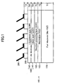
- FIG. 1 illustrates one example of a structure (bonding member) having an air electrode of an SOFC cell and an interconnector bonded to each other by a bonding agent according to the embodiment of the present invention.
- an SOFC cell 100 is a stacked body including a fuel electrode 110, an electrolyte 120 stacked on the fuel electrode 110, a reaction preventing layer 130 stacked on the electrolyte 120, and an air electrode 140 stacked on the reaction preventing layer 130.
- the shape of the cell 100 viewed from the top is, for example, a square having a side of 1 to 30 cm, a rectangle having a long side of 5 to 30 cm and a short side of 3 to 15 cm, or a circle having a diameter of 1 to 30 cm.
- the thickness of the cell 100 is 0.1 to 3 mm.
- the fuel electrode 110 (anode electrode) is, for example, a porous sintered body having a thin plate-like shape composed of nickel oxide NiO and yttria stabilized zirconia YSZ.
- the thickness T of the fuel electrode 110 is 0.1 to 3 mm.
- the thickness of the fuel electrode 110 is the greatest among the respective components of the cell 100, so that the fuel electrode 110 serves as a support substrate of the cell 100.
- the electrolyte 120 is a dense sintered body having a thin plate-like shape composed of YSZ.
- the thickness T2 of the electrolyte 120 is 3 to 30 ⁇ m.
- the reaction preventing layer 130 is a dense sintered body having a thin plate-like shape composed of celia. Specific examples of celia include GDC (gadolinium-doped celia), SDC (samarium-doped celia), etc.
- the thickness T3 of the reaction preventing layer 130 is 3 to 20 ⁇ m.
- the reaction preventing layer 130 is interposed between the electrolyte 120 and the air electrode layer 140 in order to prevent the occurrence of the phenomenon in which an electric resistance between the electrolyte 120 and the air electrode 140 increases through the reaction between the YSZ in the electrolyte 120 and the strontium in the air electrode 140 during the fabrication of the cell or in the cell 100, which is currently operated, of the SOFC.
- the air electrode 140 (cathode electrode) includes two layers, which are a base layer 141 and an outermost layer 142.
- the base layer 141 is a porous sintered body having a thin plate-like shape and made of lanthanum strontium cobalt ferrite LSCF (La 0.6 Sr 0.4 Co 0.2 Fe 0.8 O 3 ).
- the outermost layer 142 is a porous sintered body having a thin plate-like shape and having a perovskite structure containing manganese.
- the outermost layer 142 is made of, for example, lanthanum strontium manganite LSM (La 0.6 Sr 0.2 MnO 3 ), lanthanum manganite LM (LaMnO 3 ), etc.
- the thickness T1 of the base layer 141 is 5 to 50 ⁇ m
- the thickness T2 of the outermost layer 142 is 5 to 50 ⁇ m.
- the air electrode 140 has two-layer structure is based upon the fact that the reaction speed of the LSCF of the chemical reaction represented by the formula (1) is higher than that of the LSM because the activity of the LSCF is higher than that of the LSM, and upon the fact that the bonding strength of the LSM to the bonding agent containing the spinel type material is greater than that of the LSCF.
- the air electrode layer 140 includes two layers in order to increase the reaction speed for the chemical reaction represented by the formula (1) in the air electrode 140 and to increase the bonding strength between the air electrode and the bonding agent.
- the base layer 141 includes only one layer that is the LSCF layer.
- the base layer 141 may include plural layers.
- the base layer 141 may include two layers, which are the LSCF layer (air electrode) stacked on the reaction preventing layer 130 and a lanthanum strontium cobalt LSC (La 0,8 Sr 0,2 CoO 3 ) layer (current-collecting layer) stacked on the LSCF layer (i.e., interposed between the LSCF layer and the outermost layer (LSM layer) 142).
- an LSCF layer thermal stress buffer layer
- the base layer 141 may include three layers).
- LSC lanthanum strontium ferrite LSF
- LaNi 0.6 Fe 0.4 O 3 lanthanum nickel ferrite LNF
- the interconnector 200 is a conductive connection member made of a ferrite SUS material.
- the bonding portion of each of the plural interconnectors 200, each having the same shape, and the bonding portion of the outermost layer (i.e., LSM layer) of the air electrode 140 in the cell 100 is bonded and electrically connected by the bonding agent 300.
- the bonding agent 300 is a sintered body made of a transition metal oxide having a spinel type crystal structure.
- the bonding agent 300 is made of MnCo 2 O 4 , CuMn 2 O 4 , etc.
- the thickness TA of the layer of the bonding agent 300 is 20 to 500 ⁇ m.
- a noble metal such as Pt or Ag may be contained in the bonding agent 300. The electric resistance of the bonding agent can be reduced by containing the noble metal into the bonding agent 300.
- the fuel electrode layer 110 is formed as described below. Specifically, 60 parts by weight of NiO powder, and 40 parts by weight of YSZ powder are mixed, and polyvinyl alcohol (PVA) is added to the mixture as a binder, whereby slurry is prepared. This slurry is dried and granulated with a spray dryer to obtain powders for the fuel electrode. The powders are molded with a die press molding, and then, the resultant is sintered in an electric furnace at 1400 °C for 3 hours in air, whereby the fuel electrode 110 is fabricated.
- PVA polyvinyl alcohol
- the electrolyte 120 is formed on the fuel electrode 110 as described below. Specifically, water and binder are added into YSZ powder, and the resultant mixture is mixed with a ball mill for 24 hours to prepare slurry.
- This slurry is applied on the fuel electrode 110, dried, and then, co-sintered in an electric furnace at 1400 °C for 2 hours in air, whereby the electrolyte 120 is formed on the fuel electrode 110.
- a tape staking method, printing method, etc. may be used.
- the reaction preventing layer 130 is formed on the electrolyte 120 as described below. Specifically, water and binder are added into GDC powder, and the resultant mixture is mixed with a ball mill for 24 hours to prepare slurry. The slurry is applied on the electrolyte 120, dried, and then, sintered in an electric furnace at 1350 °C for 1 hour in air, whereby the reaction preventing layer 130 is formed on the electrolyte 120. When a film, which is to become the reaction preventing layer 130 afterward, is formed on the electrolyte 120, a tape staking method, printing method, etc. may be used. The reaction preventing layer 130 may be formed with co-sintering.
- the base layer 141 of the air electrode 140 is formed on the reaction preventing layer 130 as described below. Specifically, water and binder are added into LSCF powder, and the resultant mixture is mixed with a ball mill for 24 hours to prepare slurry. The slurry is applied on the reaction preventing layer 130, dried, and then, sintered in an electric furnace at 1000 °C for 1 hour in air, whereby the air electrode 140 is formed on the reaction preventing layer 130.
- the outermost layer 142 is formed on the base layer 141 as described below. Specifically, water and binder are added into LSM powder, and the resultant mixture is mixed with a ball mill for 24 hours to prepare slurry. The slurry is applied on the base layer 141, dried, and then, sintered in an electric furnace at 1000 °C for 1 hour in air, whereby the outermost layer 142 is formed on the base layer 141.
- One example of the method of fabricating the cell 100 has been described above.
- the interconnector 200 is formed by processing a ferrite SUS material into a predetermined shape by a machining process. Plural interconnectors 200, each having the same shape, are prepared.
- the outermost layer 142 and the interconnector 200 are bonded by the bonding agent 300 as described below.
- the case in which the spinel type material is MnCo 2 O 4 will be described as one example.
- metal powder of manganese Mn and metal powder of cobalt Co are weighed and mixed with a molar ratio of 1:2.
- the diameter of the metal powder is 0.5 to 5 ⁇ m, and the average diameter is 2 ⁇ m.
- a noble metal powder such as Pt or Ag may be added thereto.
- Ethyl cellulose serving as binder and terpineol serving as a solvent are added to the mixture, according to need, and the resultant mixture is mixed in a mortar to form a paste used for bonding.
- the bonding paste is applied onto the bonding portion between the surface of the outermost layer 142 (i.e., LSM layer) of the air electrode 140 in the cell 100 and the interconnector 200, whereby the outermost layer 142 and the interconnector 200 are bonded to each other. Thereafter, this paste is dried at 100°C for 1 hour, and then, sintered in air for 1 hour at a relatively low temperature of 850 °C, whereby the bonding agent 300, which is a sintered body, is formed.
- LSM layer outermost layer
- the powders of the respective metal elements constituting the spinel type material are used as a starting material, and the powders are oxidized upon the sintering, whereby the bonding agent 300 having the spinel type material is formed.
- the outermost layer 142 and the interconnector 200 are bonded and electrically connected with this bonding agent 300.
- One example of the method of fabricating the bonding member of the air electrode in the SOFC cell illustrated in FIG. 1 and the interconnector has been described above.
- Japanese Unexamined Patent Application No. 2009-16351 discloses that an air electrode made of manganese spinel compound is bonded to a metal interconnector with a bonding agent made of a manganese spinel compound (see especially paragraph 0029).
- a manganese compound is produced in such a manner that powders of manganese oxide and powders of cobalt oxide are mixed with a spinel ratio, and the resultant mixture is sintered.
- the fabrication method of the bonding agent 300 according to the present embodiment is totally different from the fabrication method of a normal manganese spinel compound.
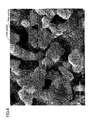
- FIG. 2 is a view (SEM image) illustrating the surface of the bonding agent 300 that is observed at a magnification of 1000
- FIGS. 3 and 5 are views illustrating the surface of the bonding agent 300 that is observed at a magnification of 5000
- FIGS. 4 and 6 are views illustrating the surface of the bonding agent 300 that is observed at a magnification of 10000.
- the bonding agent 300 has a "co-continuous structure".
- a thickness of an "arm portion” that three-dimensionally (stereoscopically) links many “base portions” (the portions from which two or more arm portions extend) is 0.3 to 2.5 ⁇ m.
- the “thickness of the arm portion” is calculated as described below in the present embodiment. Specifically, 10 portions having the co-continuous structure are firstly extracted from the SEM image. Three data pieces each for the respective portions involved with the thickness of the arm portion measured from the extracted portions are collected. The “thickness of the arm portion” is calculated based upon the obtained 30 data pieces in total. It is considered that the formation of the "co-continuous structure" is related to the above-mentioned "growth action of the spinel type crystal due to the heat generated by the oxidation reaction during when the paste is sintered".
- the bonding agent 300 includes spherical plural particles, each of which has plural crystal faces exposed to the surface. These particles are dispersed in the "co-continuous structure".
- the diameter of each of the plural particles is 5 to 80 ⁇ m.
- the diameter of the particle the longest one of the linear distances (the length corresponding to the diameter) passing through the center of the spherical particle in the particle is adopted.
- the plural particles include at least one or more particles having a side of 1 ⁇ m or more of plural sides constituting the outline of the crystal surface (see FIG. 6 ).
- the formation of the "particle” is considered to be related to the above-mentioned "growth action of the spinel type crystal due to the heat generated by the oxidation reaction during when the paste is sintered".
- the bonding agent having the above-mentioned feature is synthesized by using a metal as a starting material, and by utilizing a reaction heat during the heat treatment.
- a metal as a starting material
- an organic metal may be used as the starting material.
- di-i-propoxymanganese(II) (chemical formula: Mn(O-i-C 3 H 7 ) 2 ) as an organic metal containing manganese
- di-i-propoxycobalt(II) (chemical formula: Co(O-i-C 3 H 7 ) 2 ) as an organic metal containing cobalt
- bis(dibivalloyl metanate) copper (chemical formula: Cu(C 11 H 18 O 2 ) 2 ) as an organic metal containing copper, can be used.
- a bonding agent that is formed by using a powder of spinel type material, which is synthesized beforehand, as a starting material is prepared as a comparative example.
- the bonding agent according to the comparative example is formed as described below.
- the spinel type material (MnCo 2 O 4 ) synthesized according to a predetermined process is pulverized by a pot mill, whereby powders of the spinel type material (complex oxide) are obtained.
- the diameter of the powder is 0.2 to 2 ⁇ m, and the average diameter is 0.5 ⁇ m.
- Ethyl cellulose serving as binder and terpineol serving as a solvent are added to this powder, according to need, to prepare a bonding paste.
- the outermost layer 142 and the interconnector 200 are bonded by using this paste, and this paste is dried for 1 hour at 100 °C. Thereafter, the paste is sintered in air for 1 hour at a high temperature of 1000 °C, whereby the bonding agent, which is a sintered body, according to the comparative example is formed.
- the paste is not sufficiently densified. This is based upon the fact that, because the oxide paste, which has already been oxidized, is used in the comparative example, the growth action of the spinel type crystal by the heat caused by the oxidation reaction during when the paste is sintered cannot be expected, different from the above-mentioned embodiment.
- FIGS. 7 and 8 are views illustrating the surface of the bonding agent according to the comparative example that is observed at a magnification of 5000 and 10000 with an electron scanning microscope (SEM).
- SEM electron scanning microscope
- the bonding member according to the present embodiment has a bonding strength, between the outermost layer 142 and the bonding agent, greater than that of the bonding member according to the comparative example.
- a test A for confirming this finding will be described below.
- test A plural samples, each of which had a different combination of the material of the bonding agent, the average diameter of the powder that is the starting material of the bonding agent, and the sintering temperature (heat-treatment temperature) during the formation of the bonding agent, were prepared for the respective bonding member according to the present embodiment and the bonding member according to the comparative example. Specifically, 18 types of standards
- the shape of the interconnector 200 and the shape of the bonding agent as viewed from the top in these samples are the same plate-like shape.
- the air electrode 140 specifically, the outermost layer 142
- the interconnector 200 which have the same shape as viewed from the top, are bonded by the bonding agent all over the bonding surface.
- the thickness T1 of the fuel electrode 110 is 500 ⁇ m
- the thickness T2 of the electrolyte 120 (3YSZ) is 5 ⁇ m
- the thickness T3 of the reaction preventing layer 130 (GDC) is 5 ⁇ m
- the thickness T41 of the base layer 141 (LSCF) of the air electrode 140 is 30 ⁇ m
- the thickness T42 of the outermost layer 142 (LSM) is 20 ⁇ m
- the thickness TA of the bonding agent 300 is 200 ⁇ m
- the thickness TB of the interconnector 200 is 450 ⁇ m, those of which are constant.
- the shape of each of the samples viewed from the top is a circle having a diameter of 30 cm.
- thermosetting epoxy bonding agent (trade name: TB2222P) by Three Bond Co., Ltd., having a great bonding force, was used as the epoxy resin.
- the epoxy resin having the great bonding force was used in order to obtain a bonding strength greater than the bonding strength at the bonding portion by the bonding agent 300.
- the condition (bonding condition) for curing the epoxy resin was 100°C for 60 minutes.
- tensile strength The magnitude of the tensile force (hereinafter referred to as "tensile strength") when the bonding portion by the bonding agent was destroyed was measured.
- the bonded portion (the weakest portion) destroyed in the samples according to the present embodiment was the bonded portion (interface) between the outermost layer 142 and the bonding agent, while the bonded portion destroyed in the samples according to the comparative example (standards 9 to 11, 16 to 18) is the inside of the bonding agent. Table 2 shows the result.
- Table 2 Standard Tensile strength (MPa) Destroyed portion 1 49 Interface of bonding agent/outermost layer 2 50 Interface of bonding agent/outermost layer 3 45 Interface of bonding agent/outermost layer 4 42 Interface of bonding agent/outermost layer 5 55 Interface of bonding agent/outermost layer 6 51 Interface of bonding agent/outermost layer 7 48 Interface of bonding agent/outermost layer 8 47 Interface of bonding agent/outermost layer 9 13 Inside of bonding agent 10 16 Inside of bonding agent 11 17 Inside of bonding agent 12 48 Interface of bonding agent/outermost layer 13 46 Interface of bonding agent/outermost layer 14 53 Interface of bonding agent/outermost layer 15 51 Interface of bonding agent/outermost layer 16 16 Inside of bonding agent 17 18 Inside of bonding agent 18 20 Inside of bonding agent (MPa) Destroyed portion 1 49 Interface of bonding agent/outermost layer 2 50 Interface of bonding agent/outermost layer 3 45 Interface of bonding agent/outermost layer 4 42 Interface of bonding agent/out
- the bonding agent 300 according to the present embodiment tends to have the tensile strength greater than that of the bonding agent according to the comparative example. Specifically, it can be said that the bonding agent 300 according to the present embodiment has a bonding strength between the outermost layer 142 and the bonding agent greater than the bonding strength of the bonding agent according to the comparative example.
- the present inventor has found that the bonding member according to the present embodiment has an electric resistance greater than that of the bonding member according to the comparative example (has conductivity higher than that of the bonding member according to the comparative example).
- a test B for confirming this finding will be described below.
- Test B plural samples, each of which has the combination similar to the Test A and corresponds to FIG. 1 , were prepared for the respective bonding member according to the present embodiment and the bonding member according to the comparative example.
- 18 types of standards (combinations) illustrated in Table 1 were prepared. 3 samples were produced for each standard.
- those (standards 1 to 8, 12 to 15) in which the starting material is the powders (metal powders) of the respective metal elements constituting the spinel type material correspond to the present embodiment, while those (standards 9 to 11, 16 to 18) in which the starting material is the powder (ceramic powder) of the spinel type material that is synthesized beforehand correspond to the comparative example.
- the shape and size except for the interconnector and the bonding agent were the same as those in the samples in Test A.
- an interconnector (made of Ni) at the fuel electrode side was bonded to the surface of the fuel electrode 110 in each sample.
- the interconnector was bonded by sintering a bonding paste made of Ni.
- the temperature of each sample was raised up to 800 °C, while supplying nitrogen gas to the fuel electrode 110 and supplying air to the air electrode 140.
- a reduction process was performed for 3 hours, while supplying hydrogen gas to the air electrode 110.
- an output (output density) taken out to the outside through the interconnector 200 at the side of the air electrode 140 and the interconnector at the side of the fuel electrode 110 was measured.
- the value at the temperature of 800°C and rated voltage of 0.8 V was used as the output density.
- the greater output density means the reduced electric resistance. Table 3 illustrates the result.
- the bonding member according to the present embodiment tends to have the output density greater than that of the bonding member according to the comparative example. Specifically, it can be said that the bonding agent 300 according to the present embodiment has an electric resistance smaller than that of the bonding agent according to the comparative example.
- the bonding agent according to the present embodiment which is formed by using powders of the respective metal elements (Mn, Co) constituting the spinel type material as a starting material, has greater conductivity (smaller electric resistance) and greater bonding strength compared to the bonding agent according to the comparative example, which is formed by using powders of spinel type material (MnCo 2 O 4 ) synthesized beforehand as the starting material.
- the paste is sufficiently densified even if the sintering temperature is set to be relatively low (e.g., 700 to 900 °C), whereby the bonding agent having sufficiently small electric resistance, and sufficiently great bonding strength can be obtained.
- the bonding agent is formed by using the powders of the respective metal elements (Mn, Co) constituting the spinel type material as a starting material in case where the air electrode 140 (corresponding to the above-mentioned "first conductive connection member") and the interconnector 200 (corresponding to the above-mentioned “second conductive connection member") are bonded by the bonding agent containing "the transition metal oxide (MnCo 2 O 4 , CuMn 2 O 4 , etc.) having the spinel type crystal structure", the bonding agent has greater conductivity (smaller electric resistance) and greater bonding strength compared to the bonding agent according to the comparative example, which is formed by using powders of spinel type material (MnCo 2 O 4 ) synthesized beforehand as the starting material.
- the bonding agent has greater conductivity (smaller electric resistance) and greater bonding strength compared to the bonding agent according to the comparative example, which is formed by using powders of spinel type material (MnCo 2 O 4 ) synthesized beforehand as the starting material.
- the bonding agent containing "the transition metal oxide (MnCo 2 O 4 , CuMn 2 O 4 , etc.) having the spinel type crystal structure" the bonding agent has greater conductivity (smaller electric resistance) and greater bonding strength, compared to the bonding agent according to the comparative example, which is formed by using powders of spinel type material (MnCo 2 O 4 ) synthesized beforehand as the starting material, if the bonding agent is formed by using the powders of the respective metal elements (Mn, Co) constituting the spinel type material as a starting material.
- the chemical formula of lanthanum chromite LC is expressed by the following formula (3).
- A is at least one type of element selected from Ca, Sr, and Ba.
- B is at least one type of element selected from Co, Ni, V, Mg, and Al.
- the range of x is 0 to 0.4, and more preferably 0.05 to 0.2.
- the range of y is 0 to 0.3, and more preferably 0.02 to 0.22.
- the range of z is 0 to 0.1, and more preferably 0.02 to 0.05.
- ⁇ is a minute value containing 0. La 1-x A x Cr 1-y+z B y O 3- ⁇ (3)
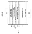
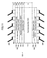
- the conductive portion 150 has two layers that are a base layer 151 made of LC and an outermost layer 152 made of LSM.
- the reason why the outermost (LSM layer) is formed is based upon the fact that the bonding strength between the conductive portion 150 and the bonding agent 300 increases more than the case in which the outermost (LSM layer) is not formed.
- a base layer 151 made of titanium oxide may be used instead of the base layer 151 made of LC in the conductive portion 150.
- the chemical formula of the titanium oxide is represented by the following formula (4).
- A is at least one type of element selected from alkaline-earth elements.
- B is at least one type of element selected from Sc, Y, and lanthanoid element.
- D is at least one type of element selected from fourth-period, fifth-period, and sixth-period transition metals, Al, Si, Zn, Ga, Ge, Sn, Sb, Pb, and Bi.
- the range of x is 0 to 0.5
- the range of y is 0 to 0.5
- the range of z is -0.05 to 0.05.
- ⁇ is a minute value containing 0. "Strontium titanate SrTiO 3 " using strontium Sr can be employed as A, for example.
- the bonding agent when the bonding agent is formed by using the powders of the respective metal elements (Mn, Co) constituting the spinel type material as a starting material in case where the first conductive connection member and the second conductive connection member are bonded by the bonding agent containing "the transition metal oxide (MnCo 2 O 4 , CuMn 2 O 4 , etc.) having the spinel type crystal structure", the bonding agent has greater conductivity (smaller electric resistance) and greater bonding strength compared to the bonding agent, which is formed by using powders of spinel type material (MnCo 2 O 4 ) synthesized beforehand as the starting material.
Landscapes
- Chemical & Material Sciences (AREA)
- Chemical Kinetics & Catalysis (AREA)
- Manufacturing & Machinery (AREA)
- Sustainable Development (AREA)
- Sustainable Energy (AREA)
- Engineering & Computer Science (AREA)
- Life Sciences & Earth Sciences (AREA)
- Electrochemistry (AREA)
- General Chemical & Material Sciences (AREA)
- Inorganic Chemistry (AREA)
- Fuel Cell (AREA)
- Ceramic Products (AREA)
- Adhesives Or Adhesive Processes (AREA)
- Conductive Materials (AREA)
Applications Claiming Priority (3)
| Application Number | Priority Date | Filing Date | Title |
|---|---|---|---|
| JP2009195071 | 2009-08-26 | ||
| JP2009242621 | 2009-10-21 | ||
| JP2010110707A JP4901976B2 (ja) | 2009-08-26 | 2010-05-13 | 接合剤 |
Publications (2)
| Publication Number | Publication Date |
|---|---|
| EP2302719A1 true EP2302719A1 (fr) | 2011-03-30 |
| EP2302719B1 EP2302719B1 (fr) | 2016-10-26 |
Family
ID=43063784
Family Applications (1)
| Application Number | Title | Priority Date | Filing Date |
|---|---|---|---|
| EP10251326.4A Not-in-force EP2302719B1 (fr) | 2009-08-26 | 2010-07-26 | Agent de liaison |
Country Status (3)
| Country | Link |
|---|---|
| US (1) | US8486328B2 (fr) |
| EP (1) | EP2302719B1 (fr) |
| JP (1) | JP4901976B2 (fr) |
Cited By (1)
| Publication number | Priority date | Publication date | Assignee | Title |
|---|---|---|---|---|
| CN103715099A (zh) * | 2012-10-05 | 2014-04-09 | 旭德科技股份有限公司 | 接合导热基板与金属层的方法 |
Families Citing this family (6)
| Publication number | Priority date | Publication date | Assignee | Title |
|---|---|---|---|---|
| JP6396889B2 (ja) * | 2013-03-19 | 2018-09-26 | 日本碍子株式会社 | 接合体及びその製造方法 |
| JP6465546B2 (ja) * | 2013-12-24 | 2019-02-06 | 日本特殊陶業株式会社 | 固体酸化物形燃料電池及びその製造方法 |
| JP6358921B2 (ja) * | 2014-04-01 | 2018-07-18 | 大阪瓦斯株式会社 | 固体酸化物形燃料電池用セルの製造方法、及び、セル間接続部材接合方法 |
| JP6275561B2 (ja) * | 2014-06-17 | 2018-02-07 | 日本特殊陶業株式会社 | 接合体、接合体の製造方法、固体酸化物形燃料電池、及び水電解装置 |
| WO2016152923A1 (fr) * | 2015-03-26 | 2016-09-29 | 日本特殊陶業株式会社 | Unité de réaction électrochimique et empilement de piles à combustible |
| JP6599287B2 (ja) * | 2016-06-22 | 2019-10-30 | 株式会社ノリタケカンパニーリミテド | 導電層転写シート |
Citations (4)
| Publication number | Priority date | Publication date | Assignee | Title |
|---|---|---|---|---|
| JP2005339904A (ja) | 2004-05-25 | 2005-12-08 | Kyocera Corp | 燃料電池セルスタック及び燃料電池 |
| JP2009016351A (ja) | 2007-07-05 | 2009-01-22 | General Electric Co <Ge> | 改良電極を有する固体酸化物型電気化学デバイス |
| EP2224516A1 (fr) * | 2009-02-04 | 2010-09-01 | NGK Insulators, Ltd. | Dispositif électrochimique |
| EP2223897A1 (fr) * | 2009-02-04 | 2010-09-01 | NGK Insulators, Ltd. | Procédé de fabrication d'un oxyde de métal de transition doté d'une structure de spinelle |
Family Cites Families (8)
| Publication number | Priority date | Publication date | Assignee | Title |
|---|---|---|---|---|
| JP2000053424A (ja) * | 1998-07-24 | 2000-02-22 | Sulzer Hexis Ag | インタ―コネクタのコ―ティングのためのペロブスカイト、インタ―コネクタ及び燃料セル電池 |
| WO2001028024A1 (fr) * | 1999-10-08 | 2001-04-19 | Global Thermoelectric Inc. | Electrodes composites pour composants electrochimiques a semi-conducteur |
| AT4810U1 (de) * | 2001-05-31 | 2001-11-26 | Plansee Ag | Stromsammler für sofc-brennstoffzellen |
| US7645535B2 (en) * | 2005-11-14 | 2010-01-12 | General Electric Company | Method and materials for bonding electrodes to interconnect layers in solid oxide fuel cell stacks |
| JP5283896B2 (ja) * | 2007-12-19 | 2013-09-04 | 東京瓦斯株式会社 | 固体酸化物形燃料電池用インターコネクタへの保護膜コーティング方法 |
| JP5483714B2 (ja) * | 2009-08-26 | 2014-05-07 | 日本碍子株式会社 | 接合剤 |
| JP5346873B2 (ja) * | 2009-08-26 | 2013-11-20 | 日本碍子株式会社 | 接合剤 |
| JP4866955B2 (ja) * | 2009-11-09 | 2012-02-01 | 日本碍子株式会社 | 接合体 |
-
2010
- 2010-05-13 JP JP2010110707A patent/JP4901976B2/ja active Active
- 2010-07-16 US US12/837,708 patent/US8486328B2/en active Active
- 2010-07-26 EP EP10251326.4A patent/EP2302719B1/fr not_active Not-in-force
Patent Citations (4)
| Publication number | Priority date | Publication date | Assignee | Title |
|---|---|---|---|---|
| JP2005339904A (ja) | 2004-05-25 | 2005-12-08 | Kyocera Corp | 燃料電池セルスタック及び燃料電池 |
| JP2009016351A (ja) | 2007-07-05 | 2009-01-22 | General Electric Co <Ge> | 改良電極を有する固体酸化物型電気化学デバイス |
| EP2224516A1 (fr) * | 2009-02-04 | 2010-09-01 | NGK Insulators, Ltd. | Dispositif électrochimique |
| EP2223897A1 (fr) * | 2009-02-04 | 2010-09-01 | NGK Insulators, Ltd. | Procédé de fabrication d'un oxyde de métal de transition doté d'une structure de spinelle |
Cited By (1)
| Publication number | Priority date | Publication date | Assignee | Title |
|---|---|---|---|---|
| CN103715099A (zh) * | 2012-10-05 | 2014-04-09 | 旭德科技股份有限公司 | 接合导热基板与金属层的方法 |
Also Published As
| Publication number | Publication date |
|---|---|
| JP2011108621A (ja) | 2011-06-02 |
| JP4901976B2 (ja) | 2012-03-21 |
| US8486328B2 (en) | 2013-07-16 |
| US20110052916A1 (en) | 2011-03-03 |
| EP2302719B1 (fr) | 2016-10-26 |
Similar Documents
| Publication | Publication Date | Title |
|---|---|---|
| JP5483714B2 (ja) | 接合剤 | |
| US8617769B2 (en) | Coating body | |
| JP5075183B2 (ja) | 電気化学装置 | |
| US8419866B2 (en) | Method of manufacturing transition metal oxide having spinel structure | |
| EP2302719B1 (fr) | Agent de liaison | |
| EP2320507B1 (fr) | Élément de liaison | |
| US8574784B2 (en) | Solid oxide fuel cell including electrode containing dense bonding portions and porous non-bonding portions | |
| JP5346873B2 (ja) | 接合剤 | |
| JP5470326B2 (ja) | 成形体 | |
| US10511033B2 (en) | Solid oxide fuel cell | |
| JPWO2011138915A1 (ja) | 高温構造材料、固体電解質形燃料電池用構造体および固体電解質形燃料電池 | |
| JP5422414B2 (ja) | 固体酸化物形燃料電池のセル | |
| JP5079991B2 (ja) | 燃料電池セル及び燃料電池 | |
| JP6836156B2 (ja) | 燃料電池 | |
| JP4913257B1 (ja) | 固体酸化物形燃料電池 | |
| JP2004165074A (ja) | 固体酸化物形燃料電池用集電体材料 |
Legal Events
| Date | Code | Title | Description |
|---|---|---|---|
| PUAI | Public reference made under article 153(3) epc to a published international application that has entered the european phase |
Free format text: ORIGINAL CODE: 0009012 |
|
| AK | Designated contracting states |
Kind code of ref document: A1 Designated state(s): AL AT BE BG CH CY CZ DE DK EE ES FI FR GB GR HR HU IE IS IT LI LT LU LV MC MK MT NL NO PL PT RO SE SI SK SM TR |
|
| AX | Request for extension of the european patent |
Extension state: BA ME RS |
|
| 17P | Request for examination filed |
Effective date: 20110812 |
|
| REG | Reference to a national code |
Ref country code: DE Ref legal event code: R079 Ref document number: 602010037434 Country of ref document: DE Free format text: PREVIOUS MAIN CLASS: H01M0002200000 Ipc: H01M0008028200 |
|
| GRAP | Despatch of communication of intention to grant a patent |
Free format text: ORIGINAL CODE: EPIDOSNIGR1 |
|
| RIC1 | Information provided on ipc code assigned before grant |
Ipc: H01M 4/90 20060101ALN20160523BHEP Ipc: H01M 8/0297 20160101ALI20160523BHEP Ipc: H01M 8/124 20160101ALN20160523BHEP Ipc: H01M 8/0282 20160101AFI20160523BHEP |
|
| INTG | Intention to grant announced |
Effective date: 20160608 |
|
| RIN1 | Information on inventor provided before grant (corrected) |
Inventor name: RYU, TAKASHI Inventor name: NAKAMURA, TOSHIYUKI Inventor name: OHMORI, MAKOTO |
|
| GRAS | Grant fee paid |
Free format text: ORIGINAL CODE: EPIDOSNIGR3 |
|
| GRAA | (expected) grant |
Free format text: ORIGINAL CODE: 0009210 |
|
| AK | Designated contracting states |
Kind code of ref document: B1 Designated state(s): AL AT BE BG CH CY CZ DE DK EE ES FI FR GB GR HR HU IE IS IT LI LT LU LV MC MK MT NL NO PL PT RO SE SI SK SM TR |
|
| REG | Reference to a national code |
Ref country code: GB Ref legal event code: FG4D |
|
| REG | Reference to a national code |
Ref country code: CH Ref legal event code: EP |
|
| REG | Reference to a national code |
Ref country code: AT Ref legal event code: REF Ref document number: 840594 Country of ref document: AT Kind code of ref document: T Effective date: 20161115 |
|
| REG | Reference to a national code |
Ref country code: IE Ref legal event code: FG4D |
|
| REG | Reference to a national code |
Ref country code: DE Ref legal event code: R096 Ref document number: 602010037434 Country of ref document: DE |
|
| REG | Reference to a national code |
Ref country code: LT Ref legal event code: MG4D |
|
| PG25 | Lapsed in a contracting state [announced via postgrant information from national office to epo] |
Ref country code: LV Free format text: LAPSE BECAUSE OF FAILURE TO SUBMIT A TRANSLATION OF THE DESCRIPTION OR TO PAY THE FEE WITHIN THE PRESCRIBED TIME-LIMIT Effective date: 20161026 |
|
| REG | Reference to a national code |
Ref country code: NL Ref legal event code: MP Effective date: 20161026 |
|
| REG | Reference to a national code |
Ref country code: AT Ref legal event code: MK05 Ref document number: 840594 Country of ref document: AT Kind code of ref document: T Effective date: 20161026 |
|
| PG25 | Lapsed in a contracting state [announced via postgrant information from national office to epo] |
Ref country code: NO Free format text: LAPSE BECAUSE OF FAILURE TO SUBMIT A TRANSLATION OF THE DESCRIPTION OR TO PAY THE FEE WITHIN THE PRESCRIBED TIME-LIMIT Effective date: 20170126 Ref country code: SE Free format text: LAPSE BECAUSE OF FAILURE TO SUBMIT A TRANSLATION OF THE DESCRIPTION OR TO PAY THE FEE WITHIN THE PRESCRIBED TIME-LIMIT Effective date: 20161026 Ref country code: LT Free format text: LAPSE BECAUSE OF FAILURE TO SUBMIT A TRANSLATION OF THE DESCRIPTION OR TO PAY THE FEE WITHIN THE PRESCRIBED TIME-LIMIT Effective date: 20161026 Ref country code: GR Free format text: LAPSE BECAUSE OF FAILURE TO SUBMIT A TRANSLATION OF THE DESCRIPTION OR TO PAY THE FEE WITHIN THE PRESCRIBED TIME-LIMIT Effective date: 20170127 |
|
| PG25 | Lapsed in a contracting state [announced via postgrant information from national office to epo] |
Ref country code: NL Free format text: LAPSE BECAUSE OF FAILURE TO SUBMIT A TRANSLATION OF THE DESCRIPTION OR TO PAY THE FEE WITHIN THE PRESCRIBED TIME-LIMIT Effective date: 20161026 Ref country code: IS Free format text: LAPSE BECAUSE OF FAILURE TO SUBMIT A TRANSLATION OF THE DESCRIPTION OR TO PAY THE FEE WITHIN THE PRESCRIBED TIME-LIMIT Effective date: 20170226 Ref country code: AT Free format text: LAPSE BECAUSE OF FAILURE TO SUBMIT A TRANSLATION OF THE DESCRIPTION OR TO PAY THE FEE WITHIN THE PRESCRIBED TIME-LIMIT Effective date: 20161026 Ref country code: FI Free format text: LAPSE BECAUSE OF FAILURE TO SUBMIT A TRANSLATION OF THE DESCRIPTION OR TO PAY THE FEE WITHIN THE PRESCRIBED TIME-LIMIT Effective date: 20161026 Ref country code: BE Free format text: LAPSE BECAUSE OF FAILURE TO SUBMIT A TRANSLATION OF THE DESCRIPTION OR TO PAY THE FEE WITHIN THE PRESCRIBED TIME-LIMIT Effective date: 20161026 Ref country code: ES Free format text: LAPSE BECAUSE OF FAILURE TO SUBMIT A TRANSLATION OF THE DESCRIPTION OR TO PAY THE FEE WITHIN THE PRESCRIBED TIME-LIMIT Effective date: 20161026 Ref country code: PL Free format text: LAPSE BECAUSE OF FAILURE TO SUBMIT A TRANSLATION OF THE DESCRIPTION OR TO PAY THE FEE WITHIN THE PRESCRIBED TIME-LIMIT Effective date: 20161026 Ref country code: HR Free format text: LAPSE BECAUSE OF FAILURE TO SUBMIT A TRANSLATION OF THE DESCRIPTION OR TO PAY THE FEE WITHIN THE PRESCRIBED TIME-LIMIT Effective date: 20161026 Ref country code: PT Free format text: LAPSE BECAUSE OF FAILURE TO SUBMIT A TRANSLATION OF THE DESCRIPTION OR TO PAY THE FEE WITHIN THE PRESCRIBED TIME-LIMIT Effective date: 20170227 |
|
| REG | Reference to a national code |
Ref country code: DE Ref legal event code: R097 Ref document number: 602010037434 Country of ref document: DE |
|
| PG25 | Lapsed in a contracting state [announced via postgrant information from national office to epo] |
Ref country code: CZ Free format text: LAPSE BECAUSE OF FAILURE TO SUBMIT A TRANSLATION OF THE DESCRIPTION OR TO PAY THE FEE WITHIN THE PRESCRIBED TIME-LIMIT Effective date: 20161026 Ref country code: SK Free format text: LAPSE BECAUSE OF FAILURE TO SUBMIT A TRANSLATION OF THE DESCRIPTION OR TO PAY THE FEE WITHIN THE PRESCRIBED TIME-LIMIT Effective date: 20161026 Ref country code: RO Free format text: LAPSE BECAUSE OF FAILURE TO SUBMIT A TRANSLATION OF THE DESCRIPTION OR TO PAY THE FEE WITHIN THE PRESCRIBED TIME-LIMIT Effective date: 20161026 Ref country code: DK Free format text: LAPSE BECAUSE OF FAILURE TO SUBMIT A TRANSLATION OF THE DESCRIPTION OR TO PAY THE FEE WITHIN THE PRESCRIBED TIME-LIMIT Effective date: 20161026 Ref country code: EE Free format text: LAPSE BECAUSE OF FAILURE TO SUBMIT A TRANSLATION OF THE DESCRIPTION OR TO PAY THE FEE WITHIN THE PRESCRIBED TIME-LIMIT Effective date: 20161026 |
|
| PG25 | Lapsed in a contracting state [announced via postgrant information from national office to epo] |
Ref country code: BG Free format text: LAPSE BECAUSE OF FAILURE TO SUBMIT A TRANSLATION OF THE DESCRIPTION OR TO PAY THE FEE WITHIN THE PRESCRIBED TIME-LIMIT Effective date: 20170126 Ref country code: IT Free format text: LAPSE BECAUSE OF FAILURE TO SUBMIT A TRANSLATION OF THE DESCRIPTION OR TO PAY THE FEE WITHIN THE PRESCRIBED TIME-LIMIT Effective date: 20161026 Ref country code: SM Free format text: LAPSE BECAUSE OF FAILURE TO SUBMIT A TRANSLATION OF THE DESCRIPTION OR TO PAY THE FEE WITHIN THE PRESCRIBED TIME-LIMIT Effective date: 20161026 |
|
| PLBE | No opposition filed within time limit |
Free format text: ORIGINAL CODE: 0009261 |
|
| STAA | Information on the status of an ep patent application or granted ep patent |
Free format text: STATUS: NO OPPOSITION FILED WITHIN TIME LIMIT |
|
| 26N | No opposition filed |
Effective date: 20170727 |
|
| PG25 | Lapsed in a contracting state [announced via postgrant information from national office to epo] |
Ref country code: SI Free format text: LAPSE BECAUSE OF FAILURE TO SUBMIT A TRANSLATION OF THE DESCRIPTION OR TO PAY THE FEE WITHIN THE PRESCRIBED TIME-LIMIT Effective date: 20161026 |
|
| REG | Reference to a national code |
Ref country code: CH Ref legal event code: PL |
|
| GBPC | Gb: european patent ceased through non-payment of renewal fee |
Effective date: 20170726 |
|
| REG | Reference to a national code |
Ref country code: IE Ref legal event code: MM4A |
|
| REG | Reference to a national code |
Ref country code: FR Ref legal event code: ST Effective date: 20180330 |
|
| PG25 | Lapsed in a contracting state [announced via postgrant information from national office to epo] |
Ref country code: LI Free format text: LAPSE BECAUSE OF NON-PAYMENT OF DUE FEES Effective date: 20170731 Ref country code: GB Free format text: LAPSE BECAUSE OF NON-PAYMENT OF DUE FEES Effective date: 20170726 Ref country code: CH Free format text: LAPSE BECAUSE OF NON-PAYMENT OF DUE FEES Effective date: 20170731 Ref country code: IE Free format text: LAPSE BECAUSE OF NON-PAYMENT OF DUE FEES Effective date: 20170726 |
|
| PG25 | Lapsed in a contracting state [announced via postgrant information from national office to epo] |
Ref country code: FR Free format text: LAPSE BECAUSE OF NON-PAYMENT OF DUE FEES Effective date: 20170731 |
|
| PG25 | Lapsed in a contracting state [announced via postgrant information from national office to epo] |
Ref country code: LU Free format text: LAPSE BECAUSE OF NON-PAYMENT OF DUE FEES Effective date: 20170726 |
|
| PG25 | Lapsed in a contracting state [announced via postgrant information from national office to epo] |
Ref country code: MT Free format text: LAPSE BECAUSE OF NON-PAYMENT OF DUE FEES Effective date: 20170726 |
|
| PG25 | Lapsed in a contracting state [announced via postgrant information from national office to epo] |
Ref country code: MC Free format text: LAPSE BECAUSE OF FAILURE TO SUBMIT A TRANSLATION OF THE DESCRIPTION OR TO PAY THE FEE WITHIN THE PRESCRIBED TIME-LIMIT Effective date: 20161026 Ref country code: HU Free format text: LAPSE BECAUSE OF FAILURE TO SUBMIT A TRANSLATION OF THE DESCRIPTION OR TO PAY THE FEE WITHIN THE PRESCRIBED TIME-LIMIT; INVALID AB INITIO Effective date: 20100726 |
|
| PG25 | Lapsed in a contracting state [announced via postgrant information from national office to epo] |
Ref country code: CY Free format text: LAPSE BECAUSE OF NON-PAYMENT OF DUE FEES Effective date: 20161026 |
|
| PG25 | Lapsed in a contracting state [announced via postgrant information from national office to epo] |
Ref country code: MK Free format text: LAPSE BECAUSE OF FAILURE TO SUBMIT A TRANSLATION OF THE DESCRIPTION OR TO PAY THE FEE WITHIN THE PRESCRIBED TIME-LIMIT Effective date: 20161026 |
|
| PG25 | Lapsed in a contracting state [announced via postgrant information from national office to epo] |
Ref country code: TR Free format text: LAPSE BECAUSE OF FAILURE TO SUBMIT A TRANSLATION OF THE DESCRIPTION OR TO PAY THE FEE WITHIN THE PRESCRIBED TIME-LIMIT Effective date: 20161026 |
|
| PG25 | Lapsed in a contracting state [announced via postgrant information from national office to epo] |
Ref country code: AL Free format text: LAPSE BECAUSE OF FAILURE TO SUBMIT A TRANSLATION OF THE DESCRIPTION OR TO PAY THE FEE WITHIN THE PRESCRIBED TIME-LIMIT Effective date: 20161026 |
|
| PGFP | Annual fee paid to national office [announced via postgrant information from national office to epo] |
Ref country code: DE Payment date: 20240529 Year of fee payment: 15 |
|
| REG | Reference to a national code |
Ref country code: DE Ref legal event code: R119 Ref document number: 602010037434 Country of ref document: DE |
|
| PG25 | Lapsed in a contracting state [announced via postgrant information from national office to epo] |
Ref country code: DE Free format text: LAPSE BECAUSE OF NON-PAYMENT OF DUE FEES Effective date: 20260203 |